Abstract
The article discusses results of the analyses of various bearing systems for the rotor of an ORC (Organic Rankine Cycle) microturbine with an electric power of 30 kW. It is impossible to choose the appropriate bearing system taking into account only basic parameters of the bearings. When designing a new power turbine, it is important to conduct the dynamic and strength analysis of the entire rotor-bearings-supporting structure system. The nominal rotational speed of the newly designed single-stage axial-flow turbine is 40,000 rpm. The turbine will be powered using the vapour of a low-boiling working medium. The chosen working medium cannot be used in combination with all materials that are commonly used for turbine constructions. An additional requirement was that the turbogenerator must be oil-free. The temperature of the working medium directed to the rotor blades could exceed a value of 200 °C. Three bearing systems were considered: bearings lubricated with a low-boiling fluid (in the liquid form), gas bearings lubricated with the vapour of a low-boiling medium and rolling bearings. Since the rotors used in those three systems have different geometries, their dynamic properties vary as well. The rotor dynamics analyses were carried out using computer programs belonging to the MESWIR environment, which had been developed at the Institute of Fluid-Flow Machinery of the Polish Academy of Sciences (IMP PAN) in Gdańsk. The computational model, based on the finite element method, was used to prepare graphs on which are presented vibration amplitudes as functions of the rotational speed. The computational model, based on the finite element method, served to perform calculations on the basis of which graphs presenting vibration amplitudes as functions of the rotational speed were prepared. Moreover, vibration trajectories of individual nodes of the computational model were shown. Besides analyses of the bearings themselves, calculations were also carried out to assess the dynamic properties of the rotors supported by those bearings in a wide range of rotational speeds. As a result of the conducted analyses, the concept of an innovative turbogenerator was created. Its rotor can operate at a very high rotational speed, and the bearings do not require oil lubrication.
Highlights
- Characteristics of the newly designed ORC turbine with an electric power of 30 kW were presented.
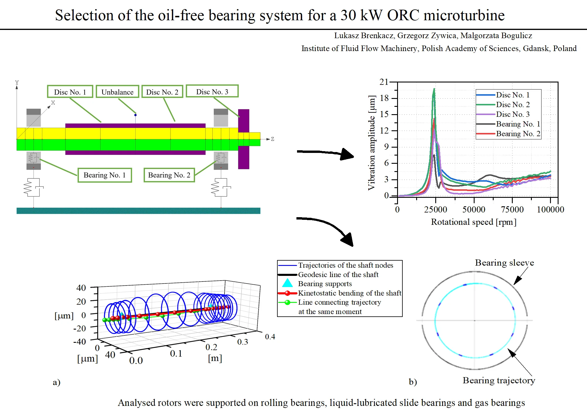
- Numerical analyses of the shaft trajectories of the microturbine’s rotor supported on rolling bearings, liquid-lubricated slide bearings and gas bearings were performed.
- Charts presenting the vibration amplitude vs rotational speed for the microturbine’s rotor supported by bearings of three different types were shown.
- An analysis of the gas bearings’ capacity (in other words, the minimum rotational speeds at which the lubricating film forms itself) depending on the bearing length was shown.
1. Introduction
Micro-cogeneration ORC systems have become increasingly popular in recent years. The growing number of implementations and associated scientific publications is evidence of this. A microturbine is a key subassembly in such systems and has the role of an expansion device. The choice of an appropriate bearing system of the microturbine rotor requires analysing dynamic properties of the entire system. Even though similar tools as those for classical power turbines are available for studying microturbines, other technical problems may generally be encountered. The presence of an unusual lubricating medium often makes it impossible to use commonly used constructional materials. In a system with a low-boiling medium, it is not always possible to employ classical oil-lubricated bearings. A small-sized turbine has to have a high nominal rotational speed in order to achieve a relatively high output power. Taking into consideration all above-mentioned features, it is clear that the systems in question need to be analysed thoroughly at an early stage in their design. Scientific publications, which discuss the dynamics of power microturbines in a wide range of rotational speeds, are currently only a few. Even fewer publications present a comparison of the dynamic properties of the system with different types of bearings. This article bridges this gap by presenting complete results of the numerical analysis, which could be directly compared with results from experimental research that was (or will be) conducted on other turbines of the same type.
All newly designed ORC systems differ widely from one to another, due to the fact that they are used for the production of electricity from waste heat of various thermal parameters. Depending on the place in which such a system is located, its operating parameters (e.g. heat flux or cooling capacity) are different. Different operating parameters make it necessary to use ORC systems that are optimally adapted to technical conditions. It may be necessary, for example, to use various low-boiling fluids, heat exchangers of various construction and size and a suitably adapted expansion device, which is a key component of each ORC system. The expansion device enables the conversion of the low-boiling working medium’s vapour to the rotary motion of the shaft [1]. Scroll expanders [2] and ORC microturbines [3, 4] are among the most commonly used commercial expansion devices. ORC microturbines have blade systems that are designed for specific operating parameters such as the type of working medium and the rotational speed. When designing the bearing system for an ORC microturbine, it is necessary to conduct dynamic and strength analyses considering forces acting on the blade system and the shaft, stiffness of the supporting structure and many other factors.
Numerical simulations of the operation of a 3 kW ORC microturbine, the rotor of which was supported by bearings lubricated with a low-boiling liquid, were presented in paper [5]. The kinetostatic and dynamic characteristics of the vapour turbine were obtained using the ANSYS software and computer programs from the MESWIR system, developed at the IMP PAN in Gdańsk. Eigenmodes and eigenfrequencies of the rotor-bearings-supporting structure system as well as stresses of the rotor at the nominal speed were determined. The obtained results were mainly influenced by stiffness coefficients of the bearings that supported the microturbine rotor.
The bearing system and dynamic properties of the rotor are optimised to minimise vibrations at the nominal rotational speed of the turbine, but lower speeds (i.e. speeds at which the rotor rotates during its run-up) should also be taken into account [6]. Some bearing systems require the bearings to be cooled in order to protect them against damage due to high temperatures [7].
ORC microturbines can use bearing systems equipped in bearings of many different types, such as, for example, rolling bearings, bearings lubricated with a low-boiling medium in the liquid or gaseous state or foil bearings—which are increasingly considered as potential solutions. The numerical calculations of foil bearings are described, for example, in article [8]. Static and dynamic analyses of foil bearings are presented in paper [9] while an assessment of dynamic properties of a rotor supported by such bearings can be found in publication [10]. Foil bearings have been in use for a short time (as compared to conventional bearing types). Interestingly, the development of foil bearings has shown high potential for application in high-speed power machinery, mainly because they can withstand high operating temperatures and do not need an additional external lubrication system. The research on the influence of cooling the foil bearings on the dynamics of the rotor supported by those bearings is presented in paper [11].
Lee et al. presented the partial admission effect on the aerodynamic performance and vibration level of a supersonic impulse turbine [12]. Partial admission turbines with a low-flow-rate working gas have some advantages over turbines with full admission, such as, among others, energy losses reduction or simple configurations of turbines with separate starting sections. However, the radial force acting on the rotor in such a turbine results in an increase in its maximum vibration level. The article describes research conducted for different partial admission ratios using a test rig with high-pressure air.
Optimisation of the bearing system of an ORC microturbine can be done not only by changing the type of bearings or their geometry but also by changing their arrangement. Bini and Colombo presented the bearing system of a high power multistage ORC turbine [13]. The system is slightly different than those widely used. The difference lies in using a different arrangement of the bearings in relation to the several turbine discs. In today’s power turbines, the generator is usually placed between two bearings, with turbine discs situated at its free end. Bini and Colombo have suggested that turbine discs (with more than 4 expansion stages) mounted on one end of the shaft, traditionally installed one close to the other, would increase the overhanging mass of the rotor and decrease eigenfrequencies of the system. The first eigenmode in such a system could occur at a speed which is very close to the nominal speed whilst in systems that have fewer turbine discs the first eigenmode occurs at speeds that are higher than the nominal speed. There is a way to shift the first eigenfrequency towards higher frequencies, namely, the bearing that is closer to the turbine disc should not be placed very close to it but rather in the opening in the rotor disc. Through this, the turbine’s rotor becomes subcritical, which means that the frequency that corresponds to the nominal rotational frequency is less than the lowest flexural resonance frequency.
This article is devoted to the preliminary selection of the bearing system for a newly designed ORC microturbine with an electric power of 30 kW. The analysis of the bearing system took into account three types of bearings, all of which have developed strongly their presence in high-speed fluid-flow machines. Out of many currently used bearing systems, three were selected, namely, high-speed rolling bearings, slide bearings and gas bearings and then dynamic properties of the rotors supported by such bearings were analysed. The aim of the work discussed in the next sections of the article was to assess the possibility of using different types of bearings in the ORC turbine’s generator and indicate the limitations associated with each of the analysed bearing methods. The intention of the authors was to make a preliminary selection of the most prospective bearing system that would enable the proper functioning and high durability and reliability of the turbine generator.
2. Characteristics of the newly designed ORC turbine with an electric power of 30 kW
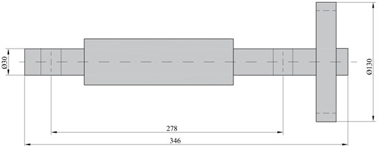
In this study, the research object was the rotor of an ORC turbine’s generator with an electric power of 30 kW. The analysis of the bearing system of the rotor shaft was conducted on the basis of the schematic diagram shown in Fig. 1. Based on the results of the calculations of the fluid-flow system, it was assumed that the rotor disc has a diameter of 130 mm (at the inlet) and each blade has a length of 15.4 mm. The nominal rotational speed of the rotor is 40,000 rpm. The shaft has a length of 346 mm whilst the bearing journals have a diameter of about 30 mm (as the matter of fact, this value was different for different bearing variants).
According to the design assumptions, the turbine generator is an oil-free device. For this reason, it was necessary to use the working medium of the thermal cycle in a liquid or gaseous form as a bearing lubricant. On the one hand, this limits the number of possible solutions of the bearing system, but on the other hand, it enables designing a very modern, compact and hermetically sealed construction.
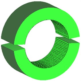
Fig. 1The basic dimensions of the microturbine rotor
3. Rolling bearings
The first bearing system, which was taken into account, employs rolling bearings. Based on the manufacturer’s information, bearings with a designation of “71906 CE/HCP4A” were picked [14]. These are angular ball bearings with a contact angle of 15° and a length of 9 mm, designed to support shafts with a diameter of 30 mm. The letters “HC” in the bearing denotation mean that balls are made of silicon nitride (Si3N4), and thus it is a hybrid bearing.
Hertz contact theory was applied to get stiffness coefficients of the bearing [15]. The stiffness coefficients of rolling bearings, used for the purposes of numerical analyses, are given in Table 1. The turbine generator’s fluid-flow system is designed in such a way that the axial load is as close to zero as possible. Therefore, the axial stiffness of the bearing was assumed to be 0 N/m.
Table 1Stiffness coefficients of rolling bearings used in the rotor dynamics analysis
Bearing designation | 71906 CE/HCP4A |
Stiffness ( and ) | 19·106 N/m |
Axial stiffness () | 0 N/m |
3.1. Numerical analysis of the rotor
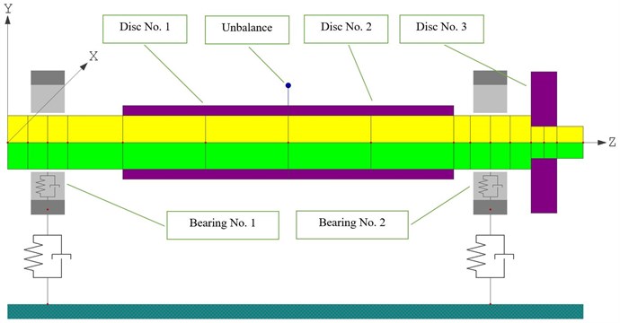
In Fig. 2 is presented the FEM model of the turbine generator, which was used in numerical simulations carried out for rolling bearings.
Fig. 2FEM model of the 30 kW ORC turbine’s generator with rolling bearings
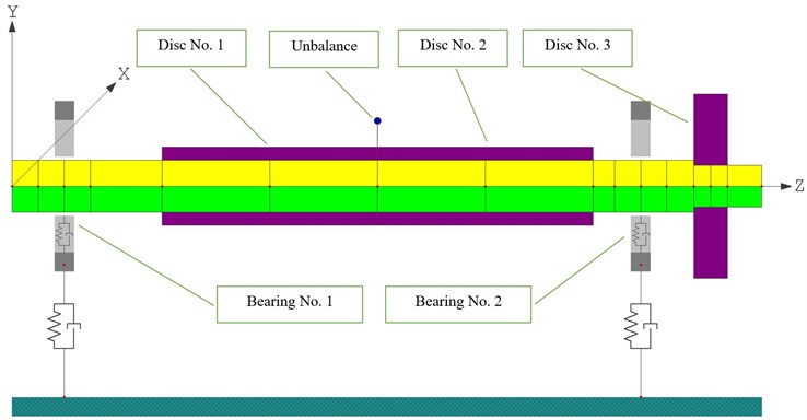
The FEM model, used in dynamic calculations, comprises 15 Timoshenko-type beam elements with 6 degrees of freedom at each node. The generator was modelled as two discs (Fig. 2), which are situated at shaft nodes No. 6 and No. 8 whilst the disc that is a counterpart of the turbine disc is located at shaft node No. 14. The rotor length is 346 mm.
All components of the system are made of steel with a density of 7,860 kg/m3. With these assumptions, the total mass of the rotor is 4.25 kg and the mass of the discs themselves is 2.39 kg. The kinetostatic load of the first bearing was 13.4 N and of the second was 28.3 N. The residual unbalance was 0.19 g at a radius of 22.5 mm (according to the ISO 1940-1 standard [16]), i.e. approx. 4.28 g×1 mm.
The stiffness coefficients, listed in Table 1, were used for the purposes of a rotor dynamics analysis of the microturbine with rolling bearings. A linear dynamic analysis of the system, in the rotational speed range of 1,000 rpm-100,000 rpm (with a step of 1,000 rpm), was conducted using the LDW computer program [17].
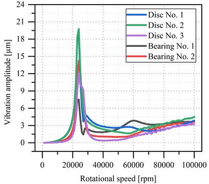
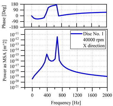
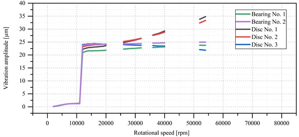
In Fig. 3(a) is shown the vibration amplitude as a function of the rotational speed of the microturbine’s rotor, for all nodes at which bearing journals and discs were modelled. The Power Spectral Density graphs, prepared using the mean squared amplitude (MSA) algorithm, are presented in Fig. 3(b). By looking at the upper graph, it can be observed how the phase changes as the frequency changes. The lower graph shows the amplitude versus the frequency. Both these graphs demonstrate the displacement of disk No. 1 at the nominal speed (40,000 rpm) in the direction. The highest amplitude values, which occured at frequencies of 389 Hz and 666 Hz, correspond respectively to the resonant speed and nominal speed. The curve that shows the phase of this signal passes through a value of zero degrees at a frequency of 389 Hz (in other words, at the resonant speed).
Fig. 3a) Vibration amplitude vs. rotational speed of the microturbine’s rotor supported by rolling bearings, b) power spectral density of disc No. 1 in X direction (horizontal)
a)
b)
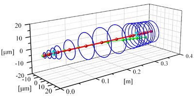
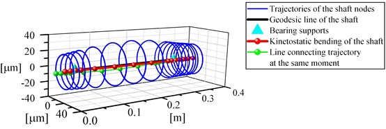
In Fig. 4 are depicted vibrations of the nodes of the shaft for two rotational speeds, namely, 25,000 rpm and 40,000 rpm. In the speed range of 24,000 rpm-29,000 rpm, the increased vibration level can be observed. The turbine operation at a speed that is higher than 24,000 rpm and lower than 29,000 rpm should be avoided if possible. In Fig. 4(b) are shown vibration trajectories obtained at the nominal rotational speed (40,000 rpm). These trajectories have a regular shape and the vibration amplitude does not exceed 3 µm. At a speed of 60,000 rpm, one can observe a slight increase in the vibration amplitude associated with vibrations of the shaft end, which is located at a considerable distance from the turbine disc. At this speed, the vibration amplitude does not exceed 4 µm.
Fig. 4Vibrations of the nodes of the shaft supported by rolling bearings with a diameter of 30 mm and a length of 9 mm for the following rotational speeds: a) 25,000 rpm, b) 40,000 rpm
a)
b)
Having conducted preliminary dynamic and strength analyses, it turned out that rolling bearings could be used in the ORC microturbine with an electric power of 30 kW. In comparison with the bearing systems described in the following sections of this article (liquid-lubricated and gas-lubricated bearings), the use of rolling bearings is the least costly solution. A major reason for this is that the manufacturing accuracy of the surfaces of rolling bearings’ journals is not so high as for the other two types of bearings. Nonetheless, the operation of the bearing system with rolling bearings could happen to cause a higher noise level at higher rotational speeds (due to the friction between the rolling elements and the bearing raceway). For longevity in high-speed bearings, one has to use either grease lubrication or air-oil lubrication. As far as hermetically sealed ORC systems are concerned, they have to be oil-free. It is, therefore, necessary to use dry (non-lubricated) bearings or bearing lubricated with vapours of a low-boiling liquid (usually with poor lubricating properties), which, as a result, may shorten the failure-free operation of such systems.
4. Liquid-lubricated slide bearings
The second analysed bearing system uses hydrodynamic slide bearings lubricated with a low-boiling liquid. Because the ORC system is oil-free, it is not possible to use traditional hydrodynamic bearings lubricated with oil. In this system, a certain amount of the working medium in its liquid state is used to power the bearings. Such a solution differs significantly from typical solutions known from energy machines with higher power capacities. It is due to the fact that low-boiling fluids used in ORC systems are characterised by much lower viscosity than typical oils used to lubricate bearings. Calculations were performed using computer programs belonging to the MESWIR system [17], which enable analysing rotating systems with slide bearings. The names of this programs are as follows: KINWIR-I – isothermal kinetostatic analyses, NLDW – non-linear dynamic analyses. Within the framework of kinetostatic computations, kinetostatic reactions of the bearing supports and positions of the journals were determined (at various rotational speeds), which then served as input data for non-linear dynamic computations.
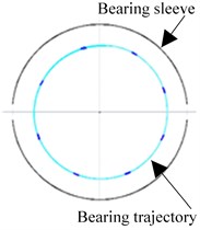
According to preliminary assumptions, the rotor was supported by two identical slide bearings lubricated with a low-boiling medium in its liquid state with a temperature of 46 °C. Four variants of the bearing system were analysed, in which such parameters as the bearing diameter, the bearing length, and the radial clearance were changed. In all variants, bearing sleeves had a cylindrical shape and consisted of two half-sleeves. The angular width of the interspaces between the half-sleeves was 10 degrees, as illustrated in Fig. 5.
Fig. 5The shape of the bearing sleeves, which was used in calculations of rotors supported by slide bearings
It was assumed that the rotor is made of steel with a density of 7,860 kg/m3. The total length of the rotor is 346 mm and is the same as in the previous case. Because the shaft mass had been changed, the value of the rotor unbalance was changed appropriately. The rotor was balanced according to the balancing class G 2.5 at a rotational speed of 40,000 rpm (in line with the ISO 1940-1 standard [16]) and the unbalance was 6.0 g·mm.
4.1. Numerical analysis of the rotor
In this section are presented calculation results obtained for the system equipped with hydrodynamic bearings whose diameter, length and radial clearance are respectively 40 mm, 20 mm and 30 μm. The rotating system’s FEM model is shown in Fig. 6.
Fig. 6FEM model of the turbine generator with hydrodynamic bearings
The total mass of the rotor is 5.98 kg and the mass of the discs themselves is 2.76 kg. The bearings are positioned at shaft nodes No. 3 and No. 11 and the distance between them is 278 mm. The kinetostatic load of the first (left) bearing was 21.7 N and of the second (right) was 36.9 N. The residual unbalance was calculated (according to the ISO 1940-1 standard [16]) as a mass of 0.218 g positioned with a radius of 27.5 mm, i.e. it was approx. 6.0 g·1.0 mm. The calculations were carried out in the following speed ranges: 1,000 rpm-20,000 rpm with a step of 1,000 rpm and 22,000 rpm-60,000 rpm with a step of 2,000 rpm.
Fig. 7Zero-to-peak vibration amplitude vs. rotational speed of the microturbine’s rotor supported by hydrodynamic bearings with a diameter of 40 mm, a length of 20 mm and a radial clearance of 30 μm
For a speed of 1,000 rpm, no convergence in the kinetostatic calculations was obtained, which means that lubricating films did not form themselves in the bearings. And what is more, no convergence was obtained in dynamic calculations for ten speeds (starting from a speed of 22,000 rpm), which indicates the unstable operation of the rotating system. The operation of the system at speeds from the range of 2,000 rpm-11,000 rpm was considered as stable and the maximum vibration amplitudes of all nodes were lower than 1.5 μm. At a speed of 12,000 rpm, vibration amplitudes of all nodes increased-staying in the range of 20 μm to 25 μm. As a matter of fact, these values are only slightly lower than the radial clearance (30 μm). In Fig. 8 are shown vibrations of the rotor at the nominal speed, namely, at a speed of 40,000 rpm.
Fig. 8a) Vibrations of the shaft nodes at a speed of 40,000 rpm, b) vibration trajectories of the journal of bearing No. 1 shown in relation to the radial clearance
a)
b)
Within the framework of the research described in this section of the article, many dynamic analyses of the ORC turbine with hydrodynamic bearings lubricated with a low-boiling fluid in its liquid state were conducted. The geometry of the bearings was optimised (bearing diameter, bearing length and the size of the lubrication gap) in order to obtain a properly operating turbine in terms of its dynamic performance. After all the analyses were conducted, it turned out that there had not been a case in which the operation of the rotor was stable enough to recommend this bearing system. Bearings running at higher rotational speeds, lubricated with low-boiling fluids, are successfully implemented in many currently operated ORC microturbines. As a matter of fact, ORC systems use different low-boiling operating mediums (with different viscosity) and hydrodynamic bearings are usually more loaded, which in this case positively affects the dynamic performance of the system.
5. Gas bearings
The last but not the least important of the analysed bearing systems employs aerodynamic bearings (lubricated with vapours of a low-boiling liquid). A certain amount of the low-boiling medium (operating in the thermal cycle) in the gaseous state is directed towards the bearings in order to power them. Even though such a solution lowers the efficiency of the entire ORC system (only very slightly), most importantly, it allows the ORC turbine generator to be both oil-free and hermetically sealed.
Calculations were carried out using computer programs belonging to the MESWIR system [17], used for analysing rotors supported by gas bearings. The programs have the following names: KINWIR-G (kinetostatic analyses) and LDW-G (linear dynamic analyses) [18]. Within the framework of kinetostatic analyses, kinetostatic reactions of the bearing supports and (at different rotational speeds) kinetostatic positions of the journals as well as stiffness and damping coefficients of the gaseous lubricating film were determined, which afterwards served as input data for linear dynamic computations.
According to preliminary assumptions, the rotor was supported by two geometrically identical aerodynamic bearings. In all calculations related to aerodynamic bearings, the vapour of the low-boiling medium, which had a temperature of 211 °C, was used as a lubricant.
All components of the rotating system were made of steel with a density of 7,860 kg/m3. The rotor length was 346 mm.
Exactly the same as for the systems with rolling and slide bearings, the magnitude of the residual unbalance of the rotor was in line with the ISO 1940-1 standard [16] and was calculated according to the balancing class G 2.5. According to the guidelines given in the standard, for a rotational speed of 40,000 rpm, the unbalance is 4.9 g·mm.
5.1. Analysis of the gas bearings’ capacity
It was investigated how much the diameter and length of the bearing affect the rotational speed at which the lubricating film forms itself. Calculations were made using the computer program named GAZBEAR, which belongs to the MESWIR environment [17]. The bearing was loaded with a force of 24 N. The calculations were performed for the following values of the radial clearance: 25 μm and 30 μm. There were analysed cases in which the length-diameter ratio of the bearing (/) was equal to or greater than 1.0 and equal to or lesser than 1.5 (1.0 ≤ / ≤ 1.5). The results obtained are presented in Fig. 9.
Fig. 9The minimum rotational speed at which the lubricating film forms itself vs. bearing length (for bearings with the following diameters: 34 mm, 36 mm, 38 mm and 40 mm)
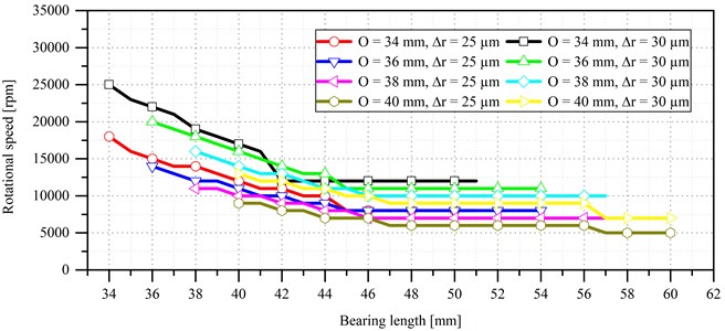
In all cases, better results were obtained for lower values of the radial clearance. However, a bearing with a length of 40 mm and a radial clearance of 25 μm could be technologically difficult to manufacture.
Having looked at the graphs, it can be said that the higher the bearing diameter the lower the speed at which the lubricating film formed itself. Furthermore, an increase in the bearing length also had a positive impact on the proper operation of the bearing (i.e. the lubricating film started to form itself at a lower speed).
5.2. Numerical analysis of the rotor
In Fig. 10 is presented the FEM model of the turbine generator with aerodynamic bearings whose diameter and length are the same and are equal to 40 mm. The difference with the previous numerical models is that the diameter of the bearing journals and of the surrounding beam elements is 40 mm. The external diameter of the generator is 45 mm. Because the shaft diameter increased significantly, the total mass of the rotor increased as well and is 5.98 kg whilst the mass of the discs themselves is 2.76 kg. The kinetostatic load of the first bearing is 21.68 N and of the second is 36.92 N. The distance between the bearings is 286 mm. As the value of the residual unbalance (according to the ISO 1940-1 standard [16]) a mass of 0.218 g with a radius of 22.7 mm (i.e. about 4.9 g·1mm) was adopted.
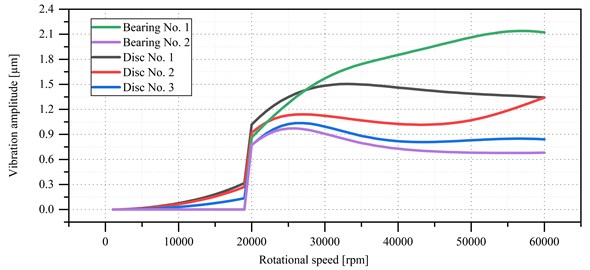
In Fig. 11 is presented a graph showing the vibration amplitude versus the rotational speed of the microturbine’s rotor. As can be seen in Fig. 11, the lubricating film occurred only after the speed was equal to 20,000 rpm, which is a worse result than that obtained in the bearing capacity test, where the bearing started to operate properly already at a speed of 13,000 rpm. This was due to the increase in the bearing load from 24 N to almost 37 N. Practically in the entire rotational speed range, the highest vibration level can be observed for the journal of bearing No. 1 (its highest vibration amplitude is 2.15 μm and occurs at a speed of 57,000 rpm). The journal of bearing No. 2 has the highest vibration amplitude (approx. 0.98 μm) at a speed of 25,000 rpm. Vibration amplitudes of the nodes at which discs were modelled did not exceed 1.5 μm for all tested rotational speeds.
Fig. 10FEM model of the turbine generator with aerodynamic bearings
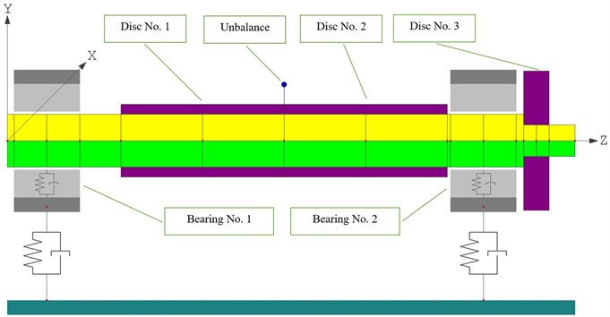
Fig. 11Zero-to-peak vibration amplitude vs. rotational speed of the microturbine’s rotor supported by aerodynamic bearings with a diameter of 40 mm, a width of 40 mm and a radial clearance of 30 μm
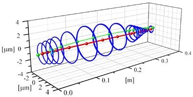
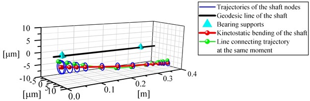
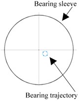
In Fig. 12(a) are presented vibrations of the nodes of the shaft at a rotational speed of 57,000 rpm, and that is the speed at which the vibration amplitude of the journal of the first bearing had the highest value. In spite of the fact that this is also the speed at which the vibration amplitude was the highest out of all tested rotational speeds, vibration trajectories of the journal of bearing No. 1 are small in size in relation to the radial clearance, as shown in Fig. 12(b).
Within the framework of the research described in this section of the article, it was checked whether the bearings lubricated with the vapour of a low-boiling medium could be used in the ORC microturbine. Firstly, it was investigated what is the lowest rotational speed for the formation of the lubricating film. It turned out that the gas bearing starts to operate properly (in other words, the lubricating film forms itself) when the microturbine's rotor rotates at a speed of about 10,000 rpm. Secondly, a dynamic analysis of the rotor supported by bearings lubricated with the vapour of a low-boiling medium was conducted. Similarly, as for the hydrodynamic bearings discussed in the previous section, the geometry of the bearings (bearing diameter, bearing length and the size of the lubrication gap) was optimised in terms of achieving the best dynamic performance. Unlike the system with hydrodynamic bearings, the system with gas bearings operates stably in the entire rotational speed range. All vibration amplitudes obtained during computational simulations were small and there were no subharmonic or superharmonic vibrations.
Fig. 12a) Vibrations of the nodes of the shaft supported by aerodynamic bearings at a rotational speed of 57,000 rpm, b) vibration trajectories of the journal of bearing No. 1 shown in relation to the radial clearance at the same rotational speed
a)
b)
6. Conclusions
In this article have been presented results of the analyses conducted for three bearing systems of the 30 kW ORC turbine generator’s rotor. The tested rotors were supported by rolling bearings, hydrodynamic bearings (lubricated with a low-boiling medium in the liquid state) and gas bearings (lubricated with a low-boiling medium in the gaseous state). To be able to handle harsh operating conditions, including the rotor’s rotational speed of 40,000 rpm, a high temperature of the microturbine’s working medium (above 200 °C) and low viscosity of the lubricating medium, the bearing system had to be analysed very thoroughly.
Numerical models of three bearing systems were created, which were then employed for carrying out calculations using computer programs belonging to the MESWIR system. These models consist of beam elements with appropriately modelled discs. In the middle of the generator, a residual unbalance was located, the value of which was carefully calculated for each analysed rotating system. The rotor disk was situated at one of the rotors ends. The properties of the bearings were put into the model in the form of stiffness and damping coefficients. As far as slide and gas bearings are concerned, the values of these coefficients were dependent on the rotational speed.
Based on the results of the analyses of various bearing systems for the ORC turbine generator’s rotor, it can be concluded that each of these systems has some drawbacks and advantages. The most important conclusions arising from the conducted research are as follows:
1) Based on constructional requirements, rolling bearings with a designation of “71906 CE/HCP4A” were chosen. These are angular contact super-precision ceramic bearings with balls made of silicon nitride (Si3N4), and thus they are hybrid bearings. The stiffness of such a bearing was calculated and afterward the dynamic properties of the turbine generator’s rotor supported on such bearings were investigated.
The results obtained from the analysis of the bearing system with rolling bearings show that in the tested rotational speed range a resonant speed (about 23,000 rpm) was observed. At that speed, the maximum vibration amplitude was 20 µm. For the sake of comparison, the vibration amplitude did not exceed 4 µm at the nominal speed. It can, therefore, be concluded that rolling bearings could be used in the bearing system for the turbine generator’s rotor.
2) The second variant of the bearing system uses slide bearings lubricated with a low-boiling medium in the liquid state. The FEM model was developed, which allowed analysing bearings with different geometries. At some rotational speeds in the range of 10,000-12,000 rpm (depending on the bearing geometry), an abrupt increase in the vibration level occurred. Moreover, there were signs of hydrodynamic instability, which meant that the bearings did not operate properly. None of the investigated bearing systems guaranteed both a reliable operation at speeds equal to or lesser than the nominal speed and a long service life.
3) The third variant of the bearing system makes use of gas bearings lubricated with the vapour of a low-boiling medium. Similarly, as for the previous bearing systems, a FEM model was developed, and a series of calculations was carried out. During analyses, gas bearings with various geometries were considered. Such parameters as the bearing diameter, the bearing length and the size of the lubrication gap were altered.
Based on the obtained results, the conclusion can be made that it is possible to properly select the geometry of the gas bearings in order to provide the required bearing capacity at low rotational speeds (starting from around 10,000 rpm) and guarantee a stable and reliable operation at high rotational speeds (including the nominal speed).
One should also note that during the operation of the turbine generator with gas bearings, there are potential issues that may arise in connection with a too high temperature of the generator itself as the bearings are located very close to it. The temperature of vapour of the working medium directed to the stator blades of the microturbine is 211°C. Feeding the bearings with the vapour of such a high temperature will cause an increase in the temperature inside the turbine generator’s casing, and hence a decrease in the efficiency of the generator. In the worst case scenario, a too high temperature may cause the generator to malfunction (and it could stop generating electricity).
Based on the results obtained from kinetostatic and dynamic analyses, it can certainly be stated that gas bearings could be components of the bearing system of the turbine generator’s rotor.
On the basis of the analyses conducted so far, the conclusion can be made that gas bearings fed with the vapour of a low-boiling medium are the most prospective bearing system for the ORC turbine’s generator with an electric power of 30 kW. In this bearing system, there is a need to ensure additional cooling of the electric generator in order to avoid its overheating. Results of the performed calculations justify the supposition that high-speed rolling bearings could be used as well. But, if that would be the case, an elevated vibration level could occur in some rotational speed ranges, resulting from the existence of poorly damped resonances of the rotor. If rolling bearings will operate under such harsh conditions, their service life will be shortened. Even though the solution that uses rolling bearings seems to be the least costly and is the simplest way to create the bearing system of the ORC turbine generator’s rotor, gas bearings seem to be more suitable for series production.
References
-
Lecompte S., Huisseune H., Van Den Broek M., Vanslambrouck B., De Paepe M. Review of organic Rankine cycle (ORC) architectures for waste heat recovery. Renewable and Sustainable Energy Reviews, Vol. 47, 2015, p. 448-461.
-
Song P., Wei M., Shi L., Danish S. N., Ma C. A review of scroll expanders for organic Rankine cycle systems. Applied Thermal Engineering, Vol. 75, 2015, p. 54-64.
-
Kaczmarczyk T. Z., Żywica G., Ihnatowicz E. The impact of changes in the geometry of a radial microturbine stage on the efficiency of the micro CHP plant based on ORC. Energy, Vol. 137, 2017, p. 530-543.
-
Mounier V., Olmedo L. E., Schiffmann J. Small scale radial inflow turbine performance and pre-design maps for organic rankine cycles. Energy, Vol. 143, 2018, p. 1072-1084.
-
Żywica G., Drewczyński M., Kiciński J., Rządkowski R. Computational modal and strength analysis of the steam microturbine with fluid-film bearings. Journal of Vibrational Engineering and Technologies, Vol. 2, Issue 6, 2014, p. 543-549.
-
Żywica G., Kaczmarczyk T. Z., Ihnatowicz E., Turzyński T. Experimental investigation of the domestic CHP ORC system in transient operating conditions. Energy Procedia, Vol. 129, 2017, p. 637-643.
-
Sung T., Yun E., Kim H. D., Yoon S. Y., Choi B. S., Kim K., Kim K. C. Performance characteristics of a 200-kW organic Rankine cycle system in a steel processing plant. Applied Energy, Vol. 183, 2016, p. 623-635.
-
Tkacz E., Kozanecki Z., Kozanecka D. Numerical methods for theoretical analysis of foil bearing dynamics. Mechanics Research Communications, Vol. 82, 2017, p. 9-13.
-
Żywica G., Kiciński J., Bagiński P. The static and dynamic numerical analysis of the foil bearing structure. Journal of Vibrational Engineering and Technologies, Vol. 4, Issue 3, 2016, p. 213-220.
-
Żywica G., Bagiński P., Breńkacz Ł., Miąskowski W., Pietkiewicz P., Nalepa K. Dynamic state assessment of the high-speed rotor based on a structural-flow model of a foil bearing. Diagnostyka, Vol. 18, Issue 1, 2017, p. 95-102.
-
Bagiński P., Żywica G., Lubieniecki M., Roemer J. The effect of cooling the foil bearing on dynamics of the rotor-bearings system. Journal of Vibroengineering, Vol. 20, Issue 2, 2018, p. 843-857.
-
Lee H. G., Shin J. H., Choi C. H., Jeong E., Kwon S. Partial admission effect on the performance and vibration of a supersonic impulse turbine. Acta Astronautica, Vol. 145, 2018, p. 105-115.
-
Bini R., Colombo D. Large multistage axial turbines. Energy Procedia, Vol. 129, 2017, p. 1078-1084.
-
Super-Precision Bearings. Catalog SKF, 2013.
-
Krzemiński Freda H. Rolling Bearings. 2nd ed., Państwowe Wydawnictwo Naukowe, Warsaw, 1989, (in Polish).
-
ISO 1940-1 Mechanical Vibration – Balance Quality Requirements for Rotors in a Constant (Rigid) State. Part 1: Specification and Verification of Balance Tolerances, 2003.
-
Kiciński J. Dynamics of rotors and slide bearings. IMP PAN, Maszyny Przepływowe, Gdańsk, 2005, (in Polish).
-
Banaszek S., Zywica G., Kicinski J., Bogulicz M. The dynamics of the laboratory rotor founded on the gas foil bearings-numerical analysis. Proceedings of the 9th IFToMM International Conference on Rotor Dynamics, Vol. 21, 2015, p. 1235-1246.
About this article

This work has been funded by The National Centre for Research and Development from The Smart Growth Operational Programme (European funds) within the Project No. POIR.01.01.01-00-0512/16 carried out jointly with the Marani Sp. z o.o. company.
