Abstract
Advances in the development of analysis and design methods for fluid-flow machines have enabled both their multi-criteria optimisation and miniaturisation. To decrease the size of such a machine whilst, at the same time, maintaining its output power level, the rotor’s rotational speed needs to be increased. It is the reason for serious difficulties with respect to the rotor dynamics and the selection of a bearing system. This article discusses the simulation analysis and experimental research carried out on a prototypical microturbine, designed for use in a domestic ORC (organic Rankine cycle) cogeneration system. During the design process, the basic assumption was to develop a turbomachine, whose dimensions would have been as small as possible and whose output electric power would have been about 1 kilowatt. A supersonic impulse turbine, with a nominal rotational speed of 100,000 rpm, was used in order to obtain high flow efficiency. The maximum speed of the rotor was determined at a level of 120,000 rpm. The article presents the results of analyses made at the design stage and preliminary results of the experimental research. The numerical simulations covered the bearing system optimisation and the rotor dynamics analysis. Next, based on the outcomes of these analyses, a decision was made to use non-conventional gas bearings which are fed by the low-boiling medium’s vapour that comes from the ORC system. Within the framework of the experimental research, the dynamic behaviour of the turbogenerator was examined in terms of the rotational speed and produced energy. The performed measurements are proof of very good dynamic properties of the tested machine and after the research was over it was concluded that there were absolutely no signs of wear of the turbogenerator’s subassemblies.
Highlights
- Investigation of an energetic microturbine with unconventional gas bearings and a maximum rotational speed of 120 krpm is presented
- Numerical analysis including the bearing-system optimisation was made
- Vibrations of the 1-kilowatt microturbine were tested experimentally
- Results of numerical predictions and experimental tests have been compared
1. Introduction
The development of novel analysis and design methods for turbomachines gives us various possibilities to optimise them. It allows us to reduce their dimensions whilst increasing their efficiency. Such machines are widely used in many industrial branches, such as armaments industry, transportation and power engineering. This article discusses the research carried out on an innovative vapour microturbine which may be considered as a power machine. Fluid-flow machines of this type are increasingly used in the production of electricity, in situations where large centralized sources of thermal and electrical energy are replaced by a greater number of small, locally available energy sources (the so-called distributed cogeneration) [1].
An increasing interest in small systems, which allow the production of heat and electricity, is closely linked to favourable conditions for the development of distributed power engineering. Besides the possibilities for the use of energy resources available at a local level (renewable energy sources and non-renewable fuels), another practical advantage is that there are no losses related to the transmission of electric energy, which also gives breathing space to consider the long term usage of the national power grid. Distributed power engineering has little influence on the natural environment and helps to reduce greenhouse gas emissions [2, 3]. Of various cogeneration technologies available on the market, ORC (organic Rankine cycle) systems have gained in popularity in recent years. Such systems can make use of renewable energy sources (for example, geothermal heat, solar energy or biomass) and classic fossil fuels (coal or natural gas) [4]. ORC systems can also be fed with waste heat coming from industrial processes or combustion engines [5]. For electricity generation in such systems, various types of volumetric and dynamic expanders [6] can be used, such as screw expanders, scroll expanders [7], piston expanders [8], vane expanders [9] or turbine expanders [10]. In micro-power ORC systems, microturbines of different types are increasingly used as expanders [10-12]. The reasons for this are their small dimensions and many possibilities of designing flow systems. It allows for obtaining high efficiencies with various low-boiling working mediums [13]. Gas microturbines have already been used many times in cogeneration systems [14] as it seems like there are no alternative solutions other than combustion engines and fuel cells. Compared to reciprocating engines, gas microturbines are characterised by low weight, small dimensions, high durability and low operating costs [15]. Due to the considerable design similarity, vapour microturbines used in ORC systems share some common features with gas microturbines [16].
Modern vapour microturbines used in ORC systems are usually designed as machines with one rotor. It means that the rotor disc and the generator are mounted on the same shaft. Such a solution results in a compact design and the rotor is the only movable component in such microturbines. This improves both their durability and reliability. Compared to microturbines whose generators are driven via reduction gears, losses related to the transmission of kinetic energy are not present in the microturbines discussed herein. The high-speed generator is a very significant element in each energy microturbine with one rotor [17, 18]. It has to meet a number of technical requirements, the most important of which include the ability to operate at high rotational speeds, resistance to high temperature and the working medium. Bearings are also considered as key elements of microturbines. When a lubricant is present inside a microturbine it can contaminate the working medium; therefore, the so-called oil-free technology seems to be the best choice [19, 20]. The bearings of oil-free turbogenerators are usually lubricated with the working medium (in the form of vapour or liquid) coming from the ORC system. However, when doing so, an unconventional bearing system has to be used [21, 22].
Foil bearings are one of the solutions adopted in modern bearing systems for the purposes of supporting high-speed rotors [23]. Such bearings do not require an external lubrication system; air or another substance that is present in their immediate vicinity can be used as a lubricating medium. Compared to rolling element bearings [24], which are very popular, foil bearings are characterised by high durability and good vibration-damping capability. In modern turbomachines, magnetic bearings are also used, in particular, active magnetic bearings [25]. Most of such bearings are active magnetic bearings, using electromagnets which require an active control system to operate. Due to the high cost of such an active control system, active magnetic bearings are very rarely used in small turbomachines. The use of magnetic fluid bearings (that is to say, slide bearings in combination with magnetic fluids) is a novelty in bearing system technologies [26]. By using ferrofluids for lubrication of a bearing, it is possible to control (to a certain extent) the properties of the bearing node during operation [27]. Bearings of this type are not used often. Of all available types of bearing systems that can be used in fluid-flow machines (including ORC microturbines), gas bearings and high-precision rolling element bearings (whose rolling elements are made of ceramic materials) are most frequently applied in practice. Depending on the operating conditions, gas bearings can be designed as aerodynamic (self-acting) or aerostatic (fed using an external system).
This article discusses the research done on a prototypical ORC microturbine, which had been designed for operation in a domestic cogeneration system. The subsequent parts of the article present the following issues: characteristics of the developed machine, the discussion of results of the numerical simulations aimed to choose an optimal bearing system and an analysis of the dynamic performance of the rotor. Next, there are presented the results of vibration measurements, carried out during the microturbine operation at various rotational speeds and power levels. The research presented herein was focused on improving knowledge of the dynamic properties of the rotating system applied to a new high-speed turbomachine.
2. Characteristics of the high-speed microturbine
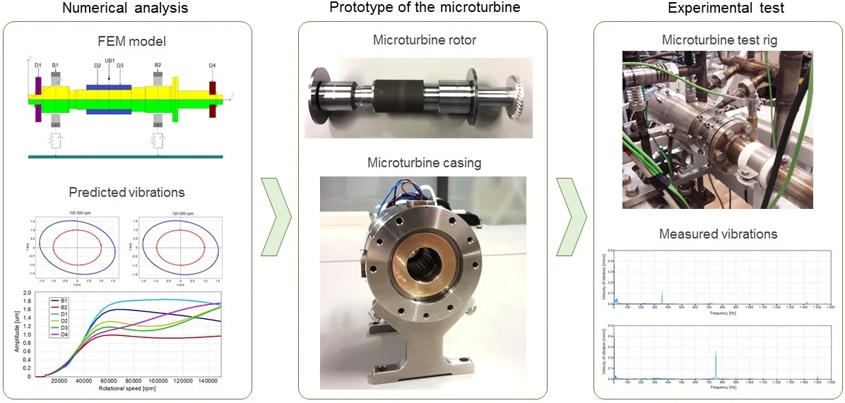
The ORC microturbine with the nominal electric power of 1 kW was the object of research discussed in this article. It was designed and built at the Institute of Fluid Flow Machinery, Polish Academy of Sciences (IMP PAN), in Gdansk, under the framework of an R&D project carried out in cooperation with an industrial partner. The microturbine was adapted to be coupled with a heating boiler, whose thermal power can be in the range from 15 kW to 20 kW. The combination of a specifically developed microturbine with the boiler using an ORC system allowed us to build the cogeneration system which makes it possible to heat a house and water and also produce electric energy. The produced energy can be used up on-site or transmitted to the power grid. A single-stage axial-flow impulse microturbine is the key component of the machine developed. Various low-boiling liquids can be employed in the microturbine as a working medium, including HFE-7100, which is a non-combustible environmentally-safe substance. At the nominal operating point, the microturbine operates at the supply pressure of 10.3 bar and the working medium temperature of 150 °C. The rated flow of the working medium is 25 g/s. Due to the very low flow rate of the working medium, the microturbine rotor has to operate at a very high rotational speed; the maximum value is 120,000 rpm. Despite the fact that the newest publications discuss energy microturbines with a similar power level [28], the developed microturbine is characterised by its very high rotational speed and small dimensions. A sectional view of the microturbine, on which the basic subassemblies are marked, is shown in Fig. 1.
Fig. 1A cross-sectional view in the horizontal plane of the ORC microturbine
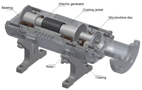
The microturbine disc is placed at the free end of the shaft whilst the generator rotor is located at the middle part of the shaft between the two bearings. The generator stator, embedded in the casing, is cooled using a cooling jacket. The rotor disc and the generator rotor are situated on the same shaft, as are the two keep plates of the thrust bearings. Two radial-axial gas bearings (fed by the working medium’s vapour) were employed to support the shaft. It made it possible to build the oil-free micro-turbogenerator. The labyrinth seal separates the flow part of the machine from the generator part; none the less, leakages between these two sections are permissible as the same working medium is present in them.
3. Numerical analysis
As already the preliminary analyses had shown that the microturbine rotor will have to operate at a very high rotational speed, a detailed analysis of the rotating system was necessary at the design stage. The thorough analysis covered both the selection of the bearing system and its optimisation as well as the dynamic performance of the rotor at various rotational speeds. Due to nontypical operating conditions of the rotor and also due to the opportunity of using one of the nonconventional bearing systems, the in-house developed computer programs – being a part of the so-called MESWIR series [29] – were used for the calculation purposes.
3.1. Selection of the bearings
During the preliminary analysis of the bearing system for the microturbine rotor, the following solutions were considered: rolling element bearings, gas bearings and foil bearings. Each of these solutions has its advantages and disadvantages, some of which are briefly discussed below.
Rolling bearings are most frequently used in small fluid-flow machines as they are readily available in the market at low prices. Such bearings require lubrication, which is a disadvantage in the present case and is incompatible with the concept of the oil-free machine. The permissible rotational speed of rolling bearings is strictly related to the journal diameter (more specifically, is related to the circumferential speed of the rolling elements). It was determined that when the bearings’ journals had a diameter of 8 mm it was possible to obtain the maximum rotational speed at the level of 120 krpm [30]. Such a low diameter at the supporting points of the shaft significantly decreases its stiffness, thereby lowering the critical speed of the rotor below the nominal speed. At the resonant speed, operation of the rotor supported by rolling bearings is not safe due to large displacements [31]. Therefore, a decision was made to relinquish the use of rolling bearings.
The main advantages of foil bearings, in the discussed case, are the ability of stable operation of the rotor at very high rotational speeds and no necessity for oil lubrication. Their major disadvantages are low accuracy of the rotor alignment, high starting torque and power losses related to it [32]. The low precision alignment requires the application of higher clearance above the blades in the microturbine, which decreases the efficiency of the flow system. Due to these aspects the use of the foil bearings was abandoned. As the analysed rotor was characterised by high stiffness and good dynamic properties, there was no need to apply such an advanced solution as foil bearings.
After preliminary analyses, taking into account the advantages and disadvantages of various bearing systems, it was decided to use gas bearings fed by the microturbine’s working medium. Such bearings allow to develop machines using the oil-free technology, enable to obtain very high rotational speeds and low friction losses. Their disadvantages are low bearing load capacity and the possibility of damage at low rotational speeds (i.e. before a stable gaseous lubricating film is formed). To prevent damage to the sliding surfaces, it was decided to lubricate the bearings with a gaseous lubricating medium under pressure. The medium gets into the bearings through small diameter holes, evenly spaced over the circumference of the sleeve. In the ORC system, the fresh vapour (which evaporated in the evaporator before the microturbine) can be used to lubricate the bearings. In the discussed case, the working medium’s vapour at the evaporator outlet has a pressure greater than 10 bar, and its low consumption by the bearings should not have a significant impact on the microturbine power. The estimated vapour consumption in all bearings does not exceed 5 per cent of the total flow rate in the ORC system. In the case of a higher demand for vapour in the ORC system, the flow rate in the circulation pump can be increased without changing other parameters of the cycle.
The calculations, aimed at the selection of all dimensions of the bearings, were carried out using the MESWIR series computer programs that enable analyses of aerodynamic gas bearings. In these calculations, parameters of the low-boiling medium used for lubrication of the bearings were taken into account, but the fact that the bearings are fed was not considered. In this way, only aerodynamic phenomena stemming from the geometry of the bearings, rotational speed and viscosity of the lubricating medium were taken into account. The characteristics of the bearings were determined on the basis of an isothermal model of an aerodynamic gas bearing. Static analysis consists in determining the reaction force of a gaseous film to a given static load. During calculations the following equations are solved: Navier-Stokes momentum equation (assuming that there is constant pressure in the direction corresponding to the lubricating film thickness) and equation of continuity (with no mass transfer). The pressure distribution of the lubricating film is determined based on the Reynolds equation for compressible fluids in the following form:
where: – gas pressure, – gas density, – radial clearance, and – the radial coordinate and the angular coordinate of the polar coordinate system, – gas viscosity, – bearing length, – angular speed.
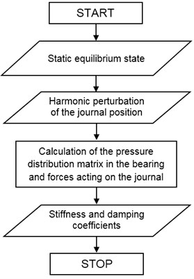
Dynamic analysis consists in calculating the stiffness and damping coefficients at the considered operating point of the gas bearing (which is taken based on the results of the static analysis). The simplified algorithm for dynamic calculations is presented in Fig. 2. Calculations are performed in the local coordinate system and then transferred to the global coordinate system of the bearing.
Fig. 2Simplified algorithm for calculating the dynamic coefficients of gas bearings
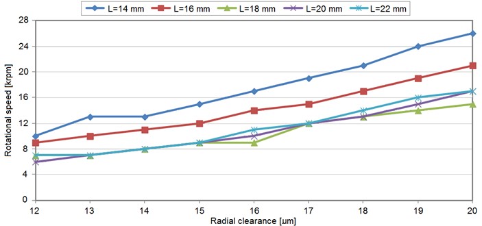
During the calculations, the focus was on assessing the operating conditions of gas bearings with different diameters, lengths and radial clearance. The diameter of the bearing was analysed in the range from 16 mm to 24 mm, its length in the range from 14 mm to 22 mm and its radial clearance in the range from 12 µm to 20 µm. Over 200 variants of the bearing’s dimensions were analysed in this way. Due to the uneven loading of the two bearings, the search area for the best solution was expanded to include cases in which each of the two bearings has different dimensions. The exemplary calculation results, in the form of characteristics showing the effect of length and radial clearance of the bearing with a diameter of 20 mm on the lift-off speed, are presented in Fig. 3. In this case, the static load of the bearing was 2.3 N. Having the lift-off speed calculated, it is known that the bearing with given dimensions, at a given speed, has the capacity to carry the static load. A lower lift-off speed at a given load is favourable as it enables stable operation of the gas bearing (even if it is not fed with the lubricating medium).
On the basis of the performed analyses, it was determined that the microturbine rotor is characterised by stable operation in a wide range of rotational speeds when it is supported on the gas bearings with a diameter of 24 mm and a length of 22 mm. The optimal value of the radial clearance is 20 µm, which is the highest value out of all the analysed ones. This choice was also influenced by practical considerations related to the manufacturing technology and manufacturing precision of the journal and of the sleeve. Due to the small benefits resulting from using two bearings with different dimensions, two identical bearings were selected. The lift-off speed of the chosen bearing is about 8,000 rpm at the load resulting from the rotor mass. It means that this bearing can be considered as aerodynamic when it operates at speeds that are higher than the lift-off speed. At lower speeds, this bearing has to be fed with the lubricating medium under pressure.
Fig. 3Lift-off speed in the gas bearing (with a diameter of 20 mm), which was loaded by a force of 2.3 N vs radial clearance; for five different values of the bearing length
3.2. Rotor dynamics analysis
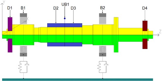
The selection of the bearing system made it possible to perform the rotor dynamic analysis. The purpose of this analysis was to determine critical speeds of the rotor and to check the vibration level at different rotational speeds. For this purpose, an FEM model of the rotor was developed, taking into account the characteristics of the selected gas bearings lubricated with a low-boiling medium. A graphical representation of the model is presented in Fig. 4. It includes the generator rotor (blue colour), the rotor disc (red colour) and two keep plates of the thrust bearings. The total length of the rotor was 175 mm and both bearing journals had a diameter of 24 mm. The distance between the bearing centres was 92 mm. The following assumptions were applied to the numerical model: the shaft and keep plates of the thrust bearings are made of 1.7225 alloy steel, the microturbine’s rotor disc is made of 7075 aluminium alloy. The mass of the complete rotor was approximately 0.6 kg.
Fig. 4The FEM model of the rotor of the ORC microturbine with an electric power of 1 kW (D – discs, B – bearings, UB – unbalance)
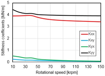
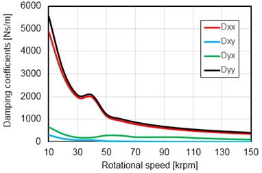
Calculations were made for speeds up to 150,000 rpm. Their purpose was to check if there are any resonant speeds within the operating speed range or slightly higher than the maximum speed (120,000 rpm). During the rotor dynamics analysis, the characteristics of the journal bearings were taken into account. These characteristics were determined in the form of stiffness and damping coefficients for all analysed rotational speeds. Such characteristics for less loaded bearing (B1) are presented in Fig. 5. The curves representing the values of the stiffness and damping coefficients of the second bearing (B2) were very similar. Next, the coefficients were incorporated into the FEM model of the rotor (their values changed as the analysed rotational speed changed). Such an approach allowed to obtain more reliable results than for constant values of the stiffness and damping coefficients.
Fig. 5a) Stiffness and b) damping coefficients of gas bearing (B1)
a)
b)
For the purposes of the forced vibration analysis, the maximum permissible unbalance of the rotor was adopted on the basis of the ISO1940 standard. It was placed in the middle of the generator sleeve, at the node where the highest vibration level was expected. The unbalance is marked as “UB1” in Fig. 4. Such positioning of the unbalance allow to excite bending vibration of the rotor in order to calculate its first critical speed.
Fig. 6Vibration amplitudes of the microturbine rotor, calculated in the wide rotational speed range
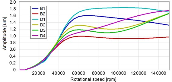
The calculation results are presented in Fig. 6, in the form of vibration amplitudes of the bearings and discs versus the rotational speed of the rotor. The graph shows absolute vibration of the discs and relative vibration of the bearings (in other words, the vibration of the journals in relation to the bearing sleeves). It can be noticed that the vibration of the system increased as the rotational speed increased (up to a speed of approximately 60 krpm). The maximum vibration level (approx. 1.8 µm) was observed for the keep plate of the thrust bearing, located at the shaft end (D1). The bearings had the following maximum vibration amplitudes: the first bearing (B1) – 1.6 µm, the second bearing (B2) – 1 µm. At a speed of 60 krpm, the vibration amplitude calculated in the middle of the rotor (i.e. where the generator is mounted – D2) was 1.3 µm. At higher speeds, the vibration amplitude at the first bearing (B1) decreased gradually; at the second bearing (B2), it was more or less at the same level. As far as the keep plate of the thrust bearing is concerned (D1), the vibration level changed slightly as the speed increased more. For higher rotational speeds, the vibration of the generator decreased and then increased to a value of 1.7 µm. In the speed range from 60 krpm to 150 krpm, the highest increase in the vibration level can be noticed for the rotor disc (D4); at a speed of 60 krpm, the vibration amplitude was 1.1 µm and it increased to 1.8 µm at a speed of 150 krpm. Generally speaking, the level of vibration of the analysed rotor was very low as it did not exceed 2 µm in the whole speed range. Additionally, on the basis of the calculation results, it can be stated that the first critical speed of the rotor was outside the range of operating speeds; this speed was approximately 200 krpm. The overall low vibration level and such a high value of the first critical speed (i.e. beyond the range of operating speeds) indicate that the rotor–bearings system has very good dynamic properties. Other calculation results, for instance, vibration trajectories (Fig. 7) and vibration velocity spectrums, are also proof that the rotor supported on two gas bearings is characterised by very good dynamic performance. Within the entire rotor operating range analysed, only forward whirls were observed. Since the positive calculation results were obtained, it was possible to build the machine and test it.
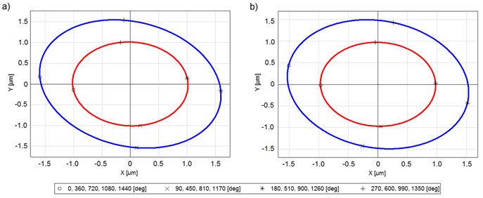
Fig. 7Vibration trajectories of bearing journals at a) 100 krpm and b) 120; (blue line – bearing 1, red line – bearing 2)
4. Experimental tests
4.1. Test rig description
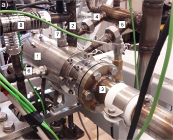
The experimental research on the prototypical ORC microturbine was carried out in the laboratory at the IMP PAN. After finishing the preparatory work, the microturbine was installed on a specialised test rig (Fig. 8(a)). The test rig makes it possible to simulate the real operating conditions of the machine when coupled with an ORC system. The microturbine and its bearings were fed with the fresh vapour of the working medium sold under the trade name of HFE-7100, and the vapour that was already used was directed to a set of heat exchangers, which enabled to obtain the specified temperature and pressure. At the microturbine inlet, the working medium reached a pressure of 13.5 bar and a temperature of 180 °C. The flow rate of the working medium was controlled using a circulation pump with adjustable rotational speed. In the ORC system in question, an electric heater served as a heat source.
Because a direct vibration measurement of the rotor would have required making additional holes for sensors in the casing, which could have caused unwanted leakage of the low-boiling medium, the vibration was measured on the microturbine casing. A vibration sensor was fixed to the upper part of the casing using a magnetic pad, in the vicinity of the bearing situated between the rotor disc and the generator (Fig. 8(b)). As the microturbine casing was made of stainless steel, in order to mount the sensor it was necessary to use a ferromagnetic mounting pad screwed in the casing. The vibrations were measured using a uniaxial accelerometer (PCB HT628F01), tailored to work at an elevated temperature. A portable machine health analyser MBJ Diamond 401A (in its most extended version denoted by XT) was used to record the results. Besides the vibration measurement during operation of the microturbine, the following parameters were also measured: rotational speed of the rotor, electric power of the generator and thermodynamic parameters of the working medium. These additional measurements were carried out using a separate measurement system.
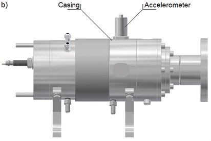
Fig. 8a) The prototypical microturbine installed on the test rig and b) its model showing where an accelerometer was mounted (1 – microturbine, 2 – turbine inlet, 3 – turbine outlet, 4 – bearing 1 inlet, 5 – bearing 2 inlet, 6 – horizontal accelerometer, 7 – vertical accelerometer, 8 – pressure sensor)
4.2. Measurement of vibrations
During the conducted research, the maximum electric power of the turbogenerator was about 1.1 kW, which was achieved when the rotor’s speed was at the level of 60 krpm. Due to limitations related to the efficiency of the circulation pump and difficulties with achieving a higher pressure and a higher flow rate of the working medium, no tests were done at speeds higher than 60 krpm. The favourable characteristics of the working medium made it possible to achieve the nominal electric power (1 kW) already at a speed of 56 krpm. If other low-boiling mediums (intended for this microturbine) were used, the nominal power could have been achieved at higher rotational speeds.
The vibration measurement results are presented in Figs. 9-13. Of all the results, several vibration velocity spectrums were chosen. These characteristics were obtained when the operating conditions of the microturbine were stable. In this case, it means that the rotor had a constant speed for at least 30 seconds and there were no changes in the pressure, temperature and flow rate of the working medium. The vibration velocity spectrums shown in Figs. 9-12 cover the frequency range from 1 Hz to 1,600 Hz whilst the vibration velocity spectrum demonstrated in Fig. 13 covers the range from 2 Hz to 3,200 Hz. The measuring range on the last graph was extended due to the necessity to register the rotational frequency component 2. If the rotational speed was greater than 48 krpm, the component 2 occurred at a frequency that was higher than 1,600 Hz. The measurement resolution in the frequency range from 1 Hz to 1,600 Hz was 1 Hz and after the frequency range was extended it was equal to 2 Hz. The reduction of the measurement resolution for the extended frequency range was necessary due to the capabilities of the measuring apparatus. Additional vibration measurements, performed for even more extended frequency range (up to 25,600 Hz), did not show the necessity of further extending the measuring range.
In order to facilitate making a comparison of the results presented in Figs. 9-13, all the axes of ordinates have the same scale with a maximum value of 0.5 mm/s. It should be noted that on each of the graphs one can distinguish three areas with an elevated vibration level. The first area covers the range of very low frequencies, namely the range from a minimum frequency to about 50 Hz. These vibrations are not related to operation of the microturbine and come both from the operation of other devices located in the laboratory (e.g. pumps, fans) and from the movement of people that were present in the lab during the measurements; the laboratory is located on a wooden platform supported on steel pillars. Since exciting forces coming from these sources have different frequencies, the vibration distribution is quite random in the range of low frequencies. The next area, in which an increased vibration level can be observed, is related to vibration of the rotating shaft. In this case, the vibration frequency is equal to the rotational frequency of the rotor (therefore it is denoted as 1) and in Figs. 9-13 it takes the following values: 202 Hz, 355 Hz, 627 Hz, 749 Hz and 932 Hz. At these frequencies, one could observe a distinct vibration component, whose vibration velocity was high. The vibration amplitude increased as the rotational speed increased and had the following values: 0.107 mm/s, 0.124 mm/s, 0.138 mm/s, 0.265 mm/s and 0.303 mm/s. Taking into account the calculation results presented in the previous chapter, one can notice that these results are in good agreement with the experimental results. In both cases, the level of vibration originating from the rotor increased as the rotational speed increased. Bearing in mind the obtained calculation results, one can expect that at higher rotational speeds (over 60 rpm) vibration of the microturbine should not increase more but remain on the same level. On all graphs showing the vibration velocity spectrums, the third area with an increased vibration level occurs at a frequency that is two times greater than the rotational frequency of the rotor. This is vibration (denoted by 2) in which the shaft gives 2 times the fundamental frequency in one revolution. In the case of the ORC microturbine, the amplitude of the 2 component was very low; it was at least 3 times lower than 1 component in the whole range of rotational speeds. Such vibration of a rotating system can be a result of misalignment or bending of the shaft, and may be caused by non-uniform heating and some temperature gradient in the shaft. Because in the case of the discussed machine the level of this vibration was very low, it was not analysed more widely.
Fig. 9Vibration velocity spectrum of the microturbine casing at a speed of 12,120 rpm (202 Hz)
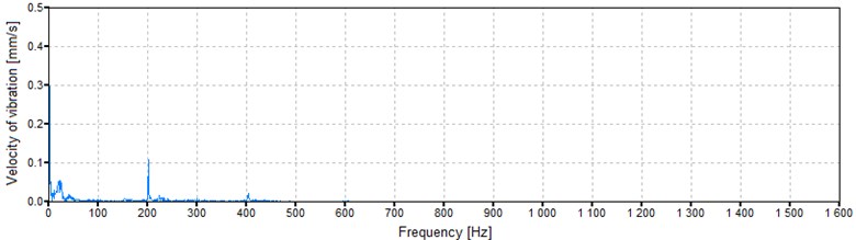
Fig. 10Vibration velocity spectrum of the microturbine casing at a speed of 21,300 rpm (355 Hz)
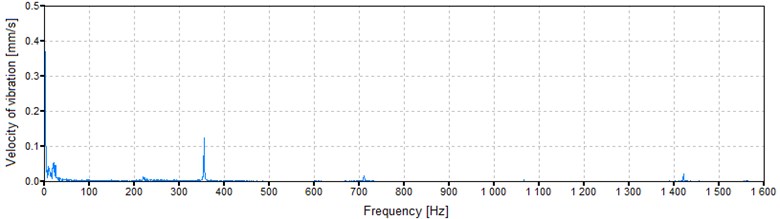
Table 1 includes the measurement results presented in Figs. 9-13 as well as the ones obtained for three additional rotational speeds. These additional results were also obtained when the operating conditions were stable. The presented results are proof that the amplitude of the 1 vibration component increased as the rotor speed increased in the entire investigated range of speeds. Table 1 also includes values corresponding to the overall vibration level, which were calculated as sums of all vibration components that occurred in the registered frequency ranges. In the case of this parameter, one can also notice that its value increased as the rotational speed of the rotor increased but only up to a speed of 25,020 rpm. At higher rotational speeds, the overall vibration level slightly decreased and remained in the range from 0.66 mm/s to 0.87 mm/s. It can, therefore, be concluded that the microturbine was characterised by stable operation (from the point of view of dynamic performance) and the measured absolute vibration of the casing was at a very low level.
Fig. 11Vibration velocity spectrum of the microturbine casing at a speed of 37,620 rpm (627 Hz)
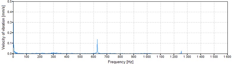
Fig. 12Vibration velocity spectrum of the microturbine casing at a speed of 44,940 rpm (749 Hz)
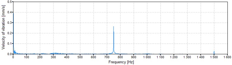
Fig. 13Vibration velocity spectrum of the microturbine casing at a speed of 55,920 rpm (932 Hz)
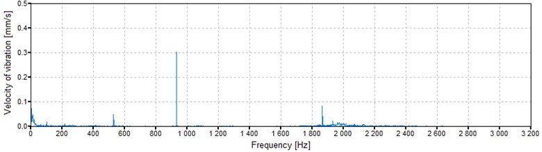
Table 1Vibrations of the microturbine casing depending on the rotational speed of the rotor
Rotational speed [rpm] | Frequency [Hz] | Synchronous (1) vibrations [mm/s] | Overall vibrations [mm/s] |
11,520 | 192 | 0.069 | 0.251 |
12,120 | 202 | 0.107 | 0.523 |
21,300 | 355 | 0.124 | 0.798 |
25,020 | 417 | 0.155 | 0.914 |
37,620 | 627 | 0.138 | 0.870 |
44,940 | 749 | 0.265 | 0.693 |
52,560 | 876 | 0.283 | 0.872 |
55,920 | 932 | 0.303 | 0.658 |
During the discussed tests of the microturbine, the sound intensity level was also measured. Unfortunately, due to the noise emitted by other devices situated in the laboratory, these measurements were made difficult. In general, it was found that the noise emitted by the operating microturbine was very low. At the nominal power of 1 kW, the sound intensity level registered at a distance of 2 m from the microturbine was 63 dB (Leq A). The shut-down of the microturbine did not decrease the sound intensity level. Therefore, it can be stated that the operation of the microturbine had no influence on the sound intensity level measured in the laboratory. The noise emitted by the microturbine itself was much lower than the measured noise.
5. Conclusions
The ever-increasing use of renewable energy sources and the development of distributed power engineering have increased demand for small cogeneration systems. With the development of such systems, the interest in machines that enable the generation of electricity from heat also increased. This article discusses numerical simulations and experimental research carried out on the prototypical fluid-flow machine, which allows for the small-scale production of electric energy. The nominal electric power of the developed microturbine is just 1 kW, which makes it possible to use it in single-family houses. In order to obtain such electric power, at quite low temperatures and flow rates of the working mediums that can be used in domestic cogeneration systems, it was necessary to employ the rotor capable to operate at a very high rotational speed, namely 120 krpm. Such high rotational speeds caused problems with the rotor dynamics and the bearings. Therefore, a decision was made to use unconventional gas bearings fed by the low-boiling medium’s vapour. In the following parts of the article, issues related to the design, numerical simulations and experimental research of the prototypical ORC microturbine are discussed.
The preliminary analysis covered various bearing systems, including rolling bearings, gas bearings and foil bearings. Due to the very high nominal rotational speed, and also due to the fact that there was no possibility to use a conventional lubricating medium, the gas bearings fed by the vapour of the working medium of the ORC system were picked. The bearings of this type allow for stable operation of the rotor at very high rotational speeds and do not require oil as a lubricating medium. Within the framework of further analyses, a selection of optimal dimensions of the bearings for specified operating conditions was made. Ultimately, it was decided to employ the bearings with a diameter of 24 mm and a length of 22 mm. The bearings with such dimensions had the required aerodynamic capacity at a speed greater than 8 krpm. At lower speeds, the bearings require an external supply system. The results of the further analysis were proof of very good dynamic properties of the rotor. The maximum vibration amplitude of the rotor did not exceed 2 µm for speeds up to 150 krpm. Moreover, the critical speed of the rotor was not in the analysed range of rotational speeds. It made it possible to design the whole microturbine followed by its manufacturing.
At a further stage of the research, the built machine was subjected to tests under laboratory conditions, during which target operating conditions were reproduced. To prevent unsealing of the machine, the vibration measurements were performed on its casing, using an accelerometer fixed in the vicinity of one of the gas bearings. The measurements were carried out in a broad frequency range, selected accordingly to the current rotational speed. It can be stated that the vibration level of the microturbine casing was very low in the whole range of rotational speeds. The highest vibration component was connected to the rotary motion of the rotor and occurred at the frequency which was equal to its rotational frequency (1). The vibration velocity of this component increased as the rotational speed of the rotor increased and the maximum value was approximately 0.3 mm/s. Besides the fundamental frequency (1), an increased vibration level was observed at very low frequencies (up to 50 Hz) as well as at a frequency two times higher than the rotational frequency of the rotor (2). However, this vibration was at a very low level. Also, the overall vibration level of the microturbine was very low. The measurements of the sound intensity level also showed that the tested machine has good dynamic performance. It turned out that the high sound intensity level in the laboratory (acoustic background) did not allow accurate measurements of the sound emitted by the microturbine alone. The measured noise level was at the same level regardless of whether or nor the microturbine operated.
It is worth emphasising that very good agreement between the computer simulation results and the experimental research results was obtained. On the basis of the calculation results, one can notice that the vibration level of the microturbine rotor increases as its rotational speed increases (up to a speed of about 60 krpm). The same tendency was observed with the measurements of relative vibration of the casing for speeds up to 56 krpm. This provides evidence that the used numerical models are highly reliable and can be used to anticipate the dynamic properties of energy microturbines prior to their manufacturing.
Within the framework of further research on the prototypical microturbine, a series of tests with various working mediums will be carried out under constant and variable operating conditions. It is also scheduled to test fast starts and stops of the machine, which during normal operation could be caused, for example, by sudden changes in demand for electrical energy. The research will be accompanied by vibration and noise measurements. The aim of the planned work is to develop the final version of the microturbine and implement it in small cogeneration systems.
References
-
Bronicki L. Y. Power Stations Using Locally Available Energy Sources. Encyclopedia of Sustainability Science and Technology Series. Springer, New York, 2018.
-
Mancarella P., Chicco G. Global and local emission impact assessment of distributed cogeneration systems with partial-load models. Applied Energy, Vol. 86, 2009, p. 2096-2106.
-
Schuwer D., Kruger C., Merten F., Nobel A. The potential of grid-orientated distributed cogeneration on the minutes reserve market and how changing the operating mode impacts on CO2 emissions. Energy, Vol. 110, 2016, p. 23-33.
-
Pethurajan V., Sivan S., Joy G. C. Issues, comparisons, turbine selections and applications – an overview in organic Rankine cycle. Energy Conversion and Management, Vol. 166, 2018, p. 474-488.
-
Andwari A. M., Pesyridis A., Efahanian V., Salvati Zadeh A., Hajialimohammadi A. Modelling and evaluation of waste heat recovery systems in the case of a heavy-duty diesel engine. Energies, Vol. 12, 2019, p. 1397.
-
Żywica G., Kaczmarczyk T. Z., Ihnatowicz E. A review of expanders for power generation in small-scale organic Rankine cycle systems: Performance and operational aspects. Proceedings of the Institution of Mechanical Engineers, Part A: Journal of Power and Energy, Vol. 230, 7, p. 669-684.
-
Kaczmarczyk T. Z., Ihnatowicz E., Żywica G., Kiciński J. Experimental investigation of the ORC system in cogenerative domestic power plant with a scroll expanders. Open Engineering, Vol. 5, 2015, p. 411-420.
-
Kolasiński P., Pomorski M., Błasiak P., Rak J. Use of rolling piston expanders for energy regeneration in natural gas pressure reduction stations – selected thermodynamic issues. Applied Sciences, Vol. 7, 2017, p. 535.
-
Rak J., Błasiak P., Kolasiński P. Influence of the applied working fluid and the arrangement of the steering edges on multi-vane expander performance in micro ORC system. Energies, Vol. 11, 2018, p. 892.
-
Klonowicz P., Witanowski Ł., Jędrzejewski Ł., Suchocki T., Lampart P. A turbine based domestic micro ORC system. Energy Procedia, Vol. 129, 2017, p. 923-930.
-
Klonowicz P., Borsukiewicz Gozdur A., Hanausek P., Kryłłowicz W., Bruggemann D. Design and performance measurements of an organic vapour turbine. Applied Thermal Engineering, Vol. 63, 2014, p. 297-303.
-
Weiß A. P., Popp T., Muller J., Hauer J., Bruggemann D., Preißinger M. Experimental characterization and comparison of an axial and a cantilever micro-turbine for small-scale organic rankine cycle. Applied Thermal Engineering, Vol. 140, 2018, p. 235-244.
-
Barse K. A., Mann M. D. Maximizing ORC performance with optimal match of working fluid with system design. Applied Thermal Engineering, Vol. 100, 2016, p. 11-19.
-
Pilavachi P. A. Mini- and micro-gas turbines for combined heat and power. Applied Thermal Engineering, Vol. 22, 2002, p. 2003-2014.
-
Hosseinalipour S. M., Abdolahi E., Rezaghi M. Static and dynamic mathematical modeling of a micro gas turbine. Journal of Mechanics, Vol. 29, Issue 2, 2013, p. 327-335.
-
Kiciński J., Żywica G. Steam Microturbines in Distributed Cogeneration. Springer, Cham, 2014.
-
Kolpakhchyan P. G., Parshukov V. I., Shaikhiev A. R., Kochin A. E., Podbereznaya M. S. High speed generator for gas microturbine installations. International Journal of Applied Engineering Research, Vol. 12, Issue 23, 2017, p. 13874-13878.
-
Włodarski W. Experimental investigations and simulations of the microturbine unit with permanent magnet generator. Energy, Vol. 158, 2018, p. 59-71.
-
Heshmat H., Walton II J. F., Hunsberger A. Oil-free 8 kW high-speed and high specific power turbogenerator. Proceedings of ASME TURBO EXPO, Dusseldorf, Germany, 2014.
-
Demierre J., Rubino A., Schiffmann J. Modelling and experimental investigation of an oil-free micro compressor-turbine unit for an ORC driven heat pump. Proceedings of ASME TURBO EXPO, Dusseldorf, Germany, 2014.
-
Żywica G., Bagiński P. Investigation of unconventional bearing systems for microturbines. Advances in Mechanism and Machine Science, Vol. 73, 2019, p. 3439-3448.
-
Tkacz E., Kozanecka D., Kozanecki Z., Łagodziński J. Oil-free bearing development for high-speed turbomachinery in distributed energy systems – dynamic and environmental evaluation. Open Engineering, Vol. 5, 2015, p. 343-348.
-
Larsen J. S., Hansen A. J., Santos I. F. Experimental and theoretical analysis of a rigid rotor supported by air foil bearings. Mechanic and Industry, Vol. 16, Issue 1, 2015, p. 106.
-
Ahmad W., Khan S. A., Islam M. M., Kim J.-M. A reliable technique for remaining useful life estimation of rolling element bearings using dynamic regression models. Reliability Engineering and System Safety, Vol. 184, 2019, p. 67-76.
-
Wu R. Q., Zhang W., Yao M. H. Nonlinear dynamics near resonances of a rotor-active magnetic bearings system with 16-pole legs and time varying stiffness. Mechanical Systems and Signal Processing, Vol. 100, 2018, p. 113-134.
-
Hu Z., Wang Z., Huang W., Wang X. Supporting and friction properties of magnetic fluids bearings. Tribology International, Vol. 130, 2019, p. 334-338.
-
Lin J.-W. Dynamic characteristics of magnetic fluid based sliding bearings. Mechanika, Vol. 19, Issue 5, 2013, p. 554-558.
-
Hernandez Carrillo I., Wood C., Liu H. Development of a 1000 W organic Rankine cycle micro-turbine-generator using polymeric structural materials and its performance test with compressed air. Energy Conversion and Management, Vol. 190, 2019, p. 105-120.
-
Kiciński J. Rotor Dynamics. IMP PAN Publisher, Gdansk, 2006.
-
Breńkacz L., Żywica G., Bogulicz M. Selection of the bearing system for a 1 kW ORC microturbine. Proceedings of the 10th International Conference on Rotor Dynamics – IFToMM 2018, Vol. 1, 2019, p. 223-235.
-
Schmied J., Fuchs A. Nonlinear analysis in rotordynamic engineering. Proceedings of the 10th International Conference on Rotor Dynamics – IFToMM 2018, Vol. 3, 2019, p. 426-442.
-
Walton II J.F., Heshmat H., Tomaszewski M. Power loss in high-speed micro turbomachinery – an experimental study. Proceedings of ASME TURBO EXPO, Copenhagen, Denmark, 2012.
-
Żywica G., Breńkacz Ł., Bogulicz M. Optimization of the bearing system for a micro-power turbogenerator with a rotational speed up to 120,000 rpm. Proceeding of the 13th International Conference on Dynamics of Rotating Machines, Copenhagen, Denmark, 2019.
About this article

This work has been founded by the Polish Agency for Enterprise Development and from the Smart Growth Operational Programme within project no. POIR.02.03.02-22-0009/15 (carried out jointly with the SARK Company) and scientific project No. 2016/21/D/ST8/01711, financed by the National Science Centre (NCN) in Poland.
Grzegorz Zywica managed research works and designed the microturbine, participated in numerical calculations and in experimental studies. Prepared the text of the manuscript and figures. Tomasz Kaczmarczyk prepared a research rig, participated in experimental research. Lukasz Brenkacz participated in numerical calculations of bearings and rotor dynamics. Malgorzata Bogulicz prepared the numerical model of the gas bearing and rotor, participated in the calculations. Artur Andrearczyk participated in the preparation of a microturbine prototype for tests, developed a measuring system. Pawel Baginski participated in the preparation of a microturbine prototype for tests and in vibration measurements.
