Abstract
Regenerative chatter can reduce machining quality, tool life, and productivity during milling process. In order to control the milling chatter, the stability analysis of milling system is very important. It has been found that variable spindle speed milling and the use of variable-angle tools are effective to control milling chatter. This paper mainly studies the control effect when these two methods are used simultaneously. Firstly, the improved full-discretization method is used to predict the stability of variable spindle speed milling process with variable pitch cutters. And on the basis of stability prediction, the influence of spindle speed modulation parameters on stability is analyzed. Meanwhile, the stability prediction results of down-milling and up-milling operations, different radial immersion ratio and different tooth pitch variation form are compared. The results show that the stability of variable spindle speed milling process with variable pitch cutters is better than that of variable pitch cutters in constant spindle speed milling process. And the improvement of the stability is related to the spindle speed modulation parameters. When the modulation parameters are bigger, the stable cutting area of the stability lobes diagram will be larger. Secondly, in the up-milling operation and the low immersion operation, the variable spindle milling with variable pitch cutters has better stability than the down milling operation and the high immersion operation. Under the condition that the pitch angles vary linearly, the stability is better. Finally, the time domain simulation is performed and the simulation results verify the accuracy of the stability prediction results.
1. Introduction
Milling chatter is a kind of self-excited vibration produced by the interaction between the tool spindle system and the workpiece during the milling process [1]. In order to obtain good quality of the surface, ensure machining accuracy and avoid tool damage, milling chatter must be prevented. In actual manufacturing practice, operators usually choose the cutting parameters conservatively to avoid the negative effects of chatter. However, the real machining performance of the machine tool will be reduced, and the manufacturing cost is increased. Therefore, the control of milling chatter and the prediction of its stability is crucial to achieve high performance and high efficiency machining.
Over the years, scholars all over the world have explored the method of controlling chatter from three aspects: spindle parameters, tool structure and variable spindle speed milling. And many achievements have been made.
The first kind of method is to reduce vibration or restrain vibration by setting additional control device on the machine tool. According to the control mode of the additional device, it can be divided into three types: active control, semi-active control and passive control. Ganguli et al. [2] investigated the effect of active damping on regenerative chatter instability. Munoa et al. [3] used the machine tool’s own drives to suppress chatter with the help of an external accelerometer located close to the tool center point. Duncan et al. [4] increased the damping of the spindle-cutter system near the chatter frequency by adding additional dampers to the spindle.
The second kind of method avoids the chatter by changing the tool structure, and the variable pitch cutter is widely used. The essence of suppressing chatter is to reduce the regenerative effect between the tool and the workpiece by changing the time delay in the control equation of the cutting process. Altintas et al. [5] applied the zeroth-order approximation (ZOA) to the prediction of the milling stability of variable pitch cutters. Budak [6, 7] proposed an analytical stability model and a design method for variable pitch cutters. Sellmeier and Denkena [8] investigated the process stability of variable pitch cutters experimentally and theoretically. Sims et al. [9] compared semi-discretization method (SDM), time-averaged semi-discretization method and time finite element analysis (TFEA). The results showed that all the three methods can achieve high accuracy in the prediction of the milling stability limit with variable pitch cutters. Niu et al. [10] extended Runge-Kutta (GRK) method to analyze the milling process stability with variable pitch cutters and cutter runout. Yang and Liu [11] studied the surface generation mechanism in peripheral milling with variable pitch cutters. Song et al. [12] proposed an approach to design variable pitch cutters with high milling stability. Olgac and Sipahi [13] proposed a mathematically novel and very recent paradigm, which named Cluster Treatment of Characteristic Roots, to determine analytically the bounds of the stable versus unstable chatter. Otto et al. [14] proposed a new method for the identification of the chatter stability lobes for variable pitch cutters from the linearized system that is based on the multifrequency solution. Jin et al. [15] presented an improved semi-discretization algorithm to predict the stability lobes for variable pitch cutters. Variable pitch milling cutters can improve the stability of milling better, but this method ignores the time-varying characteristics of milling forces, and it is passive control, so it is only suitable for large radial depth of cut milling stability prediction.
The third kind of methods changes the delay terms in the control equation of cutting process by periodically modulating the spindle speed so as to control chatter. Because it is not necessary to process the spindle and cutters and it is suitable for all kinds of machine tools, variable spindle speed milling has higher practical value. Zatarain [16] et al. used multi-frequency method to predict the stability limit of variable spindle speed milling. Xie [17, 18] et al. proposed an improved SDM for the prediction of the stability limit of variable spindle speed milling. Long and Balachandran [19] analyzed the variable spidle speed milling stability of the milling system with multiple degrees of freedom. Seguy [20] et al. analyzed the effect of spindle speed variation on machine tool chatter in high-speed milling. Totis [21] et al. proposed an innovative and fast algorithm based on the Chebyshev Collocation Method for chatter prediction in milling with variable spindle speed. Urbikain [22] et al. conducted a study of the real implementation of the variable spindle speed technique in turning systems. Gou [23] conducted some tests to investigate the effect of variable speed parameters and cutting conditions on suppressing the chatter in face milling. Variable spindle speed milling is an active control that can effectively suppress milling flutter at low speeds, but it cannot significantly control milling chatter at high speeds.
In the research process of stability prediction for milling chatter, many methods have been applied. Altintas and Budak [24] proposed single frequency approximation, Merdol and Altintas [25] proposed multi frequency method. Insperger and Stépán [26, 27] applied SDM for stability prediction. Mann and Patel [28] et al. used TFEA. Bobrenkov [29] et al. analyzed stability of milling chatter with the Chebyshev collocation method and the state-space TFEA technique.
Many scholars have carried out extensive research on the control of milling chatter and its stability prediction. However, these studies are limited to study the effects of changing a single parameter or structure on milling chatter, and the research to study the effects of combined methods on the suppression of chatter has not been found. Variable spindle speed and variable pitch cutters milling have been verified respectively for their suppression of chatter, but the range of application is very limited. Therefore, this paper aims to study the stability of milling chatter when these two methods of chatter control are adopted simultaneously. The structure of the paper is as follows. In Section 2, the mathematical model of variable spindle speed milling with variable pitch cutters is introduced. In Section 3, the transition matrix of the mathematical model of milling system is obtained by using an improved full-discretization method, and according to the Floquet theory, the criterion of stability is obtained. In Section 4, with the selected system parameters, the stability prediction is carried out and the stability lobes diagrams are drawn, the influence of spindle modulation parameters on stability is analyzed, and the stability prediction results under different working conditions are compared. Time domain simulations are carried out to verify the results in Section 5. Conclusions are presented in Section 6.
2. Mathematical model of variable spindle speed milling with variable pitch cutters
The milling physical model used in this paper is a two degrees of freedom system. The model of a workpiece-tool system is shown in Fig. 1.
Fig. 1Physical model of workpiece-tool system with two degrees of freedom
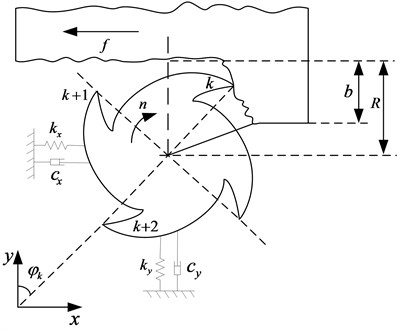
In Fig. 1 is feed rate, is spindle speed, and the direction is as shown, is the radial cutting depth. The flexible cutter is simplified as a spring-mass-damping system with two degrees of freedom and . The mathematical model [30] of the workpiece-tool system with two degrees of freedom has the following form:
where , , , represent mass matrix, damping matrix and stiffness matrix, respectively.
The cutting force of the variable pitch helical cutter can be written as follows:
where is a window function with the following form:
and are the angles when the teeth enter and leave the workpiece. And is a dynamic stiffness matrix:
where:
, , and in Eq. (5) can be expressed as:
In Eq. (9) and are:
The radius of cutting tool is , and is a helix angle, is the number of flutes and is the normal rake angle. is the specific cutting energy, is a proportionality factor, is the friction coefficient for sliding between the chip and the rake face of the cutting tooth.
In this paper, the chatter suppression effect of a sinusoidal modulation spindle speed is studied. The spindle speed varies in form as:
where is the nominal spindle speed, the unit is rps. is the modulation amplitude ratio, in practice, should be less than 0.2 [31]. is the frequency of spindle speed variation. The period of spindle speed variation is , is modulation frequency ratio. When the spindle speed varies as Eq. (12), the angular position of the th tooth with axial coordinate at moment is:
where tooth spacing angle is:
where represents the angle between the th teeth and the 1th teeth. The time delay in variable speed milling process with variable pitch cutter can only be given in the implicit form:
where:
where represents the angle between the 1th teeth and the th teeth, represents the angle between the th teeth and the first teeth. Substituting Eq. (12) into Eq. (15) results in the following relationship:
For small and small , can be approximated as:
where the nominal delay is:
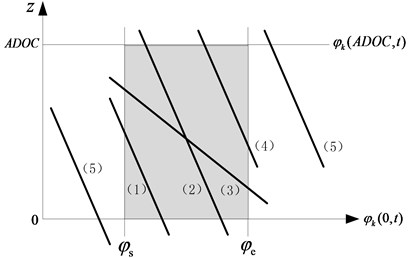
To determine the cutting force, we should know the lower limits and upper limits of the integration in Eq. (6)-(8). When the effect of helix angle is considered [18], the determination of the lower and upper limits of the integration can be divided into five cases:
1) If and then ;
2) If and then ;
3) If and , then , ;
4) If and then ;
5) If and , or and , there is no cutting force on the tooth flute, the lower and upper limits of the integration are both 0.
3. Stability limit prediction model based on improved full-discretization method
Since the chatter stability of the milling system is independent of the feed motion, so feed motion item in Eq. (1) can be omitted. Let and , Eq. (1) can be represented by:
with:
Obviously, coefficient matrix , and time delay are periodic at the least common multiple of the spindle modulation period and the nominal rotation period of the spindle , namely:
when , are rational number and relative primes, the milling system is periodic at the principal period , the Floquet theory of periodic DDEs can be applied [32].
Fig. 2The lower and upper limits of the integration of cutting force
The first step of improved full-discretization is the construction of the time interval. Divide the principal period of the system into intervals with length . The time-step can be expressed as:
The average delay for the discretization interval is defined as:
where:
The series of integers is introduced as follows:
where int(*) is the function that rounds positive numbers towards zero. Since the time delay is varying periodically with time, integer may be different for different discretization steps. The maximum value of is introduced as:
Note that can be considered as an approximation parameter regarding the length of the time delay.
Solving Eq. (20) as an ordinary differential equation over the discretization interval with initial condition , the following equation is derived:
when , the system (30) leads to:
Using the improved full-discretization method to discretize all the items in Eq. (31), the time delay term is discretized as:
with:
The state term can be approximated as:
The coefficient matrix , can be approximated as follows:
Substituting Eq. (32)-(37) into Eq. (31), we obtain:
where coefficient matrix , , , can be expressed as:
In Eq. (40)-(42), , and can be expressed as follows:
where denotes the identity matrix. Considering that the system state depends only on , and , and nothing to do with . And the maximum value of is . A new state vector is introduced as follows:
Using the state vector (46), Eq. (38) can be written as:
with:
where , , , . is determined by the number of cutter teeth that are actually involved in cutting at each moment. The location of and in the matrix is determined by . is the number of cutter teeth when the maximum value of is taken.
According to Eq. (47), in the principal period , we can obtain that:
The approximate Floquet transition matrix is obtained as:
According to the Floquet theory [33], the stability of the system can be determined by using the following criterions. If the moduli of all the eigenvalues of the transition matrix are within the unit circle, the system is stable. If one or more eigenvalues are on the unit circle and the remaining eigenvalues are inside the unit circle, the system will undergo a bifurcation. Otherwise, the system will be unstable.
4. Stability prediction results and parameter influence analysis
Based on the model proposed above, the stability limit is predicted. When calculating and drawing the stability lobes diagrams, the axial depth of cut and nominal spindle speed are chosen as the control parameters. The variable pitch cutter with varying pitch angles of 60°-120°-60°-120° is used in the stability limit prediction. The spindle speed modulation parameters of variable speed milling are indicated in each drawing. Other parameters as shown in Table 1 and Table 2 are selected from the Altintas’s paper [5].
Table 1Parameters of the workpiece-tool system
Direction | Mass (kg) | Stiffness (N/m) | Natural frequency (Hz) | Damping ratio |
1.4986 | 1.879×10⁷ | 563.6 | 0.055801 | |
1.1990 | 1.261×10⁷ | 516.21 | 0.025004 |
Table 2Structural parameters of cutter and cutting parameters
Rake angle | Helix angle | Tool diameter (mm) | Specific cutting energy (Pa) | Proportionality factor (Pa) | Friction coefficient |
15° | 30° | 9.525 | 6.79×10⁸ | 0.367 | 0.2 |
First, the effect of variable pitch milling and variable spindle speed milling for chatter suppression are investigated respectively. Under the condition of 50 % immersion down-milling operations, the stability lobes diagrams of constant spindle speed milling with constant pitch cutter (CSCP), constant spindle speed milling with variable pitch cutter (CSVP) and variable spindle speed milling with constant pitch cutter (VSCP) are plotted in Fig. 3, respectively. The spindle speed modulation parameters used in variable speed milling are 0.1 and 0.5. As can be seen from the Fig. 3, both variable pitch milling and variable speed milling can improve the stability of CSCP to some extent. The similarity between the two methods of chatter control is that the improvement effect is shown as the promotion of the valley of the stability lobes. At the same time, both of them will cause a decrease in the crest at certain spindle speeds. The difference is that compared with the constant pitch cutter, the position of the lobes changed greatly for variable pitch cutter. However, compared with constant spindle speed milling, variable spindle speed milling leaves little change in the position of the lobes.
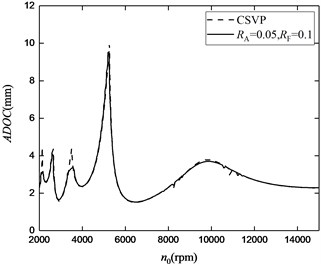
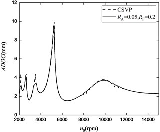
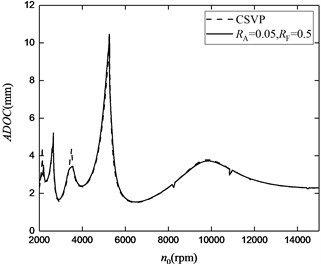
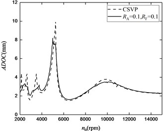
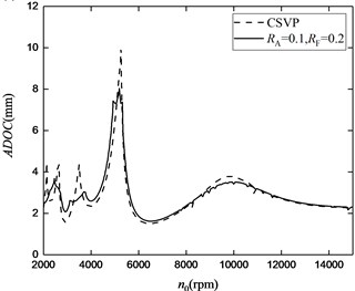
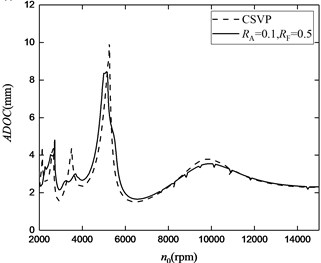
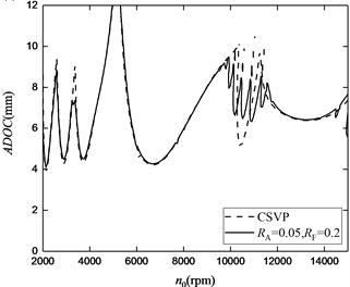
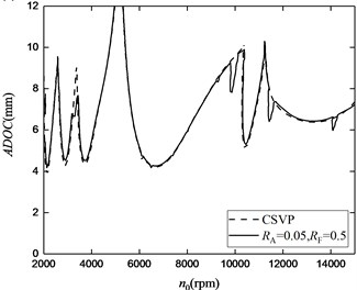
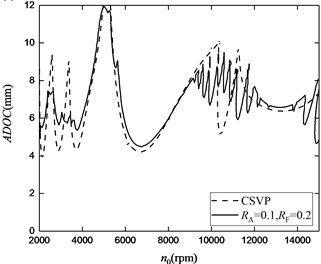
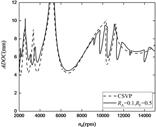
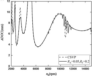
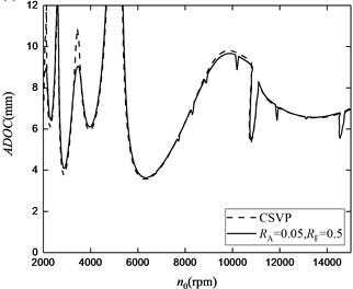
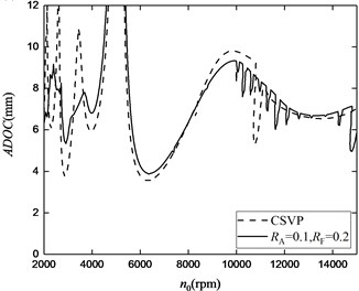
In order to investigate the effect of variable spindle speed milling process with variable pitch cutter (VSVP) on chatter suppression, under the condition of 50 % immersion down-milling operations, the stability lobes diagrams of CSVP and VSVP are plotted in Fig. 4. The dot line and solid line represent CSVP and VSVP, respectively.
Fig. 3The stability lobes for variable pitch milling and variable spindle speed milling
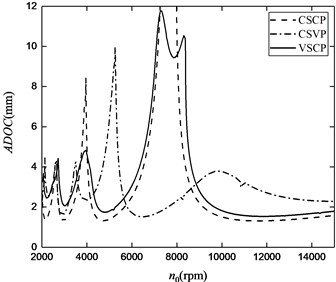
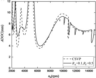
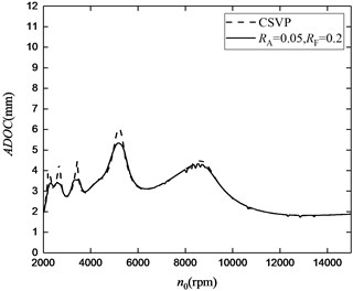
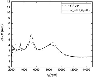
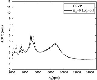
Fig. 4The stability lobes for different modulation parameters. a) RA= 0.05, RF= 0.1, b) RA= 0.05, RF= 0.2, c) RA= 0.05, RF= 0.5, d) RA= 0.1, RF= 0.1, e) RA= 0.1, RF= 0.2, f) RA= 0.1, RF= 0.5
a)
b)
c)
d)
e)
f)
From Fig. 4, it is easy to find that VSVP milling has a larger stable cutting area than CSVP, which means that the stability is improved. But for different modulation amplitude ratio , the improvement effect of stability is different. When 0.05, the stability lobes of VSVP are almost coincided with those of CSVP, implying that the chatter suppression effect is not obvious. However, when 0.1, the stable cutting area for stability lobes of VSVP is obviously larger than that of CSVP. And the extent of expansion of the stable cutting area is more obvious in the low spindle speed zone. The cause of this phenomenon is that the variation of spindle speed disrupts the cutting internal mechanism to some extent, resulting in stability region change [32]. And when the spindle speed variation is obvious, the change of stable cutting area is more obvious. Although a larger value can obtain a larger stable region, the modulation amplitude ratio needs to be controlled within a certain range to avoid the possible adverse effects of excessive instantaneous spindle speed. In addition, the stability lobes for CSVP and VSVP are also different at different modulation frequency ratio . With the same , the stable cutting area expands with the increase of . As we know, determines the period of spindle speed variation . When is larger, will be smaller. Therefore, when the variation of spindle speed is intense, the stable cutting area is larger. However, whether the excessive can produce adverse effects needs to be further studied and it will be studied in the later research.
Fig. 5The stability lobes for up-milling operations: a) RA= 0.05, RF= 0.2, b) RA= 0.05, RF= 0.5, c) RA=0 .1, RF= 0.2, d) RA= 0.1, RF= 0.5
a)
b)
c)
d)
Next, the chatter suppression effect of VSVP is investigated under up-milling operations. Keep other parameters constant, under the condition of 50 % immersion up-milling operations, the stability lobes diagrams of CSVP and VSVP are plotted in Fig. 5. In up-milling operations, the chatter suppression effect for VSVP relative to CSVP is similar with that in down-milling operations. The improvement effect is shown as the promotion of the valley of the stability lobes, and the extent of promotion is related to spindle speed modulation parameters. Compared with the simulation results under the corresponding modulation parameters in Fig. 4, we can also find that the overall height of lobes in up-milling operations is higher than down-milling operations. Therefore, the up-milling operations have better stability.
Next, the chatter suppression effect of VSVP with low immersion ratio is investigated. Under the condition of 10 % immersion down-milling operations, the stability lobes diagrams of CSVP and VSVP are plotted in Fig. 6. Under the condition of low-immersion operations, the chatter suppression effect for VSVP relative to CSVP is similar with that under the condition of high-immersion operations. The improvement effect is also shown as the promotion of the valley of the stability lobes, and the extent of promotion is related to spindle speed modulation parameters. Meanwhile, under the condition that the speed is constant, we can also find that the overall height of lobes in low-immersion operations is higher than high-immersion operations, which is shown in Fig. 4. Therefore, the low-immersion operations have better stability.
Fig. 6The stability lobes for low-immersion operations: a) RA= 0.05, RF= 0.2, b) RA= 0.05, RF= 0.5, c) RA= 0.1, RF= 0.2, d) RA= 0.1, RF= 0.5
a)
b)
c)
d)
Finally, the chatter suppression effect of VSVP with different tooth pitch variation form is investigated. The above analysis is all carried out under the condition that the pitch angles of each cutters are 60°-120°-60°-120°, which is alternate change case. For linear change case, when the pitch angles of each cutters are 60°-80°-100°-120°, under the condition of 50 % immersion down-milling operations, the stability lobes diagrams of CSVP and VSVP are plotted in Fig. 7, respectively. When the pitch angles vary linearly, the chatter suppression effect for VSVP relative to CSVP is similar with that in pitch alternate change case. The improvement effect is also shown as the promotion of the valley of the stability lobes, and the extent of promotion is related to spindle speed modulation parameters. In addition, under the condition that the pitch angles vary linearly, we can find that the overall height of lobes is higher than pitch alternate change case, which is shown in Fig. 4. But at some wave crests, the stability limit is smaller in pitch alternate change case.
Fig. 7The stability lobes for different tooth pitch variation form: a) RA= 0.05, RF= 0.2, b) RA= 0.05, RF= 0.5, c) RA= 0.1, RF= 0.2, d) RA= 0.1, RF= 0.5
a)

b)
c)
d)
5. Time domain simulation verification
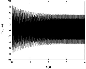
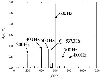
In order to verify the accuracy of stability prediction results, the cutting state of fixed working points is simulated by Simulink. Use the parameters in Tables 1 and 2, under the condition of 50 % immersion down-milling operations, and the pitch angles are 60°-120°-60°-120°, 0.1, 0.5, the stability lobes diagrams of VSVP are plotted in Fig. 8. Three working points are selected in Fig. 8 named A ( 3000, 3), B ( 5000, 4) and C ( 12000, 2), respectively. Under the same system parameters and working conditions, time domain displacement curves of A, B and C are obtained by Simulink, and then the frequency spectrums of these three points are also obtained. Displacement curves and frequency spectrums are plotted in Fig. 9.
Fig. 8Stable lobes diagram and selected simulation points
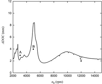
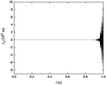
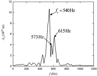
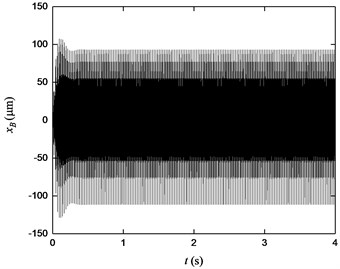
According to these displacement curves, the displacement of point A presents the state of dispersing, while the displacements of B and C are stable in steady state. Meanwhile, according to the frequency spectrums, the chatter frequency dominates in the frequency spectrum of point A. For point B and C, the spindle rotation frequency and its frequency multiplications dominant in the frequency spectrums. Therefore, the cutting state of A is unstable, and B and C are in steady state of cutting. Since point A is selected from the unstable cutting area, and point B and C are selected from the stable cutting area, the stability prediction results are agreement with the simulation results which means the results are verified in time domain.
Fig. 9Time domain displacement curves and frequency spectrums of each working point: a) displacement of A, b) frequency spectrum of A, c) displacement of B, d) frequency spectrum of B, e) displacement of C, f) frequency spectrum of C

a)
b)
c)
d)
e)
f)
6. Conclusions
In this paper, the improved full-discretization method is used to predict the stability of variable spindle speed milling process with variable pitch cutters. The main results of the present work are summarized as follows:
1) When the variable speed milling and variable pitch cutters are adopted simultaneously, the stability of milling system can be improved, and the chatter control effects of the combined method are better than the single method.
2) When the values of modulation amplitude ratio and modulation frequency ratio are bigger, the stable cutting area of stability lobes diagram will be larger, and the stability will be improved.
3) In up-milling operations and low-immersion operations, the stability of variable spindle speed milling process with variable pitch cutters is better than down-milling operations and high-immersion operations.
4) Under the condition that the pitch angles vary linearly, the stability of variable spindle speed milling process with variable pitch cutters is better than that of pitch alternate change case.
5) According to the simulation results in time domain by Simulink, the stability prediction results are verified.
References
-
Tobias S. A., Fishwich W. Theory of regenerative machine tool chatter. Engineer, Vol. 205, 1958, p. 199-203.
-
Ganguli A., Deraemaeker A., Preumont A. Regenerative chatter reduction by active damping control. Journal of Sound and Vibration, Vol. 300, Issue 3, 2007, p. 847-862.
-
Munoa J., Beudaert X., Erkorkmaz K., Iglesias A., Barrios A., Zatarain M. Active suppression of structural chatter vibrations using machine drives and accelerometers. CIRP Annals-Manufacturing Technology, Vol. 64, Issue 1, 2015, p. 385-388.
-
Duncan G. S., Tummond M. F., Schmitz T. L. An investigation of the dynamic absorber effect in high-speed machining. International Journal of Machine Tools and Manufacture, Vol. 45, Issue 4, 2005, p. 497-507.
-
Altintas Y., Engin S., Budak E. Analytical stability prediction and design of variable pitch cutters. Journal of Manufacturing Science and Engineering, Vol. 121, Issue 2, 1999, p. 173-178.
-
Budak E. An analytical design method for milling cutters with nonconstant pitch to increase stability, Part I: theory. Journal of Manufacturing Science and Engineering, Vol. 125, Issue 1, 2003, p. 29-34.
-
Budak E. An analytical design method for milling cutters with nonconstant pitch to increase stability, Part II: application. Journal of Manufacturing Science and Engineering, Vol. 125, Issue 1, 2003, p. 35-38.
-
Sellmeier V., Denkena B. Stable islands in the stability chart of milling processes due to unequal tooth pitch. International Journal of Machine Tools and Manufacture, Vol. 51, Issue 2, 2011, p. 152-164.
-
Sims N. D., Mann B., Huyanan S. Analytical prediction of chatter stability for variable pitch and variable helix milling tools. Journal of Sound and Vibration, Vol. 317, Issue 3, 2008, p. 664-686.
-
Niu J. B., Ding Y., Zhu L. M., Ding H. Mechanics and multi-regenerative stability of variable pitch and variable helix milling tools considering runout. International Journal of Machine Tools and Manufacture, Vol. 123, 2017, p. 129-145.
-
Yang D., Liu Z. Q. Surface plastic deformation and surface topography prediction in peripheral milling with variable pitch end mill. International Journal of Machine Tools and Manufacture, Vol. 91, 2015, p. 43-53.
-
Song Q. H., Ai X., Zhao J. Design for variable pitch end mills with high milling stability. International Journal of Advanced Manufacturing Technology, Vol. 55, Issues 9-12, 2011, p. 891-903.
-
Olgac N., Sipahi R. Dynamics and stability of variable-pitch milling. Journal of Vibration and Control, Vol. 13, Issue 7, 2007, p. 1031-1043.
-
Otto A., Rauh S., Ihlenfeldt S., Radons G. Stability of milling with non-uniform pitch and variable helix tools. International Journal of Advanced Manufacturing Technology, Vol. 89, Issues 9-12, 2017, p. 2613-2625.
-
Jin G., Zhang Q. C., Hao S. Y., Xie Q. Z. Stability prediction of milling process with variable pitch cutter. Journal of Mechanical Engineering Science, Vol. 228, Issue 2, 2013, p. 281-293.
-
Zararain M., Bediaga I., Munoa J., Lizarralde R. Stability of milling processes with continuous spindle speed variation: analysis in the frequency and time domains, and experimental correlation. CIRP Annals – Manufacturing Technology, Vol. 57, Issue 1, 2008, p. 379-384.
-
Xie Q. Z., Zhang Q. C. Stability predictions of milling with variable spindle speed using an improved semi-discretization method. Mathematics and Computers in Simulation, Vol. 85, Issue 3, 2012, p. 78-89.
-
Xie Q. Z., Zhang Q. C., Wang W., Jin G., Han J. X. Stability analysis for variable spindle speed milling with helix angle using an improved semi-discretization method. Science China Technological Sciences, Vol. 56, Issue 3, 2013, p. 648-655.
-
Long X. H., Balachandran B. Stability of up-milling and down-milling operations with variable spindle speed. Journal of Vibration and Control, Vol. 16, Issue 16, 2010, p. 1151-1168.
-
Seguy S., Dessein G., Arnaud L., Insperger T. Control of chatter by spindle speed variation in high-speed milling. Advanced Materials Research, Vol. 112, Issue 1, 2010, p. 179-186.
-
Totis G., Albertelli P., Sortino M., Monno M. Efficient evaluation of process stability in milling with spindle speed variation by using the Chebyshev collocation method. Journal of Sound and Vibration. Vol. 333, Issue 3, 2014, p. 646-668.
-
Urbikain G., Olvera D., López De Lacalle L. N., Elías Zúñiga A. Spindle speed variation technique in turning operations: modeling and real implementation. Journal of Sound and Vibration, Vol. 383, 2016, p. 384-396.
-
Gou Z. J. The trial research on suppressing the chatter by variable speed milling. Advanced Materials Research, Vol. 291, Issue 294, 2011, p. 2010-2013.
-
Altintas Y., Budak E. Analytical prediction of stability lobes in milling. CIRP, Vol. 44, Issue 1, 1995, p. 357-362.
-
Merdol S. D., Altintas Y. Multi frequency solution of chatter stability for low immersion milling. Journal of Manufacturing Science and Engineering, Vol. 126, Issue 3, 2004, p. 459-466.
-
Insperger T., Stépán G. Semi-discretization method for delayed systems. International Journal for Numerical Methods in Engineering, Vol. 55, Issue 5, 2002, p. 503-518.
-
Insperger T., Stépán G. Updated semi-discretization method for periodic delay-differential equations with discrete delay. IEEE Conference on Decision and Control, Vol. 3, Issue 3, 2004, p. 117-141.
-
Mann B. P., Patel B. R. Stability of delay equations written as state space models. Journal of Vibration and Control, Vol. 16, Issues 7-8, 2010, p. 1067-1085.
-
Bobrenkov O. A., Khasawneh F. A., Butcher E. A., Mann B. P. Analysis of milling dynamics for simultaneously engaged cutting teeth. Journal of Sound and Vibration, Vol. 329, Issue 5, 2010, p. 585-606.
-
Balachandran B., Zhao M. X. A mechanics based model for study of dynamics of milling operations. Meccanica, Vol. 35, Issue 2, 2000, p. 89-109.
-
Insperger T., Stépán G. Stability analysis of turning with periodic spindle speed modulation via semidiscretization. Journal of Sound and Vibration, Vol. 10, 2004, p. 1835-1855.
-
Seguy S., Insperger T., Arnaud L., Dessein G., Peigné G. On the stability of high-speed milling with spindle speed variation. International Journal of Advanced Manufacturing Technology, Vol. 48, Issues 9-12, 2010, p. 883-895.
-
Hahn W. On difference-differential equations with periodic coefficients. Journal of Mathematical Analysis and Applications, Vol. 3, Issue 1, 1961, p. 70-101.
About this article

We would like to express the appreciation to the National Science Foundation of China (Grant No. 51675901), Collaborative Innovation Center of Major Machine Manufacturing in Liaoning.
