Abstract
High-speed milling of thin-walled part is a common application for aerospace industry, automotive, computer hardware and bioengineering industries. Aiming at the small-stiffness frequency response characteristics of thin-walled parts, the dynamic model and critical condition of stability was proposed by the relative transfer functions between cutter subsystem and thin-walled part subsystem in this paper. The stability critical domain was predicted by semi-discretization (SD) method based on the dynamic behavior of the multi-DOF system. It can be shown that the chatter condition in high-speed milling is closely related to both cutter speed and depth of cut, besides cutter geometry, engagement conditions, relative frequency response function, material property of thin-walled part and so on. This conclusion provides a theoretical foundation and reference for the milling mechanism research.
1. Introduction
Nowadays peripheral milling machining is one of the most important manufacturing processes, and the technology of this process has been widely developed in recent years. However, productivity is often limited by strong vibrations; this regenerative vibration creates chatter. Chatter causes poor surface roughness, increases the rate of tool wear and reduces the spindle life span. Machining of thin-walled parts requires large amount of material removal, hence affecting the overall production time and cost. The problems that emerge due to high flexibility of the cutting tool-workpiece system limits the productivity, especially when trial and error based approaches are employed to set cutting conditions [1, 2]. The relative vibrations between flexible end mill and workpiece are the source of most of the problems that occur during manufacturing of thin webs. Intermittent engagement of cutter and workpiece excites a wide range of structural natural frequencies that result as unstable chatter vibrations and stable forced vibrations [3-5].
Some researchers have studied on the chatter stability in general milling for several years. Altintas [6, 7] presented chatter stability in the different milling conditions. Pogacink [8] investigated on dynamic stability by the method of parameters optimization. Thevenot [9] proposed the dynamic behavior variations in the 3D lobe diagram based on thin-walled workpiece, which the model was verified by milling test. Budak [10-14] presented chatter stability by the variable pitch cutters based on the flexible components and predicted workpiece dynamics in milling process based on the updated finite element model. Song [15] studied the predicting simultaneous dynamic stability limit of thin-walled part in high-speed milling process by finite element method. Tang [16] and Bravo [17] investigated the milling stability of thin-walled component and extended to 3D stability analysis, which cutting parameters were optimized based on the appropriate dynamic behavior. Insperger [19] predicted the chatter stability by the semi-discretization method for periodic delay-differential equations.
This paper is divided into four main sections; in the first part, entitling the proposed model, a dynamic model between flexible cutter and workpiece will be proposed. In the second section, the relative transfer function of cutter-workpiece system will be applied by discussing transfer functions of thin-walled part and cutter respectively, and then the modal test will be conducted. The third part, the calculation model of stability lobes and simulation process, will built machining stability model based on the relative transfer function, the simulation flow process and so on. The next part, the influence analysis of technological parameters on chatter stability, will analyze chatter stability relative to both cutter speed and depth of cut, besides cutter geometry, engagement conditions, and frequency response function. Finally, in section four section, some conclusions and suggestions from this study are given.
2. The proposed model
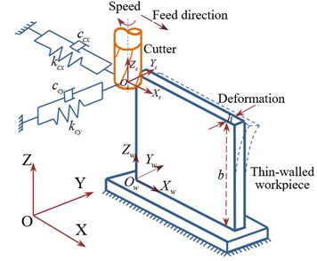
The final dimensional accuracy of the finished surface is one of the significant objectives of thin-walled machining. The static deflections caused by the forces, and relative vibrations between cutting tool and workpiece may result in surface location errors (SLE), as shown in Fig. 1(a). The surface accuracy for milling of thin walled components has to be investigated considering the relative static deflections between flexible tool and flexible workpiece. Furthermore, the machining system (tool subsystem and thin-walled subsystem) is flexible in the perpendicular direction to the cutting speed, which the vibration will increase in the case of the gap between a pass and the previous one causes an increase in the width of the chip in Fig. 1(b).
When the tool and thin-walled part have similar dynamic behaviors, the two subsystems have simultaneous displacement produced by the cutting forces. These displacements are intimately related, as both subsystems are in contact with each other with the tool teeth action. The cutting force appears out along this contact between tool and thin-walled part, which will effect on dynamics of milling system, so the method is presented here in multi-modes.
Fig. 1Scheme of the “flexible cutter-workpiece” system
a)
b)
2.1. Relative transfer function of tool-workpiece system model
Machine tools have multiple degrees of freedom (DOF) in various directions. The vibrations between the cutting tool and generated workpiece surface are the main interest. From the Newton’s second law, the equation of motion for the cutting tool or workpiece can be written in matrix form yields as:
Because the modes are orthogonal to each other, they have the following properties:
where is the modal mass associated with the first mode. When the orthogonality pinciple is applied aimilaily to the remaining mode shapes, the local mass and stiffness mateixes are the transformed into modal coordinates:
The resulting modal mass ([]) and modal stiffness ([]) matrixes are diagonal, and each diagonal element represents the modal mass or modal stiffness associated with a mode. The transformed modal damping matrix [] is also disgnal.
By applying modal transformations to Eq. (1), we can obtain the equations of motion in modal coordinates:
By applying the same modal transformations to both sides of the equations of motion for forced vibrations Eq. (1) the force vector can be transformed to modal coordinates:
The forced vibration expressions in modal coordinates become:
The modal displacements can be expressed as matrix form:
where is the diagnal modal transfer function matrix. Substitutiong and into Eq. (7), we obtain the vibrations in local coordinates:
or:
where is the eigenvector for mode k, and n is the number of degrees of freedom. Thus the harmonically forced vibrations for each coordinate can be calculated using the mode shaps , mode transfer functions , and the external force vector .
The frequency response function is expressed for workpiece – tool system in one degree of freedom:
where is stiffness (N/mm2), is damp ratio, is frequency (Hz)
The frequency response function is expressed for tool subsystem in multi-degrees of freedom as follows:
Similarly, the workpiece subsystem frequency response function is given:
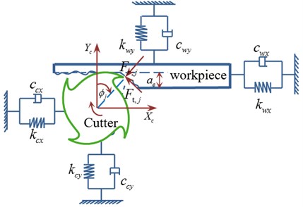
The relative displacement between the tool and workpiece is (), where and are displacements of the tool and workpiece, respectively. The cutting forces acting on the tool () and the workpiece () have the same opposing directions (i.e., ). The displacement and force vectors for an -DOF system can be expressed in local coordinates as:
The equation of motion for the system is:
where the local mass [], damping [], and stiffness [] matrices are square with dimentions [], and the force vector has a dimension of []. The solution of the eigenvalue problem leads to a modal matrix [] with a dimention of []:
or:
where each column represents a mode shape of the n-DOF system structure. From the modal coordinate transformation equation (), the and the workpiece displacements can be calculated using the associated rows t and w of the above modal matrix:
Substituting the modal force into the modal displacement vector , and remembering that all elements of the force vector {} are zero except the two corresponding to coordinates and , yields:
Substitution of these modal displacements into Eq. (17) gives the local displacements of the tool and workpiece, respectively:
When the machine tool structure is excited by a harmonically varying force at the cutting point, the relative transfer function between the tool and workpiece becomes:
2.2. The calculation model of chatter stability
After the development of this relative transfer function, the calculation model of the stability lobe diagram analytically is the next step. The resulting chip thickness consists of the static part , attributed to rigid body motion of the cutter, and a dynamic component caused by the vibrations of the tool at the present and previous tooth periods. Since the chip thickness is measured in the radial direction, the general dynamic chip thickness can be expressed as follows:
where, is feed rate per tooth, is the dynamic displacement vector of tool at the present time . is displacement vector of workpiece at the present time . is the instantaneous angular immersion of tooth as following:
where, is number of cutter, is rotational speed.
The function is a unit step function that determines whether the tooth is in or out of cut, that is:
where, and are that start and exit immersion angles of the cutter to and from the cut, respectively.
The governing equation of milling is a delayed differential equation with the tooth-passing period as delay. The dynamic equation of “cutter-workpiece” is expressed as follows:
where, , .
Using to the Eq. (12), which may be rewritten as [19]:
Discretization is introduced using a time interval with . The delayed state is approximated by:
The solution of milling dynamic equation is expressed as follows:
There are two possible instabilities can be observed: the critical eigenvalue is greater than 1. This case corresponds to the Hopf bifurcation causing the quasiperiodic chatter. The critical eigenvalue is real and its value is smaller than –1. This case corresponds to the period doubling or flip bifurcation, which causes the periodic chatter.
3. Modal test and milling forces
3.1. Modal tests of both cutter and workpiece
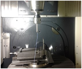
The difference between the transfer function of the relative movement with respect to the treatment of the tool’s and workpiece’s transfer functions as two independent entities seems obvious. For the transfer function of tool and workpiece, the modal test is conducted in 5-axis machining center (DMU50). The diameter of cutter is 16 mm. There are some equipment as follows: 1) modal testing and analysis software Cut/Pro; 2). USB Carrier I/O-9233; Accelerometer sensor8778a500 (Sensitivity 10.00 mV/g); Hammer type (B&K8206-002) 9722a500 (Sensitivity 10.00 mV/g); Sampling Rate (Hz):50000; Frequency Range (Hz): 50-5000; Transfer functions: Displacement-Force.
Fig. 2The modal test of cutter and thin-wall part
a) Accelerometer sensor on cutter tip
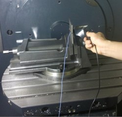
b) Modal tests of thin-wall part
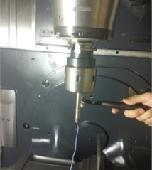
c) Modal tests of cutter
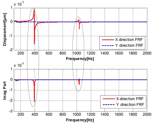
The frequency response functions (real part and imagine part) of tool point are measured in and direction, as shown in Fig. 3. The modal parameters are identified based the transfer function, as shown in Table 1. The frequency response functions (real part and imagine part) of thin-walled part are measured in and direction, as shown in Fig. 4. The multi-modes relative transfer function of tool and workpiece are shown in Fig. 5. It can be shown that the transfer function of the structure of a processing system depends on the relative relationship between the two subsystems. A first-order natural frequency equal to the natural frequency between the lowest among all the natural frequency, the last-order natural frequency is equal to the natural frequency between the highest natural frequency, that is the natural frequency of the system is relatively low to the high order by sequentially increased number order.
Fig. 3Two orthogonal direction FRFs measured at the tool tip
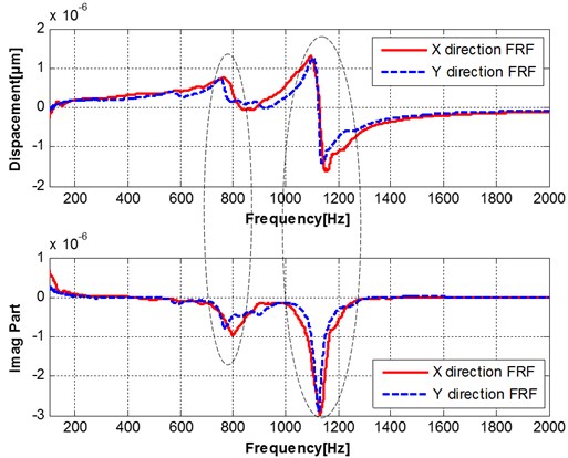
Fig. 4Two orthogonal direction FRFs measured at thin-walled part
The frequency response function (FRF) matrix of the machine-tool structure at the tool tip (tip-tip FRFs) was determined by an impact test procedure. In order to check for the presence of mode coupling, the tool response was measured in and directions at both locations. The measured FRFs were curve fit by commercial modal analysis software to identify the modal parameters and calculate the tip-tip FRFs. The obtained diagonal elements of the system for the tip-tip FRFs are listed in Table 1.
Table 1The modal parameters of milling cutter
Modal parameter | direction | direction | ||||
Natural frequency (Hz) | Damping ratio | Rigidity (N/m) | Natural frequency (Hz) | Damping ratio | Rigidity (N/m) | |
First order of cutter | 802 | 0.0549 | 7.9541e6 | 769 | 0.1021 | 4.1326e6 |
Second order of cutter | 1140 | 0.0263 | 4.678e6 | 1124 | 0.0156 | 7.1136e6 |
Fig. 5Relative transfer function of multi-modes in x direction
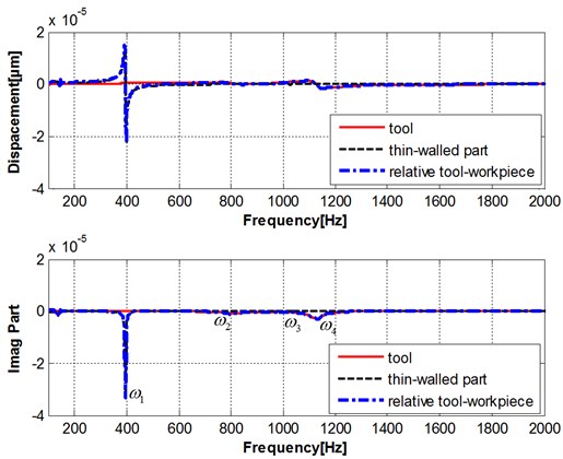
According to the analyzed first order and second order frequency for cutters and workpieces and the relative transfer function theory, the transfer function of the structure of the processing system depends on the relative relationship between the tool and workpiece subsystem. The first order frequency equals the lower natural frequency of tools and workpieces; the second order frequency equals the higher natural frequency of tools and workpieces.
3.2. Measurement of milling force coefficient
3.2.1. Experiment setup
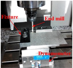
The milling tests were a CNC vertical machining center VMG850, equipped with variable spindle speed from 100 to 8000 rpm. A three-dimensional Kislter9265B dynamometer was mount on machine table to measure the cutting forces, and the instantaneous cutting force were recorded in , and direction by a type Dyno Ware signal analyzer software after amplification using a type 5070A multi-channel charge amplifier. The workpiece was mounted on the dynamometer through a specially designed fixture. The cutting tool (one insert used) in the experiment was a 12-mm diameter end mill (catalog number: EGO EAP300R 12D120L GC-0109) with a tool holder. The insert is APMT 1135 PDER DP5320. The milling tests were conducted on a high speed milling center using a cylindrical end mill with a single cutting edge (1). A relatively large overhang was used to assure a single domain vibration mode of the tool, whereas a single edged cutter was used to avoid the disturbances due to tool runout. The setup of the machining experiment is shown in Fig. 6.
The experimental materials are thin-walled Ti-6Al-4V alloy workpiece (200×150×5 mm), which has a series of advantages of good corrosion resistance, smaller density, higher strength and better toughness and weldability, etc. It is used widely in the aerospace, automotive and biomedical industries etc. The chemical and physical properties of Ti-6Al-4V can be seen in Table 2 and Table 3 separately.
Table 2Chemical composition of titanium TC4
Alloying element | Al | V | Fe | C | N | H | O | Ti |
Content (%) | 6.1 | 4.1 | 0.15 | 0.02 | 0.02 | 0.006 | 0.12 | Margin |
Table 3Main physical properties of titanium TC4
Density kg/m3 | Elasticity modulus GPa | Poisson ratio | Tensile strength MPa | Yield strength MPa | Elongation % | Thermal conductivity W/(m·K) | Hardness HB |
4420 | 110 | 0.31 | 960-1270 | 820 | ≥8 | 7.955 | 195 |
Fig. 6Measurement of milling force coefficients
a) Before machining
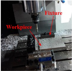
b) After machining in one parameter
3.2.2. Experimental procedure
The machining tests were carried out in the type of down milling operation and dry cutting. At the beginning of the experiments a new tool insert was mounted onto the tool holder. The spindle speed is 800 rpm.
It can be calculated from Table 4 that the cutting force coefficients , and are 1686.5, 428.5 and 618.2 by the shearing action in tangential, radial, and axial direction, respectively, and the edge constants, , are 24.7,42.9 and5.5.
Table 4The cutting test data
Number | Feed per tooth (mm/z) | Depth of cut (mm) | (N) | (N) | (N) |
1 | 0.04 | 1 | 73.82 | 106.54 | 21.33 |
2 | 0.06 | 1 | 98.36 | 123.32 | 54.29 |
3 | 0.08 | 1 | 118.76 | 141.86 | 79.84 |
4 | 0.04 | 2 | 80.59 | 213.29 | 38.18 |
5 | 0.06 | 2 | 104.58 | 279.06 | 78.52 |
6 | 0.08 | 2 | 138.82 | 354.67 | 83.38 |
7 | 0.04 | 3 | 193.25 | 374.35 | 79.13 |
8 | 0.06 | 3 | 240.13 | 480.68 | 98.84 |
9 | 0.08 | 3 | 253.41 | 632.73 | 101.27 |
3.3. Predicted milling forces
The total instantaneous cutting forces are evaluated by integration of the contributions of all the differential edge segments of the tool. Furthermore, the total cutting forces can be derived from the three orthogonal force components in Cartesian coordinates in , and directions as follows:
where, is the tool’s rotational angle; the start angle and the exit angle . , , , , , . , are integral up limit and down limit.
The milling parameters TC4 Thin-walled part are listed as follows: the depth of cut: 2 mm; feed per tooth: 0.05 mm/z; tool diameter: 12 mm, the number of tooth: 1; the radial depth of cut: 0.25 and 0.5. The milling forces of thin-walled part are simulated in different parameters, as shown in Fig. 7. It can be noticed that the milling forces value is not change with the increase of radial depth of cut, but the exit angle increase.
In the experiment of milling force coefficients measurement, the instantaneous cutting forces in three directions are measured by dynamometer and the data has been saved in the computer. Then the data is calculated to obtain the milling force coefficients in regression method. With the milling force coefficients, the stability lobes can be elaborated after getting the modal parameters in modal tests.
Fig. 7Milling forces in x, y and z directions
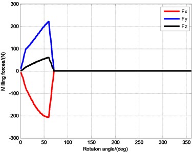
a)0.25
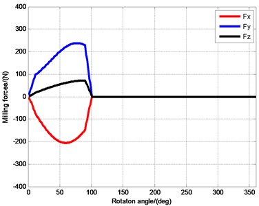
b)0.5
4. Predicted stability charts
Stability lobes are predicted by the semi-discretization (SD) method for up milling and a series of radial immersions based on the stability model. A single set of lobes is observed in the chart in low radial immersion ranges. The stability maxima are located at approximately 3.2, 2.25, 1.75, 1.3.5, 1.18 krpm. This set of lobes corresponds to the Hopf bifurcation instability which causes quasiperodic chatter vibrations. Influences of radial depth of cut on stability lobes. It can be noticed in Fig. 8 that two predicted results are coincident in the , but they are quite different when , particularly in high speed, which belongs to the small radial depth of cut. The decrease of radial depth of cut is, the increase of axial depth of cut is. Since the strength of intermittence, stability zone becomes narrow.
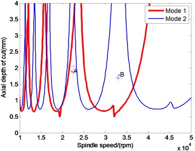
3D stability lobe diagram is simulated by semi-discrete time domain analysis method, which is composed of spindle speed, axial depth of cut and radial depth of cut, as shown in Fig. 9. The stability lobes determined by cutter are represented (Fig. 10) for the first and second modes. Two points are selected for further study.
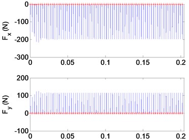
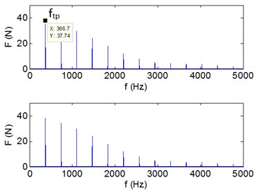
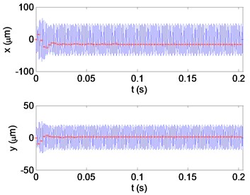
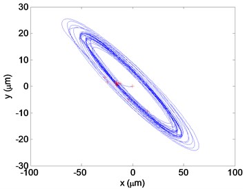
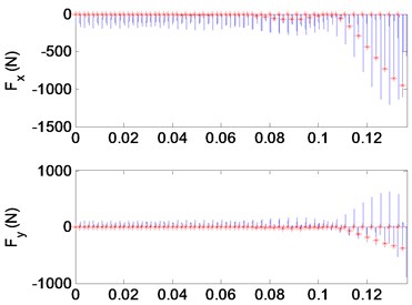
When analyzing the stability of a milling progress, milling forces and vibration displacements for the and directions displacements will be the decision conditions. The datas obtained at the cutting condition A (22000 rpm, 2 mm) in Fig. 10 are shown in Fig. 11 as displacements and forces curves, which a stable cutting progress is represented. Conversely, in Fig. 12, operating parameters of the flip bifurcation for the point B (31000 rpm, 1.7 mm) is shown. The once-per-revolution sampled data (‘*‘symbols) demonstrate quasiperiodic, Hopf instability. Plot of versus direction displacements obtained from the cut. The elliptical distribution of the once-per-revolution sampled data (‘*‘symbols) indicates instability. Shown in the vibration displacements curves, under the cutting condition A, the milling is stable. However, under the cutting condition B, the vibration amplitude increases and the quality of milling progress is quite low. Known from the Fourier spectrum, when the cutting is stable, the vibration frequency is equal to multiple amplitude with the cutter frequency. Under the cutting condition B, vibration frequency is equal to the forced vibration frequency and the filp bifurcation chatter frequency. According to the high speed and interrupted cutting periodic filp bifurcation unstable theory, the chatter frequency shows that the dynamic milling forces and periodic chatter occur, which represents the cutting progress is unstable.
Fig. 8The ZOA and SD stability lobes in low radial immersion milling
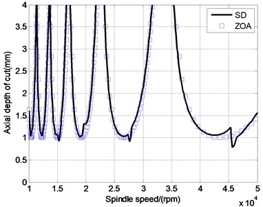
a)0.25,
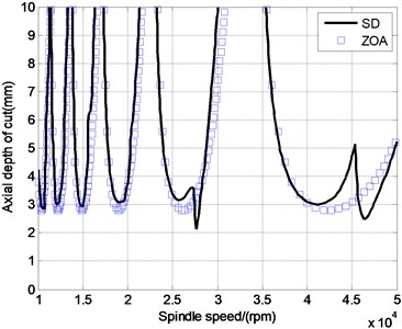
b)0.1,
Fig. 93D stability lobe diagram
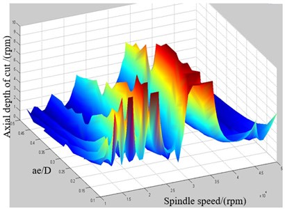
Fig. 10Stability lobes for two modes of cutter (ae= 0.2D)
From the all the above analysis, semi-discrete method does better accuracy than ZOA method in prediction of low radial immersion milling. Consequently, with the radial cutting depth decreasing, milling intermittent enhanced, lobe of stability is gradually narrowed, which will broaden chatter zone. And it is more accurate to apply the semi-decrete time domain analysis to determine the stability area in low radial cutting depth machining. For example, when the spindle speed is 40000 rpm, under the conclusion got by semi-decrete method, the axial cutting depth can be 1.5 mm or more ( 1.5 mm) without chatter. However, the depth can only be selected at 1mm or less ( 1 mm) according to the ZOA method. Consequently, a higher efficiency in thin-walled parts milling progress can be achieved, which is the goal of milling parameters optimization.
Fig. 11The milling forces and vibration displacements in point A (22000 rpm, 2 mm)
a) Milling forces in and direction
b) FFT in in and direction
c) The displacement in and direction
d) The versus direction displacement
Fig. 12The milling forces and vibration displacements in point B (33000 rpm, 1.7 mm)
a) Milling forces in and direction
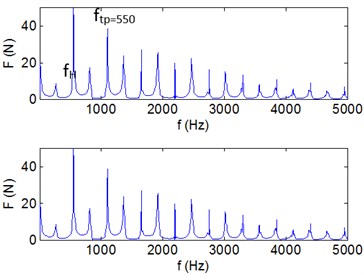
b) FFT in in and direction
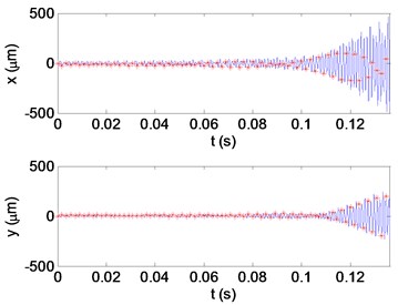
c) The displacement in and direction
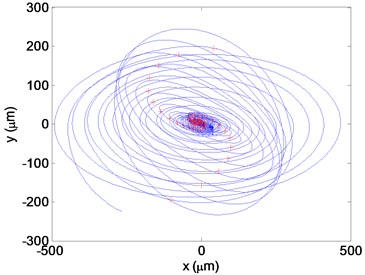
d) The versus direction displacement
5. Conclusions
The chatter stability condition in high-speed milling is closed relative to among spindle speed and depth of cut, besides cutter geometry, engagement conditions, frequency response function, material property of workpiece and so on. For the high-speed machining system, the stability model is relative to high-order dynamic behaviour of multi-DOF system.
The dynamic model and the critical condition of stability determined by the relative dynamic characteristics between cutter subsystem and thin-walled subsystem are proposed to obtain the reasonable and accurate stability domain.
For those concerned with detailed process modeling, the exact nature of milling instability (Hopf or flip bifurcation) is extremely interesting. In thin-walled part milling, the radial depth of cut has to be considered. When the radial depth of cut is low, additional stable zones appear that “split” the higher radial depth stability lobe.
Since the variation of the dynamic parameters of thin-walled part due to material removal and the use of deformable tool and wear, it is necessary to integrate into the stability lobes model by tracing the dynamic behaviour variation of with during diverse machining stages.
References
-
Niroomand M. R., Forouzan M. R., Salimi M. Frequency analysis of chatter vibrations in tandem rolling mills. Journal of Vibroengineering, Vol. 14, Issue 2, 2012, p. 852-865.
-
Zhu L. D., Li H. N., Wang W. S. Research on rotary surface topography by orthogonal turn-milling. International Journal of Advanced Manufacturing Technology, Vol. 69, 2013, p. 2279-2292.
-
Budak E., Çomak A., Öztürk E. Stability and high performance machining conditions in simultaneous milling. CIRP Annals – Manufacturing Technology, Vol. 62, Issue 1, 2013, p. 403-406.
-
Biermann D., Kersting P., Surmann T. A general approach to simulating work-piece vibrations during five-axis milling of turbine workpieces. CIRP Annals – Manufacturing Technology, Vol. 59, 2010, p. 125-128.
-
Kersting P., Biermann D. Modeling techniques for simulating work-piece deflections in NC milling. CIRP Journal of Manufacturing Science and Technology, Vol. 7, 2014, p. 48-54.
-
Altintas Y., Stepan G., Merdol D., Dombovari Z. Chatter stability of milling in frequency and discrete time domain. Annals of the CIRP, Vol. 53, Issue 1, 2008, p. 35-44.
-
Altintas Y., Eynian M., Onozuka H. Identification of dynamic cutting force coefficients and chatter stability with process damping. CIRP Annals – Manufacturing Technology, Vol. 57, 2008, p. 371-374.
-
Pogacink M., Kopac J. Dynamic stabilization of the turn-milling process by parameter optimization. Proceedings of the Institution of Mechanical Engineers Part B Journal of Engineering Manufacture, Vol. 214, 2000, p. 127-135.
-
Thevenot V., Arnaud L., Dessein G. Integration of dynamic behavior variations in the stability lobes method: 3D lobes construction and application to thin-walled structure milling. International Journal of Advanced Manufacturing Technology, Vol. 27, Issue 7, 2006, p. 638-644.
-
Budak E. Improving productivity and part quality in milling of titanium based impellers by chatter suppression and force control. Annals of the CIRP, Vol. 49, Issue 1, 2000, p. 31-36.
-
Budak E., Tunc L. T., Alan S., Ozguven H. N. Prediction of workpiece dynamics and its effects on chatter stability in milling. CIRP Annals – Manufacturing Technology, Vol. 61, Issue 1, 2012, p. 339-342.
-
Budak E., Ozturk E., Tunc L. T. Modeling and simulation of 5-axis milling processes. CIRP Annals – Manufacturing Technology, Vol. 58, 2009, p. 347-350.
-
Budak Erhan, Tunc Taner, Alan Salih Prediction of work-piece dynamics and its effects on chatter stability in milling. CIRP Annals-Manufacturing Technology, Vol. 61, 2012, p. 339-342.
-
Erdem Ozturk, Erhan Budak Dynamics and stability of five-axis ball-end milling. Journal of Manufacturing Science and Engineering, Vol. 132, 2010, p. 1-13.
-
Song Q., Ai X., Tang W. Prediction of dynamic stability limit of time-variable parameters system in thin-walled workpiece high-speed milling processes. The International Journal of Advanced Manufacturing Technology, Vol. 55, Issues 9-12, 2011, p. 883-889.
-
Tang A., Liu Z. Three-dimensional stability lobe and maximum material removal rate in end milling of thin-walled plate. International Journal of Advanced Manufacturing Technology, Vol. 43, Issues 1-2, 2009, p. 33-39.
-
Bravo U., Altuzarra L. N. Stability limits of milling considering the flexibility of the workpiece and the machine. International Journal of Machine Tools and Manufacture, Vol. 45, 2005, p. 1669-1680.
-
Liang R., Ye W. Thin-walled parts to predict and verify the stability of high-speed milling. Journal of Mechanical Engineering, Vol. 45, Issue 11, 2009, p. 147-148, (in Chinese).
-
Insperger T., Stepan G. Updated semi-discretization method for periodic delay-differential equations with discrete delay. International Journal for Numerical Methods in Engineering, Vol. 61, 2004, p. 117-141.
-
Govekar E., Gradisek J., Kalveram M. On stability and dynamics of milling at small radial immersion. CIRP Annals Manufacturing Technology, Vol. 54, Issue 1, 2005, p. 357-362.
-
Schmitz Tony L., Smith K. Scott Machining Dynamics. Springer, 2008.
Cited by
About this article

This work was supported by (National Natural Science Foundation of China) NSFC (51105072) and (51475087), supported by Fundamental Research Funds for the Central Universities (N150304005) and (N140301001), and Education Department of Liaoning Province Key Laboratory Project (LZ2014016).
