Abstract
In order to protect rotors and foil bearings operating at high temperatures from being overheated and damaged, these components are often cooled by air. In addition, such a cooling method is accompanied by an axial temperature gradient that changes the shape of the lubrication gap in a way likely to affect the operation of a foil bearing. This article presents the research on various methods for cooling a foil bearing and discusses the impact of these methods on dynamic parameters of the rotor-bearings system. To be able to assess the temperature inside such a bearing, there is a need for a reliable measurement method. The authors of the article measured the temperature of the top foil using thermocouples and showed that their measurement method does not exert any significant impact on the operation of the rotor-bearings system. The article also describes a novel method for compensating the axial temperature gradient occurring in the bearing bush using Peltier modules.
1. Introduction
New requirements which any microturbine must meet (such as low weight, the ability to operate at high temperatures and/or rotational speeds) are related to the need to find bearings that can withstand such harsh conditions. Foil bearings are becoming more and more popular and are now being applied increasingly frequently to industrial machines [1] or in the aviation industry [2]. Such bearings are often research subjects. Research teams from all over the world conduct research on the resistance to high temperatures of foil bearings. High temperatures acting on a foil bearing can change its properties [3] or even lead to damage to the load-carrying layer [4]. One way to move heat away from the bush-shaft area is to apply forced cooling air streams that flow in the axial direction through the bearing. Recent studies show that this method proves to be quite efficient but can also cause changes in the dynamic behavior of a rotating journal or of the entire shaft-foil bearings system [5].
In 2001, Salehi and Heshmat [6] used a compliant gas foil seal and a hybrid foil/ball bearing in a small gas turbine simulator. The bearing and the seal operated successfully at temperatures up to 560 °C and speeds up to 55,000 rpm. At the hot section of the machine (560 °C), an oil-free foil bearing was installed and at the cold (compressor) section of the machine, an oil mist lubricated ball bearing was mounted. The surface of the top foil was coated with an antifriction material (PS304 solid lubricant film). The seal was subjected to many tests at different operating temperatures and speeds. The tested foil bearing exhibited very good damping properties (even at high temperatures) and there was no evidence of wear on the journal or seal surface. It is one of the first attempts to test out a foil bearing under high temperature.
Walton et al. [7] conducted the research on a rotor designed to simulate a very small turbojet engine or turbocharger rotor. Weighing just approx. 400 g, the rotor was tested at speeds up to 150,000 rpm. It was supported by third generation foil bearings. One of the tests that were conducted consisted in a series of accelerations/decelerations from 75,000 rpm to 150,000 rpm as a stream of air at 345 °C was supplied by the heaters and was flowing through both thrust bearings to the journal bearing until it reached the target temperature of 290 °C. It was noticed that the bearing temperature increases as the rotational speed rises. In article [8] that was published a year later, the same authors described tests carried out on a turbojet engine in which the rolling bearing and its lubrication system (situated at the hot side) were replaced with an air foil bearing. The purpose was to assess the ability of the foil bearing to operate in an extremely difficult environment (i.e. varying temperatures and loads). After numerous tests at speeds up to 60,000 rpm and temperatures up to 650 °C, the bearing and journal showed no evidence of rubs or surface degradation. The bearing was air-cooled. It was found that when the airflow rate is below 140 L/min, bearing temperatures continued to increase with no indication of stabilising. An axial thermal gradient of 13 °C/cm was the maximum permissible gradient across the bearing. Such a high axial gradient causes an unfavourable change in the lubrication gap geometry and can lead to a damage to the bearing.
The problem of heat surplus in foil bearings is also present in industrial applications [9, 10]. A turbocharger that includes a foil bearing assembly is described in [9]. This bearing assembly includes a foil thrust bearing assembly disposed between two foil journal bearings. All bearings are air-cooled. The cooling system was designed in such a way to avoid overheating the foil coatings. One method for ensuring that a long useful life of a foil bearing can be achieved is to cover some of its components with a sliding coating made of a plastic material. Article [11] demonstrates that a low coefficient of friction between the bearing components helps to reduce the amount of heat generated by friction, thereby improving the dynamic performance of the bearing.
Next study presented in paper [11] shows what can happen when there is not adequate cooling provided to a gas foil bearing. A test rotor was supported by two foil bearings operating with a heated shaft. An electric cartridge heater was inserted into the hollow shaft. The bearings were mounted in one casing so as to guarantee of the two bearing bushes, which is important for the proper functioning of the entire system [2, 12, 13]. The heater's set temperature maximally equaled 600 °C and the maximum temperature registered by thermocouples placed on the bearing sleeve was approx. 120 °C. The operation of the rotor at a speed of 37,000 rpm, lasting several hours, led to a damage of the foil bearing and the rotor stopped abruptly. Paper [14] describes a method preventing the rotor-bearings system from overheating. Experiments were conducted with forced streams of air cooling the bearings and rotor. The parameters that were changed are as follows: rotational speed and the amount of cooling air supplied to the bearings. It was found that a flow rate below 300 L/min exhibits a poor cooling capability (0.05 °C/L/min). It was observed that such a cooling method brings the best effects at the free end of the shaft when it rotates at a maximum speed. The dynamic behaviour of the system was analysed as well. It was concluded that the air streams flowing through the bearings (irrespective of the flow parameters) have virtually no effect on the system operation. It was also observed that the cooling air streams do not affect either vibration amplitudes/trajectories of the rotor or its eigenfrequencies.
This article presents the research focused on several methods for decreasing temperature of a foil bearing. An efficient method for the measurement of temperature and the thermal gradient of the top foil was also shown. The authors also discuss the issues related to operating parameters of the rotor-foil bearings system and the impact of the ambient temperature of its functioning.
2. The research rig and measurement method
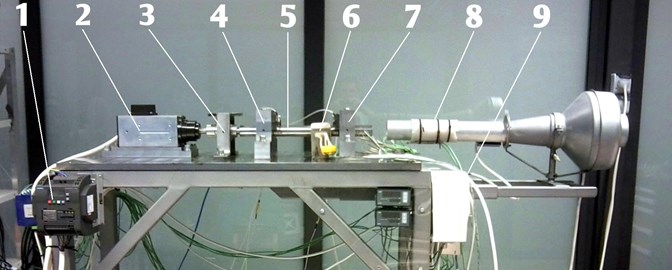
The dynamics of the rotor-foil bearings system was examined using a test stand designed and constructed at the Department of Turbine Dynamics and Diagnostics (Fig. 1). The test stand’s components were fixed to a massive steel plate that rests on the load-bearing structure. The plate and the supporting structure have a similar shape to a table. The frame is constructed from steel profiles and is equipped with vibration isolation feet. The bearing supports and sensor holders are mounted on the Teflon-coated plate. The rotor is driven by a high-speed electro-spindle that is equipped with ceramic bearings and enables a maximum speed of 24,000 rpm. A steel shaft weighing 3 kg is connected to a 3 kW motor using a jaw coupling with elastic inserts. The rotor is supported by two radial foil bearings with a diameter of 34 mm, placed inside bearing supports. The bearing supports are composed of two parts, thus enabling rapid exchange of investigated bearings. A structural analysis of the test rig shown in Fig. 1. A heating device consisting of a heating tube and a duck fan, named “heat gun”, is located in the immediate vicinity of bearing node no. 2 (at the free end of the shaft). During the research described herein, the heaters of this device were not used. From now on this unit will be called “air blower” (see Fig. 1). This device generates air streams for cooling the system. Both the flow rate and temperature of forced air streams can be adjusted.
Fig. 1General view of the test stand without thermal shields mounted: 1 – speed controller, 2 – drive motor (electro-spindle), 3 – coupling, 4 – bearing support no. 1, 5 – rotor shaft, 6 – infrared emitters, 7 – bearing support no. 2, 8 – air blower, 9 – heating devices control system
In order to be able to assess the impact of cooling the foil bearing on its operation, the temperature of the bearing foil (more precisely, in the lubricating film) must be known. After many attempts of measuring the temperature, thermocouples were placed inside the bush in such a way that their tips remain in contact with the outer surface of the top foil. Thanks to this approach, it was possible to measure the lubricating film temperature. First measurements aimed to determine whether and in what manner the used method for measuring the temperature affects the dynamic performance of the investigated system. For this purpose, displacements and temperatures of the shaft were measured for two system configurations and then compared with each other. In the first configuration, both bearings operated without any thermocouples mounted, whereas, in the second, one of the bearings had thermocouples mounted within its bush. The arrangement of thermocouples is shown in Fig. 2 and the method of affixing them is described in paper [11].
Fig. 2a) photo of the tested foil bearing, b) the arrangement of thermocouples inside the bush [11]
![a) photo of the tested foil bearing, b) the arrangement of thermocouples inside the bush [11]](https://static-01.extrica.com/articles/19772/19772-img2.jpg)
a)
![a) photo of the tested foil bearing, b) the arrangement of thermocouples inside the bush [11]](https://static-01.extrica.com/articles/19772/19772-img3.jpg)
b)
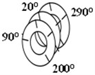
The Fig. 3 shows the position of the thermocouples in the bearing. On the left picture, there is a close-up of the bearing node situated at the free end of the shaft. Additionally, the angle values of the notches (in which the thermocouples are located) are indicated. On the right picture, we can see the numbering of the planes on which the temperature was measured. This designation allows for a more accurate location of the temperature sensors in the bearing.
Fig. 3Position of the thermocouples in the bearing
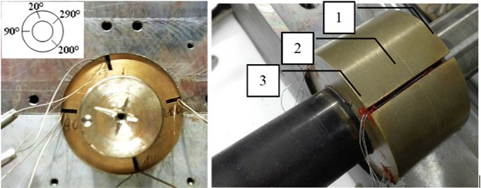
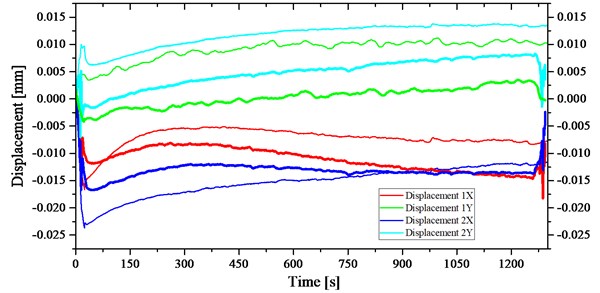
Fig. 4 demonstrates displacement of the shaft measured during the rotor-bearings system’s operation versus time. Readings from sensors located inside bearing no. 1 are shown in red and green, whereas the shaft displacements registered at bearing no. 2 (located at the free end of the shaft) are shown in blue and turquoise. All curves in Fig. 4 represent centerlines between maximal and minimal vibration values. Displacement values obtained during system operation without any thermocouples mounted are presented using thin lines and the thick lines show the values measured for the case in which thermocouples were mounted inside bush of bearing no. 2. The curves in Fig. 4 show displacements of the shaft from an eddy current sensor. Adding thermocouples to the system caused the displacement of bearing journal no. 2 in the direction and almost doubled the displacement of bearing journal no. 1 in the direction. Despite such differences, the system's operation was stable all the time. It is not possible to establish clearly which system configuration functioned better: the one with thermocouples or the one without thermocouples.
Fig. 4Shaft displacement in two directions, registered when thermocouples were (thick lines) and were not (thin lines) mounted inside the bushes vs. time
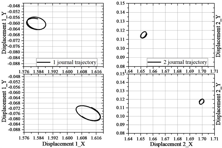
The foil bearing has adapted the shape of its lubrication gap so as to better face the new operating conditions (Fig. 4) that resulted from the existence of additional system components-thermocouples interacting with the top foil. Under new operating conditions, the vibration trajectory registered for bearing no. 2 has a very similar shape and size but its position within the bush differs by approximately 50 µm. Adding thermocouples to the second bearing has affected the functioning of the first bearing as well. The vibration trajectory measured for bearing no. 1 is larger by several µm and its location differs by approx. 30 µm.
Fig. 5Vibration trajectories of both bearings with and without thermocouples mounted inside their bushes, registered during the operation at a speed of 24,000 rpm (1250th second of the measurement): left column – bearing no. 1, right column – bearing no. 2, upper row – thermocouples are not mounted, lower row – thermocouples are mounted
The other parameters that were taken into consideration in this study were temperatures registered at two ends of the shaft (i.e. at free and driven end) using optical sensors (Fig. 6). The thin lines indicate the temperatures obtained for the first system configuration, whereas thick lines show the temperatures measured during the operation of the system including thermocouples. Irrespective of whether thermocouples are a part of the system or not, the temperature measured at the free end of the shaft remains virtually unchanged. The surface temperature of the shaft near the coupling increased by approximately 2 °C after 700 seconds from the start of the measurement and this rise is closely related to the increase in shaft displacement in bearing no. 1.
Fig. 6Temperature at both ends of the shaft, measured when thermocouples were (thick lines) and were not (thin lines) mounted inside the bushes vs. time
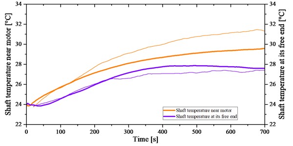
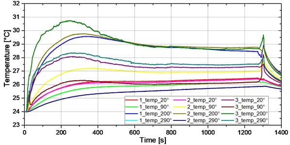
Fig. 7 presents temperatures registered by thermocouples mounted inside bearing no. 2. A rapid increase in the bearing temperature occurred during the rotor run-up when the lubricating film was forming itself and it was followed by the temperature stabilisation when the shaft rotated at its maximal speed. The highest temperature has been registered by the thermocouple placed at the angular position of 200°. The first digits in the legends of the figures showing measured temperature values denotes the placement of thermocouples inside the bearing, and the last digits denote the circumferential positions of temperature sensors (according to Fig. 3).
The theoretical minimum lubricating gap is 10 µm. Thermocouples inserted into the bush holes, which are in contact with the outer surface of the top foil, have an impact on the dynamic performance of the system since they alter the lubricating gap. As a result, different locations of journals within the bushes as well as vibration trajectories of other shapes were observed. Having examined the above temperature and journal displacement graphs, it can be said that the measurement method used performs exceptionally well in our tests and does not have an adverse effect on the functioning of the tested system.
Fig. 7Temperatures registered by thermocouples mounted inside the bush vs. time

3. The influence of cooling methods on the rotor-foil bearings system operation
In this chapter, several methods for lowering the temperature of a foil bearing are presented. The first two methods consisted in using forced air streams directed towards the free end of the shaft, in the vicinity of which is bearing no. 2. The third method employs Peltier modules mounted on the bush of bearing no. 2. This method was applied to reduce the temperature gradient on the top foil, but in this case also helped to temporarily cool the bearing.
3.1. Cooling the foil bearing using the air blower
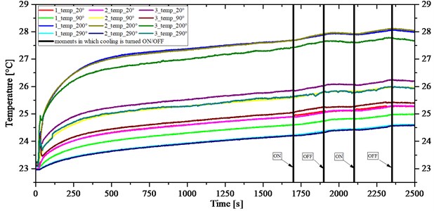
Forced air streams were generated using a heat gun with the heater turned off. The air blower outlet was directed towards the free end of the shaft. The first experiment consisted in accelerating the rotor to the maximal rotational speed and then continuing the operation until the temperature in the bearing stabilises itself. Once 1,500 seconds passed, the blower was turned on and then, after about 500 seconds, it was turned off. The measurement lasted approximately 2,400 seconds. We aimed to observe changes in dynamic characteristics and temperature of the bearing during its cooling using forced air streams. Fig. 8 shows journal displacements presented as functions of time. Four black vertical lines indicate moments of time in which the blower was turned on or off. It can be said that cooling the bearing using air streams has an impact on the operation of the rotor – bearings system. It is only a matter of several dozen seconds and the system responds to temperature changes caused by switching the cooling unit on or off. The journal displacements can be observed in bearings no. 1 and no. 2 (the cooled one) respectively by approx. 5 µm and 8 µm.
Fig. 9 presents temperatures registered inside the bearing subjected to forced air cooling using the air blower. A temperature rise of 0.5 °C was noticed after air streams started flowing through the bearing. After the cooling unit was turned off, the temperature remained at the same level. During the next cycle, the temperature increased slightly. The unexpectedly rising temperature is likely attributable to a minimum voltage supplied to the heating coil and/or the blower motor. The operating motor generated heat and the sucked-in air was flowing through it. The heat removed from the cooling unit was supplied to bearing no. 2. It was decided to repeat measurement in order to confirm our suppositions. Fig. 10 demonstrates results of the measurement similar to the one described above. It was noticed that the temperature increased and the blow-in of air that was warmer than the air located within the bearing has an impact on the system.
Fig. 8Shaft displacement (in two directions) of the shaft subjected to forced air cooling using the air blower’s fan vs. time
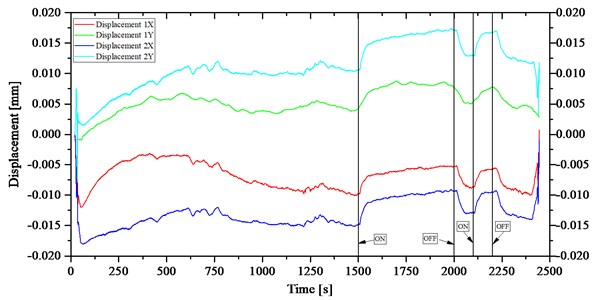
Fig. 9Temperatures recorded inside the bearing subjected to cooling using the air blower’s fan vs. time
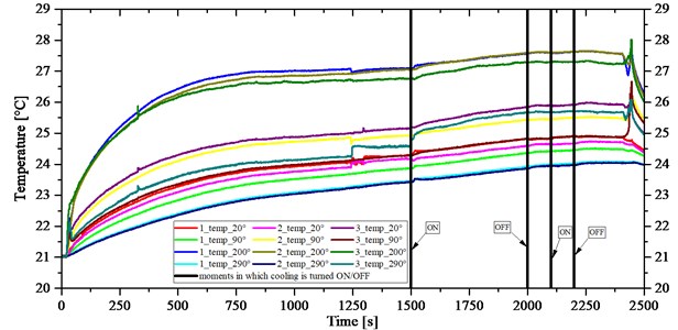
Fig. 10Temperatures recorded inside the bearing subjected to cooling using the air blower’s fan vs. time-measurement conducted again
All temperature rises that can be seen in Fig. 9 are caused by the wearing-in process of the bearing, i.e. adapting the foils to the system’s operating conditions. The changes in temperature correspond to journal displacements demonstrated in Fig. 8.
The second temperature measurement confirmed our suppositions about a temperature rise inside the bearing following a switching-on the air blower. The rotor displacements registered during this experiment (not presented herein) are very similar to the ones shown in Fig. 8, both in terms of values and journal locations within the bush. As the tests show, the air blower is not suitable for cooling the bearing in the tested temperature range. We do believe though that it would perform well in elevated temperatures. In spite of different temperature fluctuations occurring during subsequent ON/OFF cycles, the journal displacement values were very similar – in terms of both and directions.
3.2. Cooling the foil bearing using an air circulator fan
The research was conducted in a similar way to the experiments described in chapter 3.1, with the only change being the bearing cooling device. This time, the bearing was cooled by means of an air circulator placed near the free end of the shaft. We carried out measurements of journal displacements and temperatures inside the bearing in such a way that the temperature stabilisation in the bearing is first ensured and then results are recorded (Fig. 11). The bearing operated at a speed of 24,000 rpm for about 30 minutes. The journal locations at the time when the measurement began are deemed to be zero.
Fig. 11Shaft displacement (in two directions) of the shaft subjected to cooling using an air circulator fan, measured during the operation at a speed of 24,000 rpm vs. time
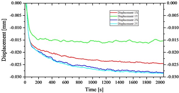
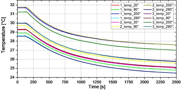
The journal displacement of bearing no. 1 was maximally 15 µm in the direction and 24 µm in the direction. The journal displacement in the second bearing was approx. 26 µm in both directions. Fig. 12 presents temperatures registered by thermocouples mounted inside the bearing operating at a rotational speed of 24,000 rpm. After 2,500 seconds of the measurement, the temperature decreased by approximately 4 °C but the nature of temperature distribution on the top foil’s surface remained the same. During the first 100 seconds, the system exhibited a stable operation.
In the previous experiment, the air blower increased the bearing temperature and the journal moved closer to the sensors. It turns out that the air circulator caused a drop in the bearing’s temperature and the journal moved away from the sensors. Differences in journal displacements are caused by different temperatures occurring during cooling using the air blowers fan and the air circulator. The air blower increased the temperature of the top foil very slightly (by approx. 1 °C) and the journal displacements were small and did not surpass 8 µm. After the temperature changed by approx. 4 °C, the cooled journal also changed its position by approx. 26 µm.
Fig. 12Temperatures registered by thermocouples mounted inside the bush during the operation at a speed of 24,000 rpm vs. time
3.3. Cooling using thermoelectric modules
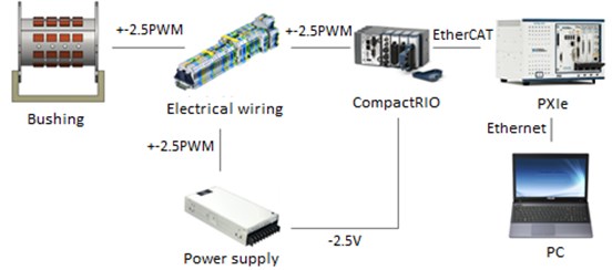
Although the use of thermoelectric coolers (TEC) is vastly spread in consumer electronics, precise measurement equipment and even in medicine, it is new to the temperature management of foil bearings [15, 16]. To achieve the proper granularity of control, the modules integrated into the bearing were arranged in a matrix of 9×4 modules along the circumference and the longitudinal axis, respectively. The principle of operation of the presented method can be summarized as follows: each TEC is independently controlled by the PWM (Pulse Width Modulated) signal and while acting as a heat pump it can locally influence the heat flux and in effect the temperature distribution. At the hot spots location, the heat is removed with higher transfer rate, what eventually causes the temperature unification around the most vulnerable bearing’s components – the foils. The overall temperature of the bearing may, however, rise due to the Joule effect. As the foil bearing can operate flawlessly even at higher temperatures [17] it is the temperature gradient that is proved to be detrimental and as such its effects are mitigated due to the proposed control scheme. Fig. 13 shows the control system architecture that was built based on the National Instruments platform. The system consists of the foil bearing with integrated TEC modules, a 2.5VDC power supply, I/O modules and a PXIe controller that runs the control algorithm. The modulated current is sourced by the NI 9144 controller equipped with 9478 C-series modules. The temperature readings are provided by a temperature acquisition module (PXIe-4353). The communication between the PXIe and NI 9144 is provided via EtherCAT protocol. The operator panel and the data acquisition module are run on a PC computer [18].
Fig. 13TEC modules control scheme
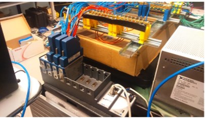
The test stand was modified in such a way that TEC modules were first integrated into the foil bearing’s bushing and then the whole bearing was mounted to the shaft as well as the control system’s wiring was installed. Fig. 14(a) shows the foil bearing with integrated TEC modules and thermocouple sensors. The thermocouple sensors tips were inserted into the inspection holes and glued by silicone what was necessary to assure good contact between the sensors and the top and bump foils of the bearing and get reliable readings. Fig. 14(b) shows the assembled bearing with the shaft. The screw terminals provided control over the TEC module polarization – the configuration of which was controlled manually before each test loop. The thermocouples sensors were connected directly to the PXIe controller. The system requires almost 100 conductors. The small outer dimensions of the bearing make starting the system difficult.
Fig. 14a) Thermoelectric modules and temperature sensors integrated into the bearing bush; b) general view of the test rig and its control system
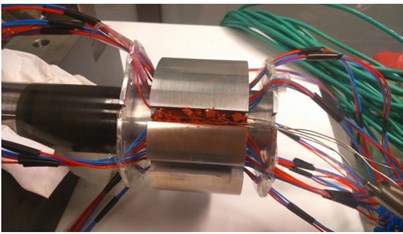
a)
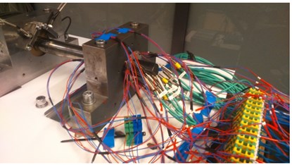
b)
Fig. 15 presents the part of the test stand responsible for powering and controlling TEC modules. Each 2.5Vp PWM signal was generated using NI 9144 controller equipped with the 9478 C-series sinking output.
Fig. 15a) TECs and thermocouples wiring connected to the control module; b) NI's modules that generate PWM signals
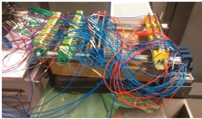
a)
b)
Fig. 16 shows numbering and locations of thermocouple sensors and TEC modules. The modules were grouped circumferentially into the 9 groups and numbered from P1 to P9. Each module from the same group was controlled by the current with equal PWM fill factor. Temperature sensors were placed in notches made within the bearing bushing. Due to the bump foil’s construction only three sensors could be used to conduct measurements on the top foil and four on bump foil along the bearing axis. Moreover, due to space limitation the locations of bump and top foil measurement points are interchangeably and evenly located around the bearing circumference as illustrated in the figure below.
The bush was mounted inside the bearing support. Control and collection of operating data were done using a SCADAS system. The figures below present the results such as journal displacements and temperatures that were obtained for different operating modes of TEC modules. Fig. 17 demonstrates the displacement of two bearing journals versus time, where zero means a value set during a stable operation. The time intervals during which TEC modules were switched on are marked by numbers from “1” to “4”. During the whole measurement, the displacement of journal no. 1 is 3 µm and 7 µm depending on the direction. When TEC modules were turned on, displacements of journal no. 1 were very small and close to the measurement accuracy of sensors (i.e. around 1 µm). In bearing no. 2 in which TEC modules were installed, the maximum displacement of the journal was below 1 µm or 2 µm, respectively, when the modules were on or off.
Fig. 16The numbering of TEC and thermocouple sensors [18]
![The numbering of TEC and thermocouple sensors [18]](https://static-01.extrica.com/articles/19772/19772-img21.jpg)
Fig. 17Shaft displacement of the bearing journals in two directions vs. time. The measurement ranges are indicated by black vertical lines
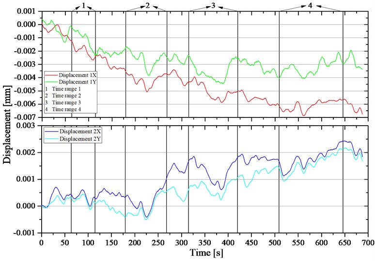
Fig. 18 presents the temperatures measured during the experiment in which TEC modules placed at the top of the bush (i.e. the ones denoted by ‘P1’, ‘P2’, and ‘P9’) ran at half of their rated power. This experiment lasted approx. 50 seconds and its duration is denoted by “1” in Fig. 17. Temperatures were registered by two sets of thermocouples. The first one includes the temperature sensors marked TC0 … TC3 and placed within one notch, the second one includes sensors marked TC4 … TC6 and located inside the next notch. Both these notches are situated between sets of TEC modules. After switching on the selected TEC modules temporarily, a temperature drop by about 1.5 °C was registered on the top foil’s surface.
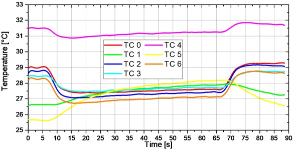
Fig. 19 presents the temperatures measured during the experiment (the duration of which is marked by “2” in Fig. 17) in which three TEC modules sets (the same as the ones in the previous experiment) operated at half of their rated power. This time, the experiment duration is approximately 90 seconds. The measurement duration has been extended so as to check for how long TEC modules are able to cool the bearing. Temperature drops were in the range 0.5-1.5 °C, similarly as in the first experiment. After about 20 seconds, TEC modules started to lose the ability to cool the bush surface and even began to heat it, as can be seen from the graph in Fig. 19. Although the overall temperature scatter didn’t tend to increase throughout the whole TECs activation period.
Fig. 18Temperatures registered when three sets of TEC modules marked by ‘P1’, ‘P2’ and ‘P9’ operate at half of their rated power vs. time. Experiment marked by “1” in Fig. 17
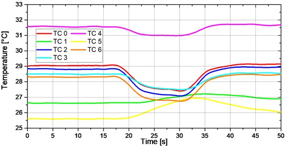
Fig. 19Temperatures registered when three sets of TEC modules marked by ‘P1’, ‘P2’ and ‘P9’ operate at half of their rated power vs. time. Experiment marked by “2” in Fig. 17
The next experiment consisted in running all TEC modules at half of their rated power and registering temperatures using all thermocouples (Fig. 20). All but five thermocouples showed temperature drops. The drops in temperature were in the range of 1.5 °C to 2 °C. After about 10 seconds of the operation of TEC modules, the temperature started to rise. Some sensors recorded temperature rises as soon as the TEC modules were switched on and temperature drops after they were switched off. This could have been due to a poor installation method of some thermocouples because other thermocouples located in their vicinity recorded temperature drops.
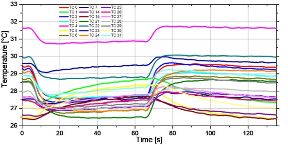
During the experiment, the results of which are shown in Fig. 21, all TEC modules in all sets operated at 30 % of their rated power. The drops in temperature were in the range of 1 °C to 1.5 °C.
During the research, many operating modes of thermoelectric modules integrated into the foil bearing's bush were subjected to tests. For several configurations, a considerable reduction in the axial temperature gradient on the top foil’s surface has been achieved. The article presents only selected configurations, in other words, only the ones that yielded the most interesting results. It was observed that changing temperature of a foil bearing using TEC modules has virtually no effect on its dynamic performance. The presented new method of cooling the bearing is original and effective but heat recovering from the bearing is hampered by the hot bush. In order to make this method more effective, a system capable of recovering heat from the bearing node would be needed.
Fig. 20Temperatures registered when all TEC modules operate at half of their rated power vs. time. Experiment marked by “3” in Fig. 17
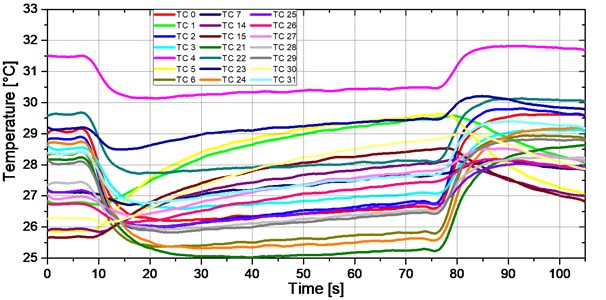
Fig. 21Temperatures registered when all TEC modules operate at 30 % of their rated power vs. time. Experiment marked by “4” in Fig. 1
4. Conclusions
In the article, several methods for cooling a foil bearing have been presented. The main purpose of the research was to check whether cooling the bearing (recovering heat from the inside of one of the bearings) affects the functioning of the entire rotor – bearings system. The focus was on the comparison of themselves methods. The air blower is not suitable for decreasing temperature of the bearing operating at room temperature since forced air streams had a higher temperature than the air in the lubricating gap. However, it was found that the airflow through the bearing is accompanied by a change in the bush journal location. A supposition can be made that air streams (irrespective of their temperature) affect the dynamic performance of the system by changing the conditions existing in the lubricating gap. It seems that only high changes in the ambient temperature around a foil bearing may play a big role in its operation. In the research tackled in chapter 3.3, the bearing temperature has been reduced by approx. 2 °C and displacements of the journals were small enough that could be neglected. When it comes to experiments conducted using the air blower’s fan, a change in temperature by approximately 1 °C resulted in a journal displacement of about 7 µm. Given that the thickness of the lubricating gap is around 10 µm, this is quite a high displacement. It seems that forced air streams flowing through the bearing could be used not only to control its temperature but also the shaft location within the bush.
Using an air circulator fan has proven to be the most efficient way to cool the bearing. Drops in temperature were the highest in comparison to other cooling methods. Since this research is only of a preliminary nature. But it is sure that both the air quantity and velocity were significantly higher when an air circulator fan was used. As a result of that fact, and as predicted, displacements of the journal within the bush were proportionately higher than the ones measured in the case with the air blower turned on. It would be interesting to know how effective each method described in the article would be if we would use it for cooling a bearing that operates at elevated temperature. The method for equalising temperature gradients or reducing the bearing temperature using TEC modules appears to be rather complex and time-consuming but it is technically feasible and development-oriented. The article presents the method of cooling the bearing which does not affect the dynamics of the rotor. On the other hand, knowing that the temperature of air streams directed to the bearing can have an impact on the position of its journal, it is possible to design a system that would control the position of the shaft, thus supporting the operation of the rotor.
The method used for measuring the temperature within the bearing, strictly speaking – on the top foil’s surface, proved to be a perfect choice. Looking at temperature graphs, we can see how sensitive this method is, where each change in the bearing temperature is accompanied by a journal displacement within the bush. The method permits the determination of a temperature distribution on the foil surface, and thereby in the lubricating film. The research results described in this article should serve to verify numerical models of foil bearings.
References
-
Xiong Lian You, Wu Gang, Chen Chun Zheng, Li Yan Zhong feasibility study on the use of new gas foil hearings in cryogenic turboexpander. Advances in Cryogenic Engineering, Vol. 43, 1998, p. 661-665.
-
Rudloff L., Arghir M., Bonneau O., Matta P. Experimental analyses of a first generation foil bearing: startup torque and dynamic coefficients. Journal of Engineering for Gas Turbines and Power, Vol. 133, Issue 9, 2011, p. 92501.
-
Dellacorte C., Lukaszewicz V., Valco M. J., Radil K. C., Heshmat H. Performance and durability of high temperature foil air bearings for oil-free turbomachinery. Tribology Transactions, Vol. 43, Issue 4, 2000, p. 774-780.
-
Bauman S. An Oil-Free Thrust Foil Bearing Facility Design, Calibration, and Operation. NASA/TM-2005-213568, 2005.
-
Bagiński P., Banaszek S., Żywica G., Kiciński J. Thermal characteristics of the foil bearing operating at elevated temperature during run-up, run-down and constant speed operation. Mechanik, Vol. 7, 2015, p. 21-28.
-
Salehi M., Heshmat H. Performance of a complaint foil seal in a small gas turbine engine simulator employing a hybrid foil/ball bearing support system. Tribology Transactions, Vol. 44, Issue 3, 2001, p. 458-464.
-
Walton J. F., Heshmat H., Tomaszewski M. J. Testing of a small turbocharger/turbojet sized simulator rotor supported on foil bearings. Journal of Engineering for Gas Turbines and Power, Vol. 130, 3, p. 2008-35001.
-
Heshmat H., Walton J. F., Tomaszewski M. J. Demonstration of a turbojet engine using an air foil bearing. ASME Turbo Expo, Power for Land, Sea and Air, 2005.
-
Larue G. D., Wick W., Kang S. Turbocharger with Hydrodynamic Foil Bearings. Patent US 7108488 B2, 2005.
-
Lubell D., Weissert W. Rotor and Bearing System for a Turbomachine. Patent US 7112036 B2, 2006.
-
Zywica G., Baginski P., Banaszek S. Experimental studies on foil bearing with a sliding coating made of synthetic material. Journal of Tribology, Vol. 138, Issue 1, 2015, p. 11301.
-
Feng K., Zhao X. Effects of misalignment on the structure characteristics of bump-type foil bearings: A comparison between experimental and theoretical results. Industrial Lubrication and Tribology, Vol. 67, Issue 4, 2015, p. 370-379.
-
Feng K., Zhao X., Guo Z. Design and structural performance measurements of a novel multi-cantilever foil bearing. Journal of Mechanical Engineering Science, Vol. 229, Issue 10, 2015, p. 1830-1838.
-
Ryu Andrés K. L. S. Effect of cooling flow on the operation of a hot rotor-gas foil bearing system. Journal of Engineering for Gas Turbines and Power, Vol. 7, Issue 10, 2012, p. 497-509.
-
Lubieniecki M., Roemer J., Martowicz A., Wojciechowski K., Uhl T. A multi-point measurement method for thermal characterization of foil bearings using customized thermocouples. Journal of Electronic Materials, Vol. 45, Issue 3, 2016, p. 1473-1477.
-
Roemer J., Martowicz A., Uhl T. Multi-point control method for reduction of thermal gradients in foil bearings based on the application of smart materials. 7th ECCOMAS Thematic Conference on Smart Structures and Materials, 2015.
-
Dellacorte C., Valco M. J. Load Capacity Estimation of Foil Air Journal Bearings for Oil-Free Turbomachinery Applications. NASA/TM-2000-209782, 2000, p. 37-41.
-
Roemer J. Results of Measurements Carried Out on 22-24.02.2016 at Institute of Fluid Flow Machinery. Polish Academy of Sciences in Gdansk, 2016.
Cited by
About this article

