Abstract
Compared with a traditional unilateral-driven large vibrating screen, the proposed dual-side excitation large vibrating screen (DELVS) has a simpler screen structure and less vibration mass, which might improve its reliability. A DELVS with metal cylindrical coiled springs is theoretically and experimentally studied in this paper. With the rotation considered, a fundamental three-degree-of-freedom (3-DOF) dynamic model for DELVS is established firstly. Then an elastic compression bar model method (ECBM) is proposed for transverse stiffness determination of a metal cylindrical coiled spring and applied into the numerical simulation of DELVS. Finally, an experimental test on a DELVS of 4.25 m×6.00 m is conducted. It is seen that numerical simulation with the proposed ECBM is more closely related to the experimental data, hence the accuracy of the proposed dynamic model of DELVS is enhanced. The conclusions may provide guidance on a design of a high-performance large vibrating screen.
1. Introduction
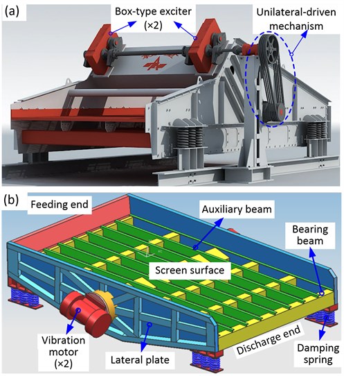
A precise solid-solid separation or an effective solid-liquid separation is widely-used in mineral processing, coal preparation and other industrial processes. Take the vibrating screen in coal preparation for example. It accounts for 30 % of all equipment in coal mine [1, 2]. As shown in Fig. 1(a), the most common unilateral-driven large vibrating screen has a large vibration mass and demands huge exciting force yielded by two box-type exciters. Due to the effect of coupled load consisting of the intense excitation load initiated by exciters, the inertial load of screen structure and the impact load of the screening materials, the dynamic characteristics of such large vibrating screen are extremely complex, and structural damage such as beam fracture or lateral plate crack occurs frequently [3-4]. Therefore, the low reliability and short service life of the equipment can hardly meet the demand for large-scale screening.
The dual-side excitation large vibrating screen (DELVS) proposed in Fig. 1(b) is regarded as having an advantage of a less vibration mass, for the reason that two vibration motors are adopted to replace the two box-type exciters for generating excitation force and to simplify the driven mechanism and screen structure [5]. Two vibration motors with eccentric blocks inside are mounted on the left and right lateral plate, respectively. The excitation force is yielded by rotation of the eccentric block. Note that each group of compression damping spring system of this large vibrating screen contains three outer and three inner metal cylindrical coiled springs (MCCS), which are mounted in a parallel manner.
Proper dynamic model for mechanical design of a large vibrating screen is vital to ensure the reliability and stability of the screen operation. However, as screening performance depends on the stable oscillation in longitudinal vibration, many studies focused more on the longitudinal vibration than on the lateral vibration. Jiang at al. presented a set of dynamic equations governing the longitudinal motion of single-deck equal-thickness vibrating screen, but they didn’t give the numerical simulation of vibration response [5]. Aiming at a DELVS, Despotović et al. proposed a technical solution to adjust the frequency and amplitude of vibration by a control system, and they determined the longitudinal amplitude-frequency characteristics of this vibrating screen without any dynamic model [6]. Baragetti proposed a dynamic model of a vibrating screen for the selection of inert materials in an asphalt plant [7]. Also, he conducted the dynamic analysis in order to proceed with the optimal design of the new modified screen [8]. However, the vibrating screens he considered is a traditional one similar with the unilateral-driven large vibrating screen. In this paper, the theoretical analysis of DELVS will be conducted after a three-degree-of-freedom (3-DOF) dynamic model established firstly. To verify the accuracy, numerical simulation and experimental study will be adopted, and among which, the key dynamic parameter, namely, the fundamental transverse stiffness of MCCS needs to be determined. To improve the accuracy of DELVS, we will propose a new transverse stiffness calculation method instead of a traditional method.
Fig. 1Two kinds of large vibrating screen: a) unilateral-driven large vibrating screen, b) dual-side excitation large vibrating screen (DELVS)
2. Theoretical analysis of DELVS
In this paper, the size of experimental DELVS is 4.25 m×6.00 m. Fig. 2 depicts the dynamic model of DELVS. Here a cartesian coordinate system is established at the center of mass (denoted by ). When the eccentric blocks rotate symmetrically, the resultant force (denoted by ) in -direction (-axis) is zero. As has a certain angle, i.e., to the -direction (-axis), the screen structure experiences a synchronous horizontal and vertical vibration.
Due to the large span between the compression damping spring system of the feeding end and the discharge end, the rotation around -axis might have a great influence on the horizontal and vertical motion. Thus, it is necessary to count the deformation component of the spring caused by rotation when we consider its elastic restoring force in horizontal and vertical direction [9, 10]. On this basis, a 3-DOF dynamic model for DELVS is presented in Fig. 2. It is established based on a traditional model for a vibrating screen, such as a unilateral-driven large vibrating screen [7, 8]. Assume that is the displacement of DELVS in -axis, is the displacement of DELVS in -axis and is the rotation angle around -axis. The dynamic equations governing the DELVS will be derived using Lagrange’s equations as follows.
Fig. 2Schematic of the 3-DOF DELVS model in the lateral plate view
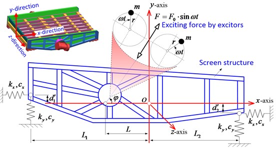
The kinetic energy (denoted by ), the potential energy (denoted by ) and the damping energy (denoted by ) of the system are, respectively:
where is the whole vibration mass of screen structure, is the rotational inertia of the screen structure around -axis. Besides, and are the horizontal distances from the center of mass to the center of parallel compression damping spring system approaching the feeding end and the discharging end, respectively. Meanwhile, and are the vertical distances from the center of mass to the places where springs of the feeding end and the discharge end contact with the screen structure, respectively. It should be noted that when the contact position is opposite to that of the -axis in Fig. 2, a negative value is supposed to be used. and are the transverse stiffness and longitudinal stiffness of parallel compression spring system located in both ends of DELVS, respectively. And and are the transverse damping constant and longitudinal damping constant of parallel compression spring system, respectively.
The Lagrange equations for the coordinates of , , and are, respectively, formulated to be:
where and are the synchronous angular speed of eccentric blocks driven by vibration motors and the magnitude of inertial excitation force, respectively:
where is the distance between inertial excitation force and the center of mass along x-axis direction.
From Eqs. (1) to (6) the dynamic equations have been derived. With a displacement response vector and the corresponding velocity and acceleration response vectors , , dynamic equations for DELVS can be expressed in a matrix form:
where:
are the mass matrix, the damping matrix, the stiffness matrix and the time-dependent dynamic force matrix due to vibration motors, respectively. For a DELVS, vibration response of the screen structure can be obtained by the numerical solution of Eq. (7).
3. Determination of parameters of DELVS
In order to investigate the vibration of a DELVS and verify the feasibility of theoretical analysis above, the parameters of DELVS should be determined. These parameters contain the physical parameters of DELVS and the transverse stiffness of a MCCS.
3.1. Physical parameters
Generally, with a three-dimension geometrical model built and the corresponding materials defined in a three-dimensional modeling software, the center of mass for DELVS can be located accurately, as Fig. 3 shows. Then the physical parameters of DELVS for , , can be gained and reported in Table 1. They are consistent with the parameters of the experimental apparatus which will be presented later.
Fig. 3Physical parameters of DELVS
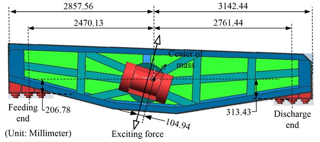
Table 1Physical dimensions and characteristics of DELVS
(kg) | (N·m2) | (kN) | (°) | (rad/s) | (mm) | (mm) | (mm) | (mm) | (mm) |
7814.70 | 19257.27 | 256 | 73 | 104.07 | 2470.13 | 2761.44 | -313.43 | 206.78 | 104.94 |
Furthermore, the damping matrix should be determined as well. For a practical system, due to the various phenomena of energy consumption, it is difficult to construct an accurate damping matrix . Hence, a commonly-used proportional damping method is adopted in this study, which means that the damping matrix is regarded as the linear combination of mass matrix and stiffness matrix, namely [11, 12]:
As the damping ratio needs to be obtained by experiment and has a little influence on the movement under the forced vibration, it is feasible to take the constants and far less than 1, thus, the authors let 0.01 [11].
3.2. Transverse stiffness of a MCCS
Then the stiffness of a MCCS should be determined. It is known that during the working process of DELVS, the oscillated screen structure makes a synchronous dynamic deformation of a MCCS along the transverse and longitudinal direction. Such deformations are both quantifiable on the condition that the transverse stiffness and longitudinal stiffness are available. As the MCCS compression deformation is within 3-7 mm, namely, far less than free length of MCCS and in its linearly-deformed range, the transverse stiffness and longitudinal stiffness are supposed to be a certain constant value [3, 5, 8, 9]. Since the dynamic equation governing DELVS system in Fig. 2 has been illustrated in section 2 and the longitudinal stiffness of a MCCS is well-determined and easily obtained, the key to conducting a numerical simulation of DELVS is to calculate the transverse stiffness . Up to now, there is no uniform method for calculating the transverse stiffness of a MCCS. In this paper, several methods will be compared in the following section.
3.2.1. Direct methods
The direct method of determining of a MCCS is calculating the stiffness value directly by its physical parameters. Here we will introduce the unit-force method and the energy method.
(1) Unit-force method. According to the unit-force method introduced by JENG in [13], the following formula is invoked:
where and are the longitudinal elastic modulus and Poisson ratio of spring material, respectively. is the mean coil diameter of outer spring or inner spring. Similarly, is the wire diameter of spring. is the number of active coil of spring. is the height of spring with the DELVS in a stationary state. Note that the subscript “” denotes the position of spring and “ 1” represents the outer spring while “ 2” represents the inner spring.
As each group of compression damping spring system of DELVS contains three outer and inner MCCSes in a parallel manner, the transverse stiffness of each group of compression damping spring system under the unit-force method is . Here the superscript “uni” means “Unit-force method”.
(2) Energy method. Also, by the energy method introduced by JENG in [13], the transverse stiffness is expressed as:
where is the section moment of inertia of spring wire, is the single circle pitch height of spring. Similarly, the transverse stiffness of each group of compression damping spring system by the energy method is supposed to be . Here the superscript “ene” means “Energy method”.
3.2.2. Indirect methods
As we know, the longitudinal stiffness of a MCCS can be exactly calculated. Therefore, some methods have been developed to obtain the transverse stiffness through the longitudinal one, such as the empirical method as well as the newly-developed elastic compression bar model method (ECBM).
(1) Empirical method. Maybe the empirical method is the most common-used formula for calculating the longitudinal stiffness of a MCCS when designing a vibrating screening. One can find in [6, 12] that the transverse stiffness is regarded as one third of the longitudinal stiffness, i.e.:
where is longitudinal stiffness of a MCCS and can be formulated as [14]:
where is the transversal elastic modulus of the spring. Similarly, the transverse stiffness of each group of compression damping spring system by the empirical method is . Here the superscript “emp” means “Empirical method”.
(2) Elastic compressed bar model method (ECBM). From above we can conclude that the two direct methods are more complex than the empirical method. However, the empirical method was obtained by practical experience and a lack of accurate derivation or sufficient explanation. Here, we will present a simple method.
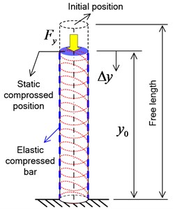
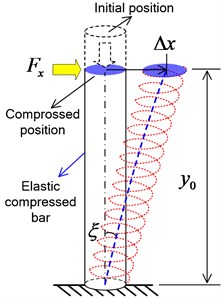
Fig. 4Sketch of the longitudinal deformation: a) and the transverse deformation, b) considered in ECBM
a)
b)
As Yang introduced in [15], a MCCS can be modeled as a compressed straight bar with constant cross-section, whose longitudinal and transverse elastic modulus are the same as those of the MCCS, respectively. The longitudinal deformation of MCCS is equivalent to the compression deformation of modeled bar while the transverse deformation of MCCS is equivalent to the shear deformation of the bar, as depicted in Fig. 4. The static compressed position is where the MCCS remains with the DELVS in a stationary state. The transverse stiffness formula by ECBM will be derived as follows. Note that the derivation is considered in the liner deformation range, which agrees well with the property of practical MCCS of the DELVS.
For a compressed straight bar with constant cross-section, the following relation holds [16]:
where is the longitudinal strain induced by the imposed compress force , and is the cross-section. According to mechanics of materials, if a bar with an initial deformed length (denoted by ) experiences an additional compression deformation (denoted by ) in Fig. 4(a), then we may have:
and furthermore:
where is the longitudinal stiffness.
Also, when a transverse force is applied on the compressed bar, an offset (denoted by ) of the top section occurs, as shown in Fig. 5(b). Assuming that the angle between the initial position and the rotated position of the center line of the compressed bar is in radian, then the shear strain is expressed as . As the shear deformation is so tiny that the angle might represent tan . Thus, we have . For the compressed bar, the shear strain can be expressed as [17]:
and according to the geometrical relationship in Fig. 5(b) and adopt the , we hence obtain:
as well as:
where is the transverse stiffness.
From Eqs. (13) to (18) the transverse stiffness formula by ECBM can be derived to be:
where is longitudinal stiffness, as Eq. (12) demonstrates. Here the superscript “ECBM” means “Elastic compressed bar model method”. Similarly, the transverse stiffness of the damping spring system by ECBM is .
Table 2Physical parameters of MCCS of DELVS
Symbols (Unit) | (GPa) | (GPa) | (m) | (m) | (m) | (m) | ||
Outer spring | 79 | 206 | 0.03 | 6 | 0.193 | 0.2909 | 0.3 | 0.05 |
Inner spring | 79 | 206 | 0.02 | 7 | 0.115 | 0.2009 | 0.3 | 0.03 |
Based on the basic parameters of the experimental MCCS in Table 2, the transverse stiffness and longitudinal stiffness of the inner and outer MCCS are calculated according to the four stiffness calculation methods, as shown and compared in Table 3. The transverse stiffness values obtained by the four methods are entirely different. Among them, the value by the proposed ECBM method is the largest for both the inner spring and outer spring. Currently, we are hard to distinguish which method matches better well with the actual situation and which method is more fit for DELVS.
Table 3Transverse and longitudinal stiffness value of the MCCS in the experimental apparatus
Symbols (Unit) | Method | Outer spring ( 1) | Inner spring ( 2) |
(N/m) | NONE | 1.8544×10⁵ | 1.4841×10⁵ |
(N/m) | Unit force method | 6.0701×10⁴ | 3.7364×10⁴ |
Energy method | 5.7506×10⁴ | 3.4476×10⁴ | |
Empirical method | 6.1813×10⁴ | 4.9470×10⁴ | |
ECBM method | 7.1115×10⁴ | 5.6915×10⁴ |
4. Model validation
Next, dynamic model of DELVS together with the proposed ECBM will be validated through numerical simulation and the experimental test. And then a relatively feasible transverse stiffness determination method for DELVS will be determined.
4.1. Numerical solution
The complete numerical simulation procedure is illustrated in the flowchart in Fig. 5. For a DELVS, vibration response of the screen structure can be obtained by the numerical solution of Eq. (7), which can be solved by a numerical direct time-integration method such as the Newmark- method [18, 19]. It is widely used in the numerical evaluation of the dynamic response of structures. Here Matlab was used to conduct the numerical simulation with the Newmark- method. In the simulation, the zero initial displacement, the zero initial velocity and the zero acceleration of DELVS are considered. Each transverse stiffness calculation method for a MCCS in section 2.2 will be adopted in order to demonstrate the theoretical vibration response. Note that the numerical stability of Newmark- scheme can be guaranteed when 0.5, 0.25 [18]. In this paper, we set 0.5 and 0.25. In addition, as the sampling frequency of the experimental test is 10.24 kHz, we make the time interval 1/10240 s. Other parameter is simulation time 60 s.
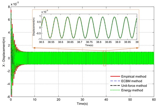
Fig. 6 indicates the numerical solution result of the DELVS. The transverse time responses (-displacement) with the Empirical method, the ECBM method, the Unit-force method and the Energy method are compared. From the whole time response, it is seen that the transverse motion all trend to stability at an amplitude of nearly 1.0 mm. Even in the local magnification curve of the response between 38.5 s and 39.0 s, there is no any significant difference. Thus, we can conclude that the transverse stiffness is not easy to affect the transverse time response.
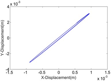
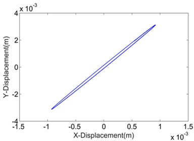
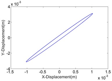
Fig. 7 shows and compares the Lissajous curves indicating the relationship between the numerical transverse displacement and longitudinal displacement. These curves are, in fact, the numerical vibration trajectories of the DELVS by various transverse stiffness calculation methods. All the trajectories are adjusted according to the same scale for an intuitional demonstration. With the influence of rotation around -direction in Fig. 2, the trajectories are more like slender ellipses than straight lines. Additionally, for the ECBM method, the ellipse has a larger minor axis than the others, which implies that a large stiffness may affect the trajectory of the DELVS.
Fig. 5Flowchart of the numerical solution for DELVS
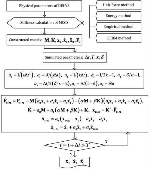
Fig. 6Numerical transverse time response of the DELVS by various transverse stiffness calculation methods
4.2. Experimental test
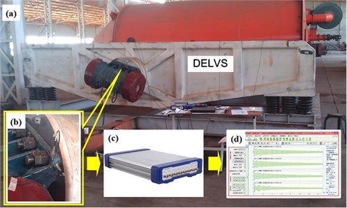
The experimental system and equipment are shown in Fig. 8. Two same types of acceleration sensors (measurement range is 500 m/s2, resolution ratio is 0.002 m/s2, frequency range is 0.5-8 KHz) are magnetically attached on the vibration motor support of DELVS for obtaining the transverse and longitudinal vibration signal, respectively. These sensors are connected with a data acquisition instrument, and then signals can be collected and handled through a data acquisition software. During the experimental test, the vibration signal of each measuring point was acquired simultaneously, and only the steady-state signal was used. After obtaining the data, the software DASP (China Orient Institute of Noise & Vibration, China) was utilized for data processing.
Fig. 7Numerical vibration trajectories of DELVS by various transverse stiffness calculation methods
a) Uni-force method
b) Energy method
c) Empirical method
d) ECBM method
Fig. 8Experimental apparatus: a) experimental DELVS; b) displacement sensors; c) data acquisition instrument; d) data acquisition software
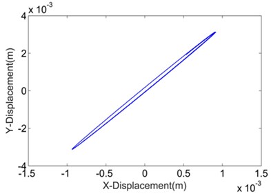
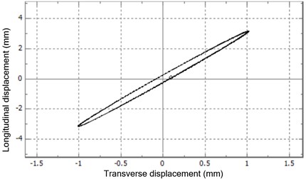
The measured acceleration signals were digitally filtered with a cutoff of 100 Hz and analyzed by numerical integration so that the experimental transverse displacement and longitudinal displacement were extracted, as viewed in Fig. 9. Note that the corresponding Lissajous curve was generated by the data acquisition software automatically. The magnitude of longitudinal displacement is larger than that of transverse displacement, for the reason that the vertical component force is larger than the horizontal component force. Besides, displacements in the two directions share the same frequency and phase. Rotation exists in the experimental DELVS as the vibration trajectory of DELVS is a slender ellipse, and the experimental ellipse is more like the numerical ellipse by ECBM.
Fig. 9Experimental transverse displacement: a) longitudinal displacement, b) the corresponding Lissajous curve

a)
b)
4.3. Numerical solution vs. experimental test
In view of quantification, the kinematic characteristics of DELVS, i.e., the transverse amplitude (denoted by ), the longitudinal amplitude (denoted by ), the compound amplitude (denoted by ) and the vibration angle (denoted by ) are listed in Table 4, among which according to the test methods of vibrating screens, we have and [20].
Table 4Movement characteristics of DELVS
Parameters (Unit) | Numerical results | Experimental results | |||
Empirical method | Unit-force method | Energy method | ECBM | ||
(mm) | 3.126 | 3.126 | 3.126 | 3.126 | 3.1897 |
(mm) | 0.9195 | 0.9134 | 0.9468 | 1.026 | 1.0218 |
(mm) | 3.2584 | 3.2567 | 3.2662 | 3.2901 | 3.3494 |
(°) | 73.6090 | 73.7119 | 73.1495 | 71.8294 | 72.2375 |
Here the values of transverse amplitude and longitudinal amplitude were acquired from time history in the stable operation. We can find that although the transverse stiffness values by the corresponding calculation method are different, the numerical vibration characteristics are almost the same as those of the experiment, which verifies the 3-DOF theoretical model of DELVS and confirms the derivation in Section 2. However, it is still hard to distinguish which transverse stiffness calculation method is the best in view of transverse stiffness value itself. Fortunately, since the errors of the numerical simulation data by ECBM are 0.41 % for , –1.77 % for , and –0.56 % for , respectively, and are more closely related to the experimental data, ECBM is verified to improve the accuracy of DELVS dynamic model successfully. It should be noted that as a vibrating screen works in the super-resonant mode, the stiffness of MCCS has little influence on the movement characteristics of the screen structure. However, as the two vibration motors with eccentric blocks inside are mounted on the left and right lateral plate for a DELVS, respectively, the screen structure is easier to experience a lateral oscillation than a traditional vibrating screen. In order to further study such lateral oscillation, a more accurate calculation method for the transverse and longitudinal stiffness of a MCCS, such as the proposed ECBM method, is necessary.
5. Conclusions
The proposed 3-DOF dynamic model as well as the theoretical analysis of DELVS is verified as the numerical vibration characteristics are almost the same as those of the experiment. From the numerical simulation result by Newmark- method, the transverse stiffness is not easy to affect the transverse time response despite the entirely different transverse stiffness values obtained by the four methods. However, the numerical simulation data of the proposed ECBM are in better agreement with the experimental data, which means that ECBM can improve the accuracy of DELVS dynamic model.
References
-
Noble A., Luttrell G. H. A review of state-of-the-art processing operations in coal preparation. International Journal of Mining Science and Technology, Vol. 25, Issue 4, 2015, p. 511-521.
-
Makinde O. A., Ramatsetse B. I., Mpofu K. Review of vibrating screen development trends: Linking the past and the future in mining machinery industries. International Journal of Mineral Processing, Vol. 145, 2015, p. 17-22.
-
Zhang Z. R. Strain modal analysis and fatigue residual life prediction of vibrating screen beam. Journal of Measurements in Engineering, Vol. 4, Issue 4, 2016, p. 217-223.
-
Jiang H., Zhao Y., Duan C., et al. Kinematics of variable-amplitude screen and analysis of particle behavior during the process of coal screening. Powder Technology, Vol. 306, 2017, p. 88-95.
-
Jiang H, Zhao Y, Duan C, et al. Dynamic characteristics of an equal-thickness screen with a variable amplitude and screening analysis. Powder Technology, Vol. 311, 2017, p. 239-246.
-
Despotović Ž. V., Pavlović A., Radaković J. Regulated drive of vibratory screens with unbalanced motors. Proceedings of 15th International Scientific-Professional Symposium Infoteh-Jahorina, Vol. 15, 2016, p. 155-160.
-
Baragetti S., Villa F. A dynamic optimization theoretical method for heavy loaded vibrating screens. Nonlinear Dynamics, Vol. 78, Issue 1, 2014, p. 609-627.
-
Baragetti S. Innovative structural solution for heavy loaded vibrating screens. Minerals Engineering, Vol. 84, 2015, p. 15-26.
-
Peng L. P., Liu C. S., Li J., et al. Static-deformation based fault diagnosis for damping spring of large vibrating screen. Journal of Central South University, Vol. 21, Issue 4, 2014, p. 1313-1321.
-
Michalczyk J., Bednarski Ł., Gajowy M. Feed material influence on the dynamics of the suspended screen at its steady state operation and transient states. Archives of Mining Sciences, Vol. 62, Issue 1, 2017, p. 145-161.
-
Wang B. T., Cheng D. K. Modal analysis by free vibration response only for discrete and continuous systems. Journal of Sound and Vibration, Vol. 330, Issue 16, 2011, p. 3913-3929.
-
Du C., Gao K., Li J., et al. Dynamics behavior research on variable linear vibration screen with flexible screen face. Advances in Mechanical Engineering, Vol. 6, 2014, p. 243-254.
-
Jeng J. W. Experimental Study of a Full-Scale Vibration Isolated Mechanical/Electrical Equipment. Master’s thesis. National Taiwan University of Science and Technology, Taipei, 2011.
-
DIN EN 13906-1:2002. Cylindrical Helical Springs Made from Round Wire and Bars-Calculation and Design-Part 1: Compression Springs.
-
Yang G., Xiao S., Zhang W. Analysis on the lateral stiffness of the helical circle spring. Zhongguo Tiedao Kexue, Vol. 31, Issue 4, 2010, p. 59-62.
-
Beer F., Johnston R., DeWolf J., Mazurek D. Mechanics of Materials. 7th Edition, McGraw-Hill, New York, 2014.
-
Filippi M., Carrera E., Zenkour A. M. Static analyses of FGM beams by various theories and finite elements. Composites Part B: Engineering, Vol. 72, 2015, p. 1-9.
-
Iwata Y., Komatsuzaki T., Kitayama S., et al. Study on optimal impact damper using collision of vibrators. Journal of Sound and Vibration, Vol. 361, 2016, p. 66-77.
-
Lee H. J., Schiesser W. E. Ordinary and Partial Differential Equation Routines in C, C++, Fortran, Java, Maple, and MATLAB. Chapman & Hall/CRC, London, 2004.
-
JB/T 4042-2008. Test methods of vibrating screens, (in Chinese).
Cited by
About this article
This work is supported by the National Natural Science Foundation of China (Grant No. 51605138), the Found of State Key Laboratory of Mineral Processing (BGRIMM-KJSKL-2016-04), the Natural Science Foundation of Jiangsu Province (Grant No. BK20160286), the Project funded by China Postdoctoral Science Foundation (Grant No. 2016M590514) and the Changzhou Sci and Tech Program (Grant No. CJ20179022).
Liping Peng proposed the dynamic model and ECBM method for DELVS. Runxin Fang conducted the experimental test. Huihui Feng done the numerical simulation of DELVS. Lei Zhang designing the experiment. Wenda Ma analyzed the experimental data. Xiaodi He build the three-dimension geometrical for DELVS.
