Abstract
Aiming at the shortcomings of traditional vibrating screens with large vibration mass, a double eccentric cam self-synchronous vibrating screen is proposed. The motion differential equation of the vibrating screen system is derived by using Lagrange equation and the steady state solution is obtained. According to Hamilton principle, the synchronization condition of the vibration system is deduced, and the stability condition of the self-synchronization motion is obtained. The influencing factors of synchronization and stability are investigated by using numerical calculation and simulation analysis methods. The results show that stable self-synchronous motion of the vibration system is implemented when the synchronization and stability conditions are satisfied; the value of the stable phase difference of two cams varies in the range of (–1.5 rad, 0), and compared with the residual torque difference, the eccentricity of eccentric cams has a greater impact on the stable phase difference; additionally, a linear motion track of the vibrating screen is achieved.
Highlights
- A new type of double cam self-synchronous vibrating screen with low vibration mass is proposed.
- The dynamic model is established and the synchronization and stability conditions of the vibrating system are derived.
- The self-synchronous motion characteristics are studied by numerical calculation and simulation analysis under different conditions.
- The motion track is straight, easy to achieve large amplitude and low energy consumption.
1. Introduction
The drilling vibrating screen is the primary solids control equipment for drilling fluid circulation. Its purpose is to fully recover the drilling fluid and remove as many solid particles as possible. Synchronous vibrating screens have been widely used in mining, metallurgy, petroleum and other industries, due to their simple structure and high efficiency [1, 2]. Blekhman [3] first proposed the synchronization theory of mechanical exciters in the 1950s. Since then, self synchronization theory has been introduced into many vibrating machines excited by two eccentric rotors. Zhao [4] described the synchronous behavior of the vibrating system with a dual-rotor system based on the concept of generalized synchronization. Through numerical and experimental research [5], researchers found that two eccentric rotors can synchronize in-phase or anti-phase under different conditions. For improving the exciting force, they applied different methods to achieve synchronous vibration of dual-rotor systems.
Besides, numerous scientists have been doing extensive research on the synchronization of multi-rotor system [6-8]. Zhang [9] investigated the synchronization of three non-identical coupled exciters rotating with the same directions in a far-resonant vibrating system of plane motion. Kong [10] investigated the composite synchronization of four eccentric rotors driven by induction motors in a vibration system, and the numerical simulation and some experiments are employed to confirm the feasibility of the composite synchronization method. Overall, to obtain great exciting force, they generally drive the multi-rotor system synchronized by self-synchronization, coupling synchronization, composite synchronization and other methods. As the number of rotors or exciters rises, the vibration mass increases. In addition, with the development of vibrating screen, industries seem to be inclining towards larger or multilayer screens to reduce production costs [11]. The vibration mass increases with the increase of screen layers. Hence, for traditional vibrating screens, it is often necessary to increase the mass of the eccentric rotors or the power of the exciter to obtain greater exciting force, which will limit the screening capacity and screening efficiency of the vibrating screen.
A lot of research on other forms of vibration machinery with low vibration mass has been published. Ran et al. [12] studied a double crank and connecting rod (CCR) vibrating screen, which can realize the translational circular motion of the vibrating screen connected with the CCR. The CCR mechanism can effectively reduce the vibration mass and realize reciprocating motion. But due to a large number of joints and taking up lots of space, it is easily damaged with large friction and inertial impact. The clearance faults on joint of moving mechanism are most common in CCR mechanism [13, 14]. At present, the cam mechanism is also frequently used to implement reciprocating motion. As long as the contour curve of the cam is appropriately designed, the required motion law can be accurately achieved [15, 16]. Xiao et al. [17] utilized the irregular movement of the cam to simulate the principle of manual screening and proposed a new type of double cam vibrating screen, improving the screening efficiency. The obvious advantages of the cam-type vibrating screen are compact structure and low vibration mass, avoiding the shortcomings of the CCR mechanism with many components. Meanwhile, the cam mechanism is also widely used in various automatic machinery, instruments and manipulation control devices [18-20]. However, rigid (gear) or flexible (belt, chain) transmission is always used to achieve synchronous motion in the various machines [21-22]. There is little research on the self-synchronization movement, especially the self-synchronization of cam-type vibrating screen. Consequently, a new type of double cam-driven self-synchronous vibrating screen has been proposed in this paper. The self-synchronization and stability conditions of the vibrating screen system are studied. Through numerical calculations and simulation analyses which are performed by Matlab/Simulink, the factors affecting synchronization characteristics and stability of the system are investigated.
2. Dynamic model
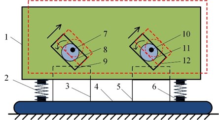
The double eccentric cam self-synchronous vibrating screen is mainly composed of cams, camshafts, cam grooves, screen frame and so on, as shown in Fig. 1. The two motors are respectively installed on the motor seats which are fixed on the base. The camshaft is supported by a bearing seat installed on the base, the motor shaft is connected with the camshaft, and the cam is placed in a rectangular cam groove on the screen frame, which is tangent to the two long sides of cam groove, while maintaining a proper gap with the short sides. The screen frame is supported by damping springs. In the working process of the vibrating screen, the motor rotors running synchronously drive two camshafts to rotate synchronously, respectively, thus driving the eccentric cams to rotate around their respective camshafts. According to the geometric constraints of the cam mechanism, the rotation of eccentric cam can be converted into the reciprocating linear uniform motion of the follower (cam groove). Therefore, the new vibrating screen converts the synchronous rotation motion of the two eccentric cams into the vibration of the screen frame through the cam mechanism, so as to realize the vibration synchronous transmission of the system.
Fig. 1A motion diagram of the vibrating screen: 1 – screen frame, 2 – damping spring, 3 – motor seat 1, 4 – base, 5 – motor seat 2, 6 – spring support, 7 – camshaft 1, 8 – cam 1, 9 – cam groove 1, 10 – camshaft 2, 11 – cam 2, 12 – cam groove 2
The friction and contact point are constantly changing during the rotation, so that the direction of the resultant force does not always point to the mass center of the screen frame, which result in a swing motion.
The following assumptions were made when establishing the dynamic model:
(1) The rotation centers of two cams are at the same distance from the mass center and the three centers are on a straight line.
(2) The cam and cam groove are rigid components which are always in full contact [23].
(3) The damping of between cam and cam groove is equivalent to the friction coefficient .
(4) The inertial force generated by cam rotation is eliminated by setting the counterweight on the camshaft.
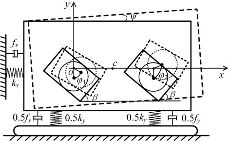
Taking the rotation center o of cam 1 as the coordinate origin, the rectangular coordinate system shown in Fig. 2 is established. The screen frame reciprocates in the - and - directions and rotates in the - direction, so there are three degrees of freedom in the system. The two cams respectively rotate around their own rotation axis, and their positions can be determined by the parameters and .
According to the geometric constraint, the displacement response of the mass center in the - and - directions can be obtained, which relates to the parameters , and . The displacement response is shown as:
where is the dip angle of the cam groove in the vertical direction; is angular displacement of the screen frame around its mass center in plane ; and are the angular displacements of the cams rotation, respectively; is the contour radius of the eccentric cam; is the eccentricity of the eccentric cams.
Fig. 2The dynamic model of the double cam vibration system
According to the dynamic theory and the physical model, the total kinetic energy of the vibrating model is obtained by:
where (kg) is the mass of the screen frame; (kg·m2) is the rotational inertia of the screen frame with respect to its mass center; (kg·m2) is the rotational inertia of the -th cam (including camshaft and motor shaft), 1, 2; is the generalized coordinate of the system; is the generalized force of the system; and denote and , respectively.
Meanwhile, the total potential energy of the vibrating system can be written as:
where , (N/m) are the stiffness coefficients of the damping spring in the - and -directions, respectively; (N·m/rad) is the stiffness coefficients in the -direction.
Furthermore, the whole dissipated energy of the vibrating model is described as:
where , (N·s/m) are the damping coefficient of the screen frame in - and -directions, respectively; (N·m·s/rad) is the damping coefficient in -direction; (N·m·s/rad) is the damping coefficient of the -th cam in its rotation direction; is the friction coefficient.
Finally, dynamic equations of the system can be determined by Lagrange equation:
Considering the generalized coordinate matrix is in the vibrating system, the generalized force matrix is established as , where and are the electromagnetic torque of the -th motor and the friction torque on the -th motor shaft, respectively. Since has a smaller value than , and , the value of can be ignored when calculating the trigonometric function of (), (). When two identical motors are running stably, the asymmetry and damping caused by the system can also be ignored. Assuming that the stiffness and damping of the damping spring in the - and -directions are the same, which , . After arranging, the final dynamic equations of the vibration system can be expressed as:
where Eqs. (1-2, 7-9) constitute the dynamic differential equations of the double cam vibrating system.
3. Synchronization theory
In light of the literature [24], it should be noted that with respect to a periodic function of time is a slowly varying parameter. Due to the periodic motion of the vibrating system, the velocity of two motors also changes periodically. Assigning the least positive period of two motors as , in which their average velocity over a period of time is approximately equal to a constant, so it can be expressed as:
The phase of cam 1 is ahead of the phase 2 of cam 2, thus:
In order to simplify the calculation process, we have ignored the effect of some nonlinear terms. Eq. (7) can be transformed into:
Performing Laplace transform on Eq. (12), the steady displacement response of -direction can be obtained by:
where:
Substituting Eq. (13) into Eqs. (1-2), the steady responses of displacement in - and -direction are obtained.
In addition to gravity, the vibrating system is only affected by the electromagnetic torque and the friction torque which is on the cam shafts. According to the principle of Hamilton:
The Hamiltonian action in a motion cycle is derived as:
where, is the sum of the rotational kinetic energy of the two eccentric cams, which can be regarded as a constant when the motors are running stably.
Derivative and simplify Eq. (15), then get:
The generalized force is described as:
Substituting Eqs. (16) and (17) into Eq. (14), the balance equation can be obtained as:
Considering Eq. (18), the condition for the existence of real solutions is the self-synchronization condition. In order to ensure the existence of the solution to , the absolute value of is not allowed to be greater than 1. Thus, the self-synchronization condition is described as:
where is the residual torque difference of the two motors, and:
The stability condition of the vibration system is analyzed based on three principles, which are the stability discrimination of the multivariate function system, the extreme value theory of the function and that Hamiltonian action has an extreme value, respectively. In the restraint system, the Hamiltonian action of real motion has a minimum value. Therefore, the stability condition of the vibration system is expressed as:
which is:
4. Numerical analysis
In order to verify the correctness of the above derivations, numerical analysis and simulation were carried out with Matlab. From Eqs. (21-22), it can be seen that the self-synchronous stable state is may determined by these independent parameters: the eccentricity, the radius of eccentric cam, the mass of screen frame, the stiffness of springs, the residual torque difference and other parameters.
The estimation error of unknown quantity can be reduced through the understanding of known quantity with the controlling variable method, that is, only one of the factors is changed each time, while the remaining factors remain unchanged, so as to study the influence of the changed factor on things, conduct separate studies, and finally solve the problem comprehensively. Therefore, to judge the influence of relevant parameters on the synchronization state more accurately, the controlling variable method is used to discuss the influence of the eccentric cam eccentricity and the residual torque difference respectively.
Table 1System simulation parameters
Cams | Motors | Screen frame | Damping springs |
0.002-0.004 (m) | 157 (rad/s) | 126 (kg) | 250,000 (N/m) |
0.04 (m) | 0.01 (N⋅m⋅s/rad) | 10 (kg⋅m2) | 250,000 (N⋅m/rad) |
0.1 | 0.02 (kg⋅m2) | 0.25 (rad) | 1,000 (N⋅s/m) |
0-5 (N⋅m) | – | – | 1,000 (N⋅m⋅s/rad) |
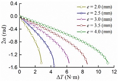
The accurate description of the movement process can be made by selecting system parameters reasonably. Performing numerical simulation analysis according to some system parameters given in Table 1. The relationship between the cam eccentricity and the stable phase difference 2 is shown in Fig. 3, considering the residual torque difference is equal to 0, 1, 2, 3, 4, 5 [N·m], respectively; the relationship between the residual torque difference and the stable phase difference 2 is shown in Fig. 4, when the cam eccentricity is equal to 2, 2.5, 3, 3.5, 4 [mm], respectively.
As shown in Fig. 3, while the value of residual torque difference is constant, the value of stable phase difference decreases with the increase of the eccentricity; when the eccentricity is constant, the greater the residual torque difference, the larger the stable phase difference; if the eccentricity exceeds 11 [mm], the value of the phase difference remains unchanged at 0 [rad]. Therefore, the eccentricity should be large enough, otherwise the synchronous state of zero phase difference is difficult to achieve; the smaller the residual torque difference, the wider the adjustable range of the eccentricity.
As demonstrated in Fig. 4, when the eccentricity is determined, the stable phase difference increases with the increase of the residual torque difference. The value of the stable phase difference gradually decreases from 0 [rad] to –1.5 [rad]. If the residual torque difference continues to increase, the self-synchronization conditions cannot be satisfied, so that the synchronous state cannot be achieved; the smaller the eccentricity, the greater the influence of the residual torque difference on the synchronous state. In order to satisfy the self-synchronization and stability conditions, the residual torque difference must be small enough. Additionally, a reasonable adjustment of the eccentricity can make the phase difference meet the actual needs.
As shown in Fig. 3, once the eccentricity exceeds a certain value, the phase difference tends to remain constant and the increase of the residual torque difference will not cause the phase difference to change. As shown in Fig. 4, the smaller the eccentricity, the faster the curve falls. Therefore, it is not difficult to find that the eccentricity has a greater influence on the stable phase difference. The eccentricity should be large enough, otherwise it is difficult to adjust the stable phase difference. In engineering applications, it is better to force the stable phase difference to be close to the ideal value firstly by adjusting the eccentricity, and then regulating the residual torque difference to make the stable phase difference achieve the ideal value.
Fig. 3The relationship between the eccentricity e and the stable phase difference 2α
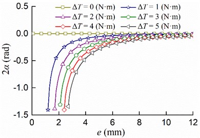
Fig. 4The relationship between the residual torque difference ∆T and the stable phase difference 2α
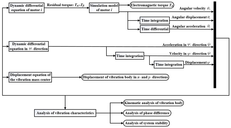
5. Simulation analysis
Runge-Kutta algorithm ode45 and adaptive step size control are used for simulation, the schematic diagram of the flow chart of the simulation model, as shown in the Fig. 5.
Assuming relevant simulation parameters according to Table 1, where 3 [mm], 0.25 [rad], and selecting two same motors (0), the numerical analysis results show that the value of the stable phase difference is near 0 [rad]. The synchronous motion under various conditions was simulated to verify the correctness of the theoretical analysis.
Fig. 5Schematic diagram of the simulation
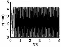
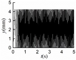
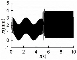
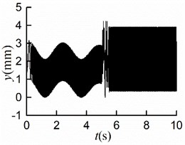
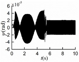
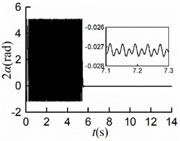
5.1. Two rotors rotate counterclockwise simultaneously with same initial phase 0
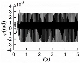
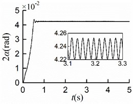
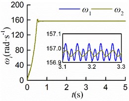
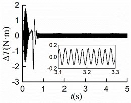
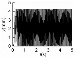
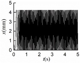
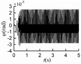
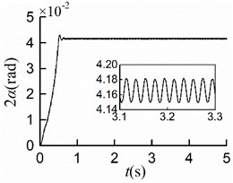
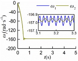
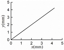
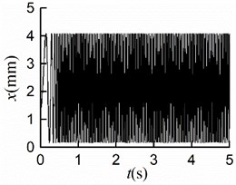
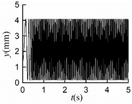
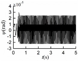
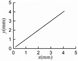
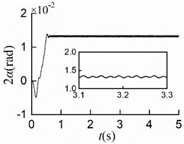
The simulation results are shown in Fig. 6. The stable synchronous state of the system is implemented around 0.9 s. From Figs. 6(a, b), it can be seen that the displacements of the mass center in - and -directions are identical where the maximum displacement is 4.2 [mm]. Thus, the vibration trajectory is a straight line, and the centroid amplitude is equal to 3.0 [mm] which is the same as the eccentricity. As shown in Fig. 6(c), the maximum angular displacement in the stable synchronous state is 2.5×10⁻⁵ [rad], which indicates that the impact of swing can be neglected; As demonstrated in Fig. 6(d), the value of the stable phase difference is stabilized to 0.04 [rad] (= 2.29°); As is shown in Fig. 6(e) the steady velocities of motors are close to 157 [rad/s]; As revealed in Fig. 6(f), two rotors are with similar residual torque. The dynamics characteristics of the system obtained by simulations are in line with the numerical analysis results.
Fig. 6Simulation results of counterclockwise rotation
a)
b)
c)
d)
e)
f)
5.2. Two rotors rotate clockwise simultaneously with same initial phase 0
With other simulation parameters identical, the simulation results of rotating clockwise are shown in Fig. 7. The simulation results of displacements are the same as those in section 5.1, as shown in Figs. 7(a, b, c, f). As displayed in Fig. 7(d), the value of the stable phase difference is stabilized to 0.04 [rad] (= 2.29°), which is identical to that of counterclockwise rotation; The rotors rotate counterclockwise, and the steady velocities of motors are nearly 157 [rad/s] as shown in Fig. 7(e). The process of synchronous motion is identical to that of clockwise rotation. Therefore, the rotation direction of the rotors has no effect on the synchronous state.
Fig. 7Simulation results of clockwise rotation
a)
b)
c)
d)
e)
f)
5.3. Two rotors rotate simultaneously with different initial phases
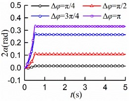
The two rotors are not necessarily in an ideal state with the same initial phase. Other simulation parameters were kept unchanged, the value of the initial phase difference was selected to be , , , [rad], respectively, where the initial phase of rotor 2 is 0 [rad].
Considering , the simulation results are shown in Fig. 8(a, b, c, d, e). The synchronous state is implemented at the same time with different initial. Displayed in Fig. 8(a, b), the maximum displacement of the mass center in -direction is 4.1 [mm], so is that in -direction. Owing to the different initial phases, there was a certain skew of the screen frame before operating, which resulted in the minimum displacements in - and -directions are neither 0 [mm]. It is not difficult to recognize that the amplitude of the mass center is 2.89 [mm]. As shown in Fig. 8(e), the stable phase difference with the value of 1.3×10⁻² [rad].
Comparing Fig. 8(f) with Fig. 6-7(e), the larger the initial phase difference, the greater the value of the stable phase difference. Thence, the initial phase difference should be adjusted reasonably to control the phase difference with the variation range (0.04, 0.34) [rad].
5.4. Two rotors start non-simultaneously with different initial phases
In order to research the influence of the different starting states on the synchronization further, the rotor 1 was operated when the rotor 2 had run for 5 seconds.
Fig. 8Simulation results of different initial phases
a)
b)
c)
d)
e)
f)
Fig. 9Simulation results of starting at different time
a)
b)
c)
d)
e)
f)
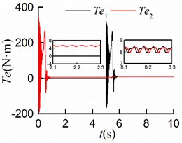
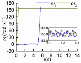
As shown in Figs. 9(a, b, c), the steady displacements of the mass center in the three directions , , are identical to those in the condition of simultaneous startup, respectively. From Fig. 9(d), it can be seen that the stable phase difference is –0.03 [rad] (= 1.72°), which matches the numerical analysis results. As displayed in Figs. 9(e, f), the steady velocities of motors are around 157 [rad/s]. Once the rotors rotated at the same speed with similar electromagnetic torque, the stable self-synchronous state of the vibration system can be implemented.
6. Conclusions
On the base of the theoretical research and numerical analysis, the following conclusions are obtained.
1) A double eccentric cam self-synchronization vibration system is proposed. Lagrange equation is used to derive the dynamic differential equation of the system, steady state solution has been obtained. The synchronization condition and stability condition have been investigated, which are and , respectively.
2) The self-synchronous motion with stable phase difference can be implemented, where the value of the stable phase difference varies in the range of (–1.5, 0) [rad] by adjusting the eccentricity of the cams and the residual torque difference of the motors. The influence of the system parameters on synchronization is mainly manifested as the influence on the stable phase difference, where the eccentricity has a larger effect on the stable phase difference.
3) The stable synchronous state of the vibrating system can be implemented, no matter the two identical motors with different initial phases start simultaneously or non-simultaneously. Moreover, the stable phase difference can be regulated in the variation range of (0.04, 0.34) [rad] for different initial phases, where the motion states are consistent. The rotation direction of the motors does not affect the synchronous state of the system. The angular displacement of the vibrating screen is extremely small; thus, the impact of swing can be neglected. In addition, the linear reciprocating motion of the vibrating screen can be achieved, and the amplitude can be designed since it is identical to the eccentricity of the eccentric cams.
4) The validity of the used theory method and the correctness of the obtained results for the self-synchronization of double cam vibration system, are verified to be feasible by the analyses of the theories, numerical qualitative analyses and simulations.
References
-
Wen B. C., Zhang H., Liu S. Y., et al. Theory and Techniques of Vibrating Machinery and Their Applications. Science Press, Beijing, 2010.
-
Wen B. C., Fan J., Zhao C. Y. Synchronization and Controled Sychronization in Engineering. Science Press, Beijing, 2009.
-
Blekhman I. I. Synchronization in Science and Technology. ASME Press, 1988.
-
Zhao C. Y., Zhang Y. M., Wen B. C. Synchronisation and general dynamic symmetry of a vibrating system with two exciters rotating in opposite directions. Chinese Physics B, Vol. 19, Issue 3, 2010, p. 301-308.
-
Boris A., Alexander L. F., Olga P. T., et al. Angular velocity and phase shift control of mechatronic vibrational setup. IFAC-PapersOnline, Vol. 52, Issue 15, 2019, p. 436-441.
-
Zhang X. L., Wen B. C., Zhao C. Y. Synchronization of three homodromy coupled exciters in a non-resonant vibrating system of plane motion. Acta Mechanica Sinica, Vol. 28, Issue 5, 2012, p. 1424-1435.
-
Zhao C. Y., Wen B. C., Zhang X. L. Synchronization theory of multi-type self-synchronous vibration system. Science China Technological Sciences, Vol. 53, Issue 2, 2010, p. 405-422.
-
Zhang N., Hou X. L., Wen B. C. The synchronism theory of three motor self-synchronism exciting elliptical motion shaker. Journal of China Mechanical Engineering, Vol. 5, Issue 15, 2009, p. 1838-1844, (in Chinese).
-
Zhang X. L., Wen B. C., Zhao C. Y. Synchronization of three non-identical coupled exciters with the same rotating directions in a far-resonant vibrating system. Journal of Sound and Vibration, Vol. 332, Issue 9, 2013, p. 2300-2317.
-
Kong X. X., Wen B. C. Composite synchronization of a four eccentric rotors driven vibration system with a mass-spring rigid base. Journal of Sound and Vibration, Vol. 427, Issue 8, 2018, p. 63-81.
-
Makinde O. A., Ramatsetse B. I., Mpofu K. Review of vibrating screen development trends: Linking the past and the future in mining machinery industries. International Journal of Mineral Processing, Vol. 145, Issue 4, 2015, p. 17-22.
-
Jiao N., Zhang L., Zhang L. Unit design and motion simulation of crank group driving mechanism. Journal of Mechanical Transmission, Vol. 2, Issue 2, 2014, p. 86-89, (in Chinese).
-
Xiao Q. F., Liu S. L., Nie A., et al. Dynamic analysis of the moving mechanism of the reciprocating compressor with clearance joints. Vibroengineering Procedia, Vol. 19, 2018, p. 76-81.
-
Grigore J. C. The methods to study the influence of the clearance in the case of great speeds and small speeds. Advanced Materials Research, Vol. 2845, Issue 5, 2014, p. 88-92.
-
Hejma P., Svoboda M., Kampo J., et al. Analytic analysis of a cam mechanism. Procedia Engineering, Vol. 177, 2017, p. 3-10.
-
Tao J., Wang G., Li J. Structural design and simulation of passive low gravity compensation for the deployable arm in the device of drilling and collecting lunar soil. International Conference on Engineering Technology and Application, Xiamen, 2015.
-
Xiao J. Z., Tong X. Characteristics and efficiency of a new vibrating screen with a swing trace. Particuology, Vol. 11, Issue 5, 2013, p. 601-606.
-
Lee G., Lee D., Oh Y. One-piece gravity compensation mechanism using cam mechanism and compression spring. International Journal of Precision Engineering and Manufacturing-Green Technology, Vol. 5, Issue 3, 2018, p. 415-420.
-
Liu Y., Yu D. P., Yao J. Design of an adjustable cam based constant force mechanism. Mechanism and Machine Theory, Vol. 103, 2016, p. 85-97.
-
Jeremiah S. S., Joel C. P. Development of a series wrapping cam mechanism for energy transfer in wearable arm support applications. International Conference on Rehabilitation Robotics, Vol. 2017, 2017, p. 585-590.
-
Quaglia G., Nisi M. Design of a self-leveling cam mechanism for a stair climbing wheelchair. Mechanism and Machine Theory, Vol. 112, 2017, p. 84-104.
-
Ning Y., Xu W., Huang H., et al. Design methodology of a novel variable stiffness actuator based on antagonistic-driven mechanism. Proceedings of the Institution of Mechanical Engineers, Part C: Journal of Mechanical Engineering Science, Vol. 233, Issues 19-20, 2019, p. 6967-6984.
-
Jin G. G., Wei, Qin K. X., et al. Dynamic analysis and modal truncation of high-speed cam mechanism. Chinese Journal of Mechanical Engineering, Vol. 51, Issue 13, 2015, p. 227-234, (in Chinese)
-
Zhao C., Zhu H., Wang R., et al. Synchronization of two non-identical coupled exciters in a non-resonant vibrating system of linear motion. Shock and Vibration, Vol. 16, Issue 5, 2008, p. 49-60.
About this article

This study is supported by supported by National Natural Science Foundation of China Youth Fund (Grant No. 51705437) and Sichuan Science and Technology Program (2019YFG0317).
