Abstract
Synchronization of two exciters with asymmetric structure is more widely used in engineering, such as vibrating conveyer, dewatering screen, vibrating screen, however, the synchronization state of two exciters with asymmetric structure in the sub-resonant and super-resonant states is less considered, and it is a valuable research topic. Firstly, we establish a kind of weakly nonlinear vibrating system driven by two exciters with opposite rotation directions and asymmetrical structure. Using Lagrange equations, the differential equations of the vibrating system are obtained. Secondly, we apply Fourier series expansion to obtain the nonlinear elastic force of the nonlinear stiffness. Thirdly, we introduce the modified averaging method of small parameters and Hamilton’s principle to get the criterions of synchronization synchronization stability of two exciters. The theoretical analysis shows that the phase differences are stabilized in the vicinity of Pi phase difference in a super-resonant state when approaches to , otherwise, in the neighborhood of zero phase difference in a sub-resonant state. Then, the above theory is verified by experiments. The stable phase difference, amplitudes responses and energy consumption are also discussed. This research provides the foundation and guidance for the synchronization of two exciters with horizontal asymmetrical structure and engineering design.
1. Introduction
In the construction machinery system, most of rotating shafts with heavy-load work under the conditions of transverse (radial) or thrust (axial) loads. Especially the exciters used in the material vibrating feeder, sifting machine, and many other areas have been put in a set of adjustable eccentric blocks on both sides of the rotor shaft to let the eccentric blocks whirl fast and to gain excited force. Back in 1953, Dr. Blekhman proposed the self-synchronization theory of vibrating machinery with double exciters based on the analytical method of direct motion separation [1]. It is used to great effect in mastering the mechanism of synchronization condition and stability conditions of synchronous operation [2-4]. This method emphases on the research of mathematical models but ignores the actual conditions in engineering. On the basis of the averaging method, Zhao uses two groups of perturbation small parameters combing Routh-Hurwitz criterion to gain the self-synchronization condition and the stability condition of a series of vibrating systems [5-8]. The averaging method and the modified averaging method of small parameters further improve the theory of self-synchronization and set up a solid foundation for engineering application. Later, Zhang and Li et. al well studied the synchronization of two and three and four unbalanced rotors rotating in the same and opposite directions in the super-resonant state [9-14]. In recent years, some researchers become interested in the influence of nonlinear factor of vibrating system on a solution of synchronization [14-16]
Vibrating systems are usually classified by 3 types [17-19]: super-resonant (), near-resonant (nearby 1, generally, ) and sub-resonant (, generally, 0.85). Where, , and denote the ratio of the operating frequency to natural frequency in sub-resonant, near-resonant and super-resonant state, respectively.
In engineering, the last two types somewhat alike, the amplitude-frequency response curves of vibrating system acquire a magnification factor. While in light of that in a sub-resonant or near-resonant state, it reflects mainly at energy-saving because one smaller exciting force needs against the same amplitude as super-resonant. Meanwhile, the design of the mechanical structure and equipment appurtenances and the immaturity theory of controlled synchronization in engineering are the main components of sorts of units, and the using condition is also very harsh.
The advantages of the vibrating machines operating in a super-resonant state lie in the reliability of the mechanical structure design and the relative simplicity of implementing vibratory synchronization. As such, it is a question of extraordinary, indeed of primary, importance to master the synchronization theory and its motion law of two exciters rotating in the different resonant states, especially in a super-resonant state and sub-resonant state. Zhang has established a very simplified model (only one degree of freedom) of two exciters rotating in the same direction and improved the synchronization theory in a vibrating system in super-resonant and sub-resonant state [18].
This paper aims at studying the synchronization theory of dual asymmetric exciters rotating in opposite directions, which is widely applied in the equipment of engineering, both in super-resonant state and sub-resonant state. Meanwhile, we take the nonlinear factor of vibration spring stiffness into account. A dynamical model of dual asymmetric exciters in a weakly nonlinear vibrating system is established. The criterion of implementing synchronization and the corresponding stability criterion are obtained according to Hamilton’s principle. Then, the experiments are of uppermost priority of this paper, which are done to investigate the motion law, amplitudes responses and energy consumption of the vibrating system in super-resonant and sub-resonant state. Finally, some useful conclusions are provided in section 4.
2. Dynamical model and their resolutions
2.1. Dynamical model and equations of motion
The object in the study stems from a kind of sifting machine, which is powered by two asymmetric exciters rotating in opposite directions. The dynamical model of the vibrating system is shown in Fig. 1.
Fig. 1Dynamical model of the vibrating system powered by dual asymmetric exciters
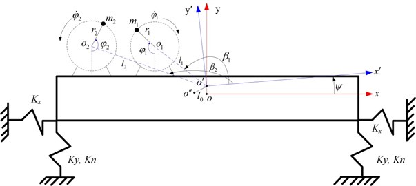
Where, and are the fixed coordinate system and moving coordinate system respectively. , , , , , are the displacements and velocities of the body in -, - and -directions. represents the mass center of the body, and are the rotating centers of the exciters 1 and 2 respectively. (1, 2) is the angle between the line from the rotational center of exciter to and -axis. is the distance between and . is the distance between the shaft center of exciter to . is the mass of the vibrating body. and are the mass of exciter and its eccentric radius. is the angle of exciter rotating around their own spindle.
Here we choose as the generalized coordinates, the kinetic energy , potential energy and dissipation energy are determined. Substituting them into the Lagrange equation:
And consider the following relations as ref. [19]:
Then, the five differential equations of the system can be obtained as follows:
where, and denote and respectively. is the total mass of the vibrating system, . is the electromagnetic torque of the exciter . is the moments of inertia of the system, , and are the calculated moments about the mass center and the exciter about its rotational center, is the moments of inertia of exciter , . and , are the equivalent resistance coefficient of motion and spring linear stiffness respectively. is the spring nonlinear stiffness in -direction. The indices of and can be obtained through data processing according to the curve of stiffness coefficient of the AB series spring of RostA used in the vibrating system.
2.2. Steady state solutions of the differential equations
Suppose the average angular velocity of the two exciters is when they operate synchronously in steady state. The average angular phase . If we assume their phase difference of two exciters is , the phase of exciter 1 and 2 can be described as:
Then, the average angular velocity and the angel accelerations of exciter 1 and 2 are , respectively. Thus, the angle accelerations and are so small that can be neglected in the first three equations in Eq. (3).
As for the second equation in Eq. (3), the elastic force of spring has hard characteristic as mentioned in Ref. [13]. That is, the spring has a weakly nonlinear stiffness. By using the method of equivalent linearization, we can establish an equivalent differential equation as described in Eq. (5) to replace the original equation:
where, . Now, the nonlinear elastic force can be expanded according to the method of Fourier series equation:
Generally speaking, the first harmonic force far outweighs the second harmonic force and the other high-order harmonic forces and the constant terms. Thus, they can be neglected and the approximate value can be obtained as follows:
where, the coefficients in Eq. (7) can be calculated according to the equation of Fourier series, finally, the equivalent stiffness is obtained as:
In actual engineering, the exciters belong to the same series and have similar physical construction, i.e., the exciter 1 and 2 have the same eccentric radius . The desired exciting force can be obtained by adjusting the active mass of the exciter, suppose . Introduce the following non-dimensional parameters: , , , , , , , then the first three equations in Eq. (3) can be simplified as Eq. (9):
Neglect the influence of damping ratio on the amplitude of the vibrating system, the meaningful solutions in -, -, -direction can be calculated through the principle of superposition of linear system, as shown in Eq. (10):
where:
3. Criterion of implementing synchronization and its stability criterion
3.1. Criterion of implementing synchronization
We can obtain the , and according to differentiating , and in Eq. (10), respectively. The rotational kinetic energy of exciters can be viewed as a constant when the exciters operate synchronously in steady state, denoted by (1, 2). Then, the kinetic energy and potential energy of the vibrating system can be simplified to:
And the Lagrange function can be replaced by . In a vibrating period , the Hamilton actions can be obtained, as shown in Eq. (12):
where:
According to Hamilton’s principle, in one vibrating period, the variation of the Hamilton actions plus the summation of integrals of the virtual work of the generalized force act in the vibrating system is zero. That is:
where, is the generalized force, is the generalized coordinates. If we choose as the generalized coordinates, substitute Eq. (12) into Eq. (13) yields:
where, , , , is the index of synchronization. As shown in Eq. (14), the two exciters must have a constant phase difference for the purpose of implementing the self-synchronous operation. At the same time, the absolute value must be less than or equal to 1. It means that the absolute value must be greater than or equal to the absolute value of the differences of to , or else, the phase difference in Eq. (14) does not have a solution, i.e., it is impossible to achieve a synchronization.
If one of the power supply of the exciters is turned off, suppose the exciter 2, in that case, . Substitute into Eq. (14), and replace by , if , it means that the non-powered exciter 2 is able to obtain certain energy by the vibration to compensate the work lost to overcome the frictional resistance moments.
3.2. Stability criterion of the synchronization operation
According to the theory of stability, we can deduce the stability criterion of the synchronization operation when the second-order derivative of the Hamilton actions with respect to is greater than zero, i.e.:
Differentiate the Hamilton actions in Eq. (12) with respect to yields the stability criterion:
From the Eq. (12), it can be found , thus, if and only if , the synchronization is stable. As shown in Eq. (16), the phase difference is related to the value of . The stable value of phase difference is in the following range:
Simultaneously, from Eq. (14), is equal to 0° or 180° when , that is, the stable value of will be bound to 180° when the vibrating system operates synchronously in steady state. It means that the relationship between the phase difference and is:
3.3. Two types motion law in a sub-resonant state and super-resonant state
Generally, an asynchronous vibrating machine in engineering has a close value of spring stiffness and damping, i.e., , and . In that case, we can further simplify in Eq. (12) as follows:
The following is a detail study and analysis of the phase difference and the motion path of the vibrating system operating in super-resonant state and sub-resonant state according to Eq. (12), Eq. (18) and Eq. (19).
3.3.1. Super-resonant
In that case, we have , i.e., . According to Eq. (19), will be smaller than zero when . It means that in Eq. (12). Also, as mentioned in Eq. (18), , we get the conclusion that the stable value of phase difference when the vibrating system operates in super-resonant. The phase difference will be stabilized in the vicinity of phase difference.
Alternatively, will be greater than zero when . We get when the vibrating system operates in super-resonant. In this condition, the moment of couple is obtained from the exciting forces of the two asymmetric exciters, which is intimately associated with the motion path at the mass center of the body. The vibrating direction of the center of mass of the body is from the center of mass to the center between the rotational center of Exciter 1 and Exciter 2. Meanwhile, because the middle point of the center line between the two exciters deflects from the center of mass of the body, a swing vibration appears which results in oval motions at the edges of the body. The motion path more generally at an arbitrary point of the body is listed in Eq. (20):
3.3.2. Sub-resonant
When the vibrating system operates in this state we have , i.e., . will be greater than zero in Eq. (18) when We have and , i.e., the phase difference will be stabilized in the vicinity of zero phase difference.
Alternatively, will be smaller than zero when . We get when the vibrating system operates in super-resonant. When the phase difference approaches to zero, the exciting forces of the two asymmetric exciters have the same direction, which will induce a large amplitude of the vibration in -direction and generate higher efficiency.
As a consequence of the above, we can find that the phase differences will be stabilized in the vicinity of Pi phase difference in a super-resonant state, otherwise, in the neighborhood of zero phase difference in a sub-resonant state when .
4. Experimental study
An experimental system was constructed in our Lab to validate the correctness of our theoretical analysis. Where, the synchronization machine powered by dual asymmetric exciters, approaches to . As shown in Fig. 2, the experimental system includes a mechanical composition, an electrical control cabinet and signal-collecting devices. Among this system, the mechanical composition of the vibrating system has two exciters (Fig. 2(a) and (b)), vibrating frame (Fig. 2(c)), four AB27 springs of RostA (Fig. 2(f)); the signal-collecting system includes two revolution speed transducers (Fig. 2(d)), three triaxial accelerometers (Fig. 2(e)), LMS SCADAS Mobile data acquisition system (Fig. 2(i)), and HIOKI PW 3335 power meter (Fig. 2(h)). The related mechanical parameters of the vibrating system are listed in Table 1.
To investigate whether the state of vibratory synchronization of the vibrating system can be achieved in a super-resonant state or sub-resonant state, we turn off the power supply of the Exciter 1 when 20 s, if possible. When the power supply frequency is mounted gradually, many experimental data are obtained in the sub-resonant and super-resonant states. The experimental results in steady state are listed in Table 2, especially, the detailed results in the super-resonant state and sub-resonant states are shown in Fig. 3 and Fig. 4, Fig. 5 and Fig. 6, respectively.
Table 1The parameters of the vibrating system
Item | Value |
Moment of inertia of vibrating body | 72.7 kg·m2 |
Total mass of vibrating system | 237.2 kg |
Stiffness coefficient in -direction | 105 N/m |
Linear stiffness coefficient in -direction | 10704 N/m |
Nonlinear stiffness coefficient in -direction (N/m) | 7.448 N/m |
Mass of each exciter (kg) multiplies its eccentric radius (m) | 0.170 kg·m |
Rated power | 0.37 kW |
Rated voltage | 380 v |
Rated speed of the motors | 1420 r/min |
Distance between the shaft center of exciter to and and (m) | 0.355 m, 0.687 m |
Angle between the line from the rotational center of exciter to and axis and | 163.24°, 171.44° |
Table 2The experimental results in steady state
Power supply frequency | Phase difference (degree) | Synchronization velocity of exciters (rpm) | Total power consumption of system (W) | |||
20 s | 20 s | 20 s | 20 s | 20 s | 20 s | |
210 rpm | –13.1° | - | 211.2 | – | 210.1 | – |
400 rpm | 196.5° | 178.7° | 402.5 | 393.1 | 112.8 | 81.9 |
600 rpm | 210.7° | 182.8° | 598.5 | 590.3 | 126.3 | 93.3 |
800 rpm | 220.6° | 202.5° | 801.6 | 791.8 | 144.9 | 113.1 |
1000 rpm | 220.7° | 212.3° | 1000.5 | 988.6 | 162.9 | 135.0 |
1200 rpm | 224.5° | 215.8° | 1198.3 | 1185.3 | 181.2 | 158.7 |
1400 rpm | 221.3° | 210.9° | 1391.5 | 1373.7 | 240.1 | 229.2 |
Fig. 2The experimental system
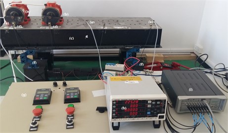
Table 2 and Fig. 3-6 show that this vibrating system can achieve a synchronization state when the system operates in a sub-resonant state and super-resonant state. Meanwhile, the vibratory synchronization state cannot be obtained in a sub-resonant state because the non-powered exciter isn’t able to capture adequate energy from the vibration of system to compensate the work lost to overcome the frictional resistance moments. In other states, the power supply of Exciter 1 is shut off when 20 s, both the phase difference and the rotational velocity of two exciters have a decrease, the system automatically can adjust the phase difference to achieve a new steady state of vibratory synchronization. At the same time, from Fig. 3(b) and Table 2 we note that the vibrating system obtains a more stable operating state and lower energy consumption state (more than 15 %) because the mutual interference between the two exciters is reduced along with cutting off the power supply of one exciter.
As shown in Fig. 3(b) and Fig. 5(b), the phase differences are stabilized in the vicinity of Pi phase difference (221.3°, 210.9°) in the super-resonant state, and in the neighborhood of zero phase difference (–13.1°) in the sub-resonant state.
Fig. 3a) The experimental results of dual asymmetric exciters operating in the super-resonant state, b) the rotational velocity of two exciters, c) the phase difference 2α between Exciter 1 and Exciter 2, d)-f) the total power supply of the vibrating system, g)-h) the acceleration on the left (middle, right) side of the vibrating frame. The motion path on the left (middle, right) side of the vibrating frame in steady state
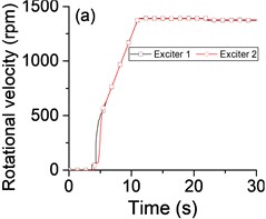
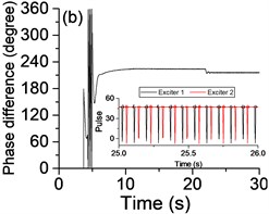
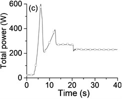
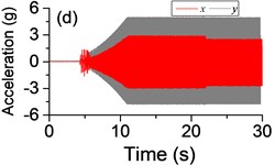
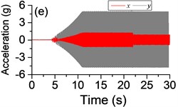
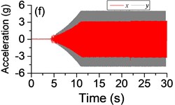
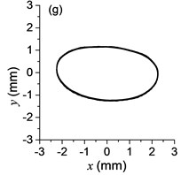
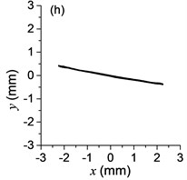
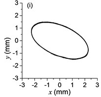
Fig. 4Phases of two exciters with frequency supply 1400 r/min in steady state after the power supply of Exciter 1 is shut off
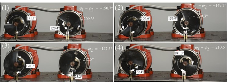
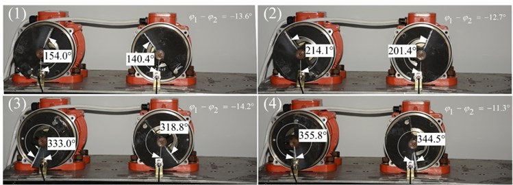
Fig. 4 is the phases of two exciters with frequency supply 1400 r/min in steady state after the power supply of Exciter 1 is shut off. Using the vertical as datum line, the phase difference is stabilized in the vicinity of Pi phase difference (209.3°-210.5°), this result is in accordance with the values listed in Table 2. Fig. 6 is the phases of two exciters with frequency supply 210 r/min in steady state. The phase differences are stabilized in the vicinity of zero phase difference (–11.3°-15.2°). Compared with the values listed in Table 2, there is a little deviation from the manual labeling the angles, but the correctness of theoretical study will be unaffected by it. Many other results are listed in Table 2 also essentially in agreement with the theoretical analysis results in section 3.
The difference of motion characteristic of the system in super-resonant and sub-resonant states denotes us two obviously steady operating states for a synchronous machine. For example, the vibrating angle of the mass center of our experimental system is 168.1° and the motion paths of the vibrating frame in steady state can be described by an oval as Fig. 3(g) and Fig. 3(i) when the system operates in a super-resonant state. The motion path at an arbitrary point e of the body can be described as Eq. (20). The amplitude of the vibration in -direction appropriates to 30 mm when the system operates in a sub-resonant state. To sum up, in engineering, the synchronization machines should be designed in a super-resonant state for the purpose of obtaining low energy consumption and more stable amplitude of responses and a higher exciting frequency, otherwise, the working points of the vibrating machines should be selected in a sub-resonant state in order to obtain the larger amplitude of responses.
Fig. 5a) The experimental results of dual asymmetric exciters operating in the sub-resonant state, b) the rotational velocity of two exciters, c) the phase difference 2α between exciter 1 and exciter 2, d)-f) the total power supply of the vibrating system, g)-h) the acceleration on the left (middle, right) side of the vibrating frame. The motion path on the left (middle, right) side of the vibrating frame in steady state
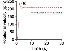
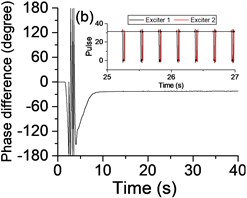
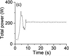
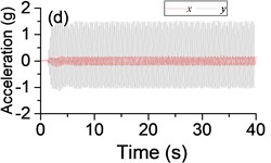
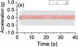
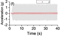
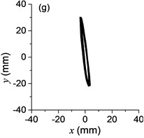
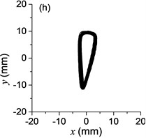
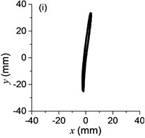
Fig. 6Phases of two exciters with frequency supply 210 r/min in steady state
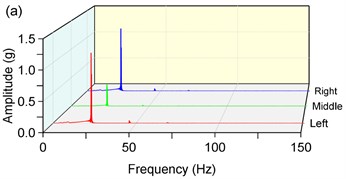
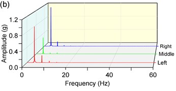
The Fast Fourier Transform (FFT) is applied to analyze the responses in -direction. As shown in Fig. 7, there is a finite number of harmonic-frequency components. It is worthwhile to note that there are non-fundamental frequency components which are integral multiples of the rotation frequency. At the same time, we note that the value of these components isn’t equal to the natural frequency. The phenomena can be attributed to the existence of the nonlinear factor in the vibrating system. As for the weakly nonlinear stiffness of the spring, we find that the weakly nonlinear factor plays an unimportant role. Relatively speaking, the nonlinear stiffness has a slightly greater influence on sub-resonant states than super-resonant states. But in general, there is a little error if we expand the nonlinear elastic forces by Fourier series expansion and ignore high-order harmonic forces and the constant terms. The equivalent stiffness obtained by the method of equivalent linearization can meet the required precision in engineering.
Fig. 7Amplitude-frequency characteristics in y-direction, a) 1400 rpm, b) 210 rpm
5. Conclusions
Through the theoretical investigation and experimental study given in the former sections, some useful conclusions should be stressed.
For a nonlinear vibrating synchronization system mentioned in this paper, the weakly nonlinear elastic forces can be expanded by Fourier series expansion and ignored high-order harmonic forces and the constant terms. The results of this method can meet the required precision in engineering.
When approaches to , the phase differences of two asymmetric exciters rotating in opposite directions are stabilized in the vicinity of Pi phase difference in the super-resonant state, otherwise, in the neighborhood of zero phase difference in the sub-resonant state. The vibratory synchronization state cannot be obtained in a sub-resonant state; however, the vibratory synchronization state can be obtained easily in a super-resonant state. In engineering, the working points of this kind of vibrating machines should be designed in a sub-resonant state when we need larger amplitude of responses. This kind of vibratory synchronization machine can be designed in a super-resonant state for the purpose of obtaining low energy consumption and more stable amplitude of responses.
References
-
Blekhman I. I. Self-synchronization of vibrators in some types of vibration machines. Inzhenerny Sbornik, Vol. 16, 1953, p. 49-72.
-
Sh K. K. Synchronization of the mechanical vibrators related to the linear oscillatory system. Izvestiya Akademii Nauk SSSR, MTT, Vol. 4, 1967, p. 14-24.
-
Blekhman I. I., Fradkov A. L., Nijmeijer H., et al. Control of chaos and synchronization on self-synchronization and controlled synchronization. Systems and Control Letters, Vol. 31, Issue 5, 1997, p. 299-305.
-
Inoue J., Araki Y. Self-synchronization of mechanical system. Proceedings of Japanese Mechanical Engineering Society, Vol. 42, 1981, p. 103-110.
-
Zhao C., Zhao Q., Gong Z., et al. Synchronization of two self-synchronous vibrating machines on an isolation frame. Shock and Vibration, Vol. 18, Issues 1-2, 2011, p. 73-90.
-
Zhao C., Zhu H., Zhang Y., et al. Synchronization of two coupled exciters in a vibrating system of spatial motion. Acta Mechanica Sinica, Vol. 26, Issue 3, 2010, p. 477-493.
-
Zhao C., Zhu H., Wang R., et al. Synchronization of two non-identical coupled exciters in a non-resonant vibrating system of linear motion. Part I: Theoretical analysis. Shock and Vibration, Vol. 16, Issue 5, 2009, p. 505-515.
-
Zhao C., Wen B., Zhang X. Synchronization of the four identical unbalanced rotors in a vibrating system of plane motion. Science China-Technological Sciences, Vol. 53, Issue 2, 2010, p. 405-422.
-
Zhang X.-L., Zhao C.-Y., Wen B.-C. Theoretical and experimental study on synchronization of the two homodromy exciters in a non-resonant vibrating system. Shock and Vibration, Vol. 20, Issue 2, 2013, p. 327-340.
-
Zhang X.-L., Wen B.-C., Zhao C.-Y. Synchronization of three homodromy coupled exciters in a non-resonant vibrating system of plane motion. Acta Mechanica Sinica, Vol. 28, Issue 5, 2012, p. 1424-1435.
-
Zhang X., Wen B., Zhao C. Experimental investigation on synchronization of three co-rotating non-identical coupled exciters driven by three motors. Journal of Sound and Vibration, Vol. 333, Issue 13, 2014, p. 2898-2908.
-
Zhang X., Kong X., Wen B., et al. Numerical and experimental study on synchronization of two exciters in a nonlinear vibrating system with multiple resonant types. Nonlinear Dynamics, Vol. 82, Issues 1-2, 2015, p. 987-999.
-
Li Y., Li H., Wei X., et al. Self-synchronization theory of a nonlinear vibration system driven by two exciters. Part 1: Theoretical analysis. Journal of Vibroengineering, Vol. 16, Issue 2, 2014, p. 725-734.
-
Li H., Liu D., Li Y., et al. The self-synchronous theory of a dual-motor driven vibration mechanism without shimmy. Archive of Applied Mechanics, Vol. 85, Issue 5, 2015, p. 657-673.
-
Li X., Liu J. Analysis of the frequency catching sharp resonance synchronization theory of nonlinear vibration machine. Journal of Computational and Theoretical Nanoscience, Vol. 4, Issue 4, 2011, p. 1842-1846.
-
Warminski J., Balthazar J. M., Brasil R. M. L. R. F. Vibrations of a non-ideal parametrically and self-excited model. Journal of Sound and Vibration, Vol. 245, Issue 245, 2001, p. 363-374.
-
Blekhman I. I. A. I. Synchronization in Science and Technology. ASME Press, 1988.
-
Zhang X. L., Liu Y. S., Wen B. C., et al. Synchronization of dual unbalanced rotors in a vibrating system with double resonant types. Journal of Vibration Engineering and Technologies, Vol. 3, Issue 6, 2015, p. 769-778.
-
Wen B. C., Fan J., Zhao C. Y., et al. Vibratory and Controlled Synchronization Engineering. Science Press in China, Beijing, 2009.
Cited by
About this article
This research is supported by the project of National Science Foundation of China (51305070) and the science and technology research project of Liaoning Provincial Department of Education (L2014092). We are grateful to my students, Chuixi Zeng and Jinglei Nie, who performed the experiments.
