Abstract
Taking the multi point winding hoisting system with depth of 1000 m, drum radius of 0.4 m, drum radius difference of 0.1 mm as the research background, a model of multi point winding hoisting system under non synchronous movement of wire ropes is established, and the mathematical model is deduced by Lagrange equation. Then the dynamic characteristic of super deep multi point winding hoisting system under non synchronous movements of wire ropes is analyzed. The results show that: the rotational displacement of mass block is 5°, the rotational velocity is 0.07 °/s in the stage of constant speed. The rope length difference reaches 0.07 m, the tension of each wire rope changes 333 N, accounted for about 7 % of the average tension. And with the length difference increasing 35 mm, the force differences increasing 320 N, which indicates that the length difference has great impact on the tension difference of wire ropes. Finally, the mathematical model is verified through experiment.
Highlights
- The manuscript proposed a mathematical model of multi point winding hoisting system under non synchronous movements of wire ropes in deep well,and then solved it by using the numerical method.
- The wire rope is equivalent to an elastic body with certain stiffness and damping.
- The nonlinear terms in the equations are ignored to facilitate the solution of the equations.
- The experiment of multi point winding hoisting system is designed.
- The numerical results of the mathematical model of the experimental bench is used to make a comparison with the experimental results to verify the validity of the mathematical model.
1. Introduction
In the process of coal mining, the main equipments are single point winding hoisting system with hoisting height below 1000 m. But the hoisting depth and hoisting loads of single point winding hoisting is limited, so it is necessary to design a new kind hoisting system to meet the hoisting requirements of bigger hoisting depth and larger hoisting loads. The multi point winding hoisting system have advantages of bigger hoisting depth, larger hoisting loads and better control performance compared with single point winding hoisting system, so it is expected to be a solution to the problems existing in the single point winding hoisting system. However, due to the radius difference of the driving drums, head sheaves and the difference of physical properties of wire ropes, the movements of wire ropes are not synchronized in the process of operating multi point winding hoisting system. And thus, the tension of wire ropes has certain difference, that is the tension of one wire rope is larger, while the other is smaller. For the wire rope of larger tension, the phenomenon of rope fatigue and even rope broken will occur when the tension exceeds a certain value due to the influence of dynamic loads, which make the hoisting system cannot run normally and even has safety problems. Therefore, it is necessary to study the characteristics in the hoisting process of the multi point winding hoisting system and the stress of the wire ropes under non synchronous movements. Zhou tong [1] equated the wire rope isolator to an elastic body with certain stiffness and damping coefficient and established the mechanical model of the wire rope isolator. Wu Renyuan [2] also equated the wire rope to an elastic body with certain stiffness and damping coefficient and established the mathematical model of the elevator lifting system. Yang Li [3] studied the vibration characteristics of wire rope with variable length under excitation at both ends using mathematical model. Wang Shaojin [5] obtained the tension difference between the wire ropes of the multi rope hoisting system under the condition of different radius of liner through a set of new methods. Xu Yaping [6] acquired the tension of two ropes through simulating method. Rega [15] discussed the nonlinear vibrations of elastic suspended cables by system modeling and methods of analyzing. In this article, taking the multi point winding hoisting system in super deep well as research object, a model of multi point winding hoisting system under non synchronous movements of ropes is established, and through deducing the mathematical model by Lagrange equation, the dynamic characteristics of multi point winding hoisting system in super deep well is analyzed, which provided a certain reference for the design of multi point winding hoisting system.
2. Establishment of mechanical model
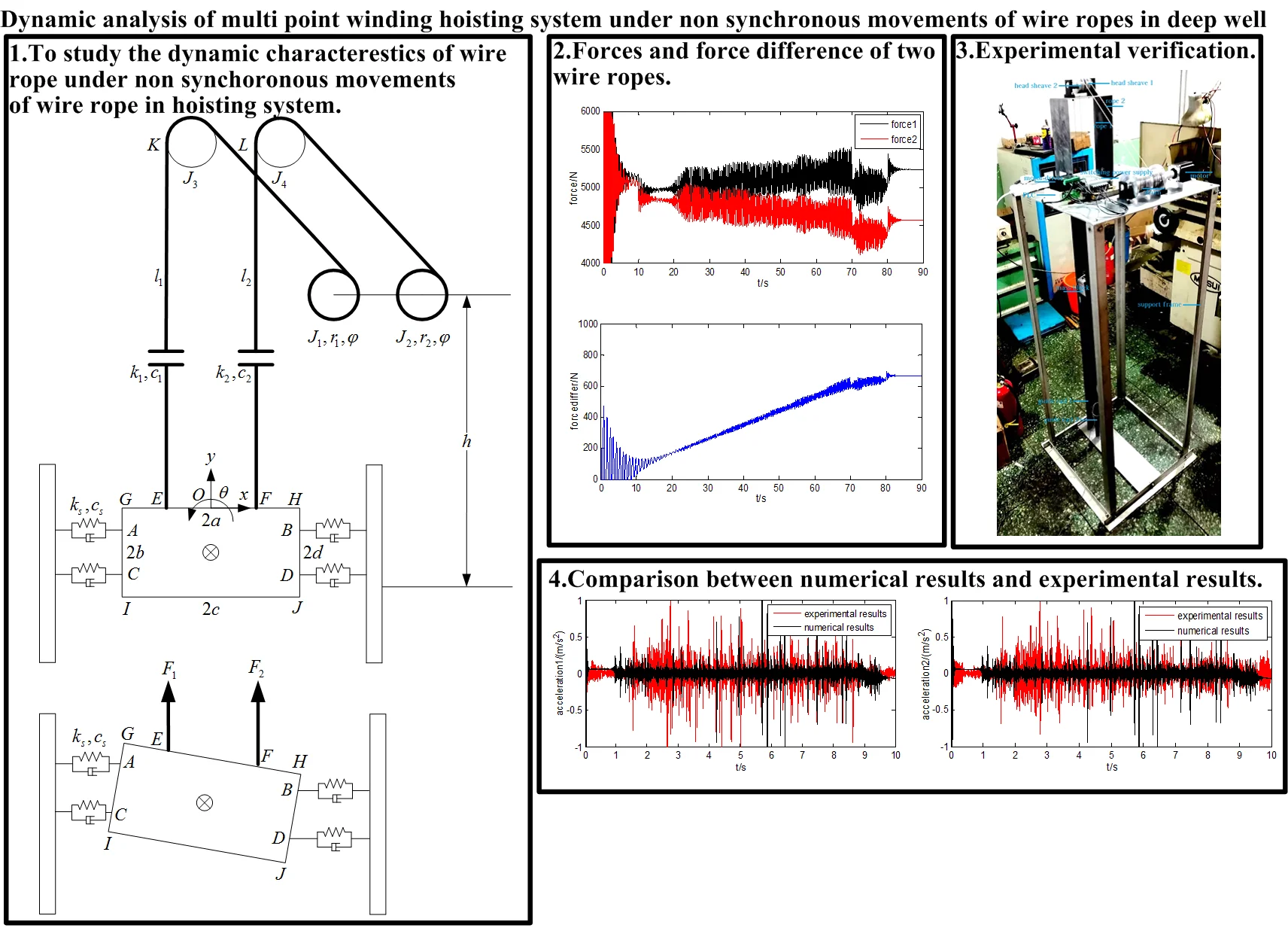
In this paper, a multi point winding hoisting system is studied. The multi point winding hoisting system mainly includes guiding rail, guiding rollers, mass block, wire ropes, head sheaves and driving drums.
Before establishing the mathematical model of winding hoisting system, there are two assumptions: 1. The transverse vibration of the wire ropes is ignored in order to analyze the longitudinal vibration. 2. The system is linearized because the nonlinear terms can cause little effect to the results of longitudinal vibration.
In order to establish the mechanical model, the model of wire rope and guiding rollers are simplified. The specific method is: the wire rope and guiding rollers are equivalent to an elastic body with certain stiffness and damping. And a generalized coordinate system is established by taking the position of the midpoint on the top of the mass block at initial position as the origin of the coordinate system. Then selecting the coordinate , coordinate and coordinate of mass block as the generalized coordinates. Finally setting the mass of mass block as , the moment of inertia as , the stiffness coefficient of guiding rollers as , the damping coefficient as , the initial length of wire rope 1 as ,the stiffness coefficient of wire rope 1 as , the damping coefficient of wire rope 1 as , the initial length of wire rope 2 as ,the stiffness coefficient of wire rope 2 as ,the damping coefficient of wire rope 2 as , the unit length mass of wire rope as , the moment of inertia of drums as and , the radius of wheel and drum as and , the angular displacement of drums as , the distance from the center of driving drums to the center of mass block as , and the moment of inertia of wheels as and . The models are shown as Fig. 1 and Fig. 2.
Fig. 1Mechanical model of winding hoisting system
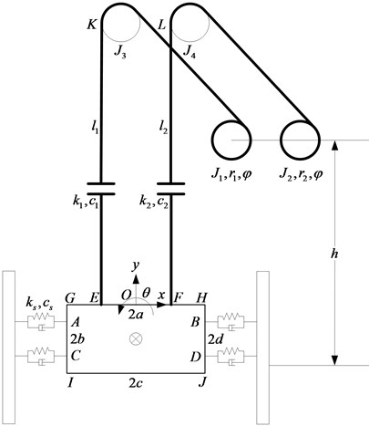
Fig. 2Model of wire ropes of non synchronous movements
The parameters of mass block are as below:
The displacements are expressed as following:
The angular displacement of point and are and .
Then the mechanical model of winding hoisting system under non accordance of wire ropes is established.
3. Establishment of mathematical model
In this paper, the differential equation of motion of the system is established basing on Lagrange equation with dissipation function, the expression is as following:
Within Eq. (3), represents the Lagrange function, and , represents the dynamic energy of the system, represents the potential energy of the system, represents the dissipative function, represents the generalized force corresponding to the generalized coordinate, and represent the generalized displacement and velocity.
First calculating the dynamic energy of the system , and can be expressed as following:
Within Eq. (4), represents the dynamic energy of mass block, and represent the dynamic energy of the wire ropes, and represent the dynamic energy of head sheaves, and represent the dynamic energy of the wire ropes winding on the drums, and represent the dynamic energy of drums.
The dynamic energy of mass block as can be expressed as following:
To calculate the dynamic energy and of the wire ropes, the displacements at each point of wire ropes have to be provided.
Setting the displacement of one point at wire rope 1 as , the displacement of one point at wire rope 2 as , and the distance from the connected point between wire ropes and mass block to one point at wire ropes as . Suppose the displacement distribution on the wire rope is linear, then the exression of and can be acquired:
Then the dynamic energy of the wire ropes and can be deduced:
The dynamic energy of head sheaves and can be deduced:
The dynamic energy of the wire ropes winding on the drums and are calculated as following:
By substituting and into Eq. (11), Eq.(11) can be transferred to the following expression:
The dynamic energy of drums and can be expressed as below:
Finally, from Eq. (5) to Eq. (13), the dynamic energy of the system can be summed up and calculated as following:
And then calculating the potential energy of the system . The potential energy of the system can be calculated as following:
Within Eq. (15), is the potential energy of head sheaves and drums which are constant value, is the stiffness coefficient between guiding rollers and guiding rails.
Then the Lagrange function can be calculated as following:
And the dissipative function can also be deduced as following expression:
Within Eq. (17), is the damping coefficient between guiding rollers and guiding rails.
Then substituting the Lagrange function and the dissipative function into Eq. (3), the Lagrange equation can be transferred to three equations. Finally, through ignoring the nonlinear terms in the three equations, the following equations can be acquired:
To calculate the ordinary differential equations, the method of order reduction is adopted. The specific method is as following:
Then Eq. (18) to Eq. (20) can be transferred to Eq. (22) to Eq. (24) as following:
Meanwhile there are relationships between the variables. The relationships are shown in the following equation:
Then a simple ordinary differential equation of first order can be obtained:
Within Eq. (26), the matrix , , and are expressed as following:
Finally, the mathematical model of multi point winding hoisting system under non synchronous movements has been established.
4. Solution of mathematical model
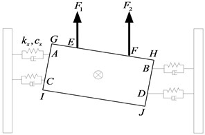
For the hoisting system, the operating process of winding hoisting system is divided into four stages, including stages of speed in acceleration, speed of constant, speed in deceleration and stop. Setting the angular acceleration as . The relationships between the angular displacement and time during the four stages of hoisting process are shown as the following expressions:
The change of drum acceleration is shown in the Fig. 3.
Fig. 3Acceleration of drums
The initial value of the variables are as below:
The parameters of the multi point winding hoisting system are shown in Table 1.
The stiffness of wire ropes can be calculated as and ,within that is the actual length of wire ropes including vertical section and inclined section. The damping coefficient and of wire ropes are ignored because they can cause little effect to the results of longitudinal vibration.
Then the Eq. (26) can be solved numerically. And the results can be obtained as following.
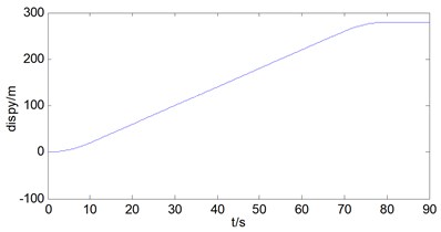
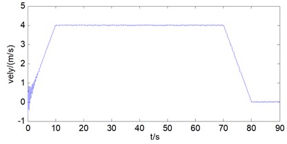
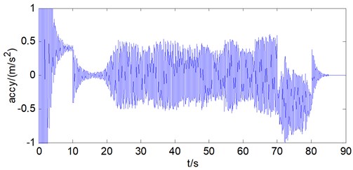
The longitudinal vibration condition of the mass block is analyzed. As can be seen from Fig. 4.
Through the analysis of the longitudinal displacement of the mass block, it can be found that the longitudinal displacement of the mass block is 280 m, the longitudinal velocity reaches 4 m/s in the constant speed stage, and there is an amplitude fluctuation of 0.05 m/s, at last the longitudinal acceleration is between –0.5 m/s2 and 0.5 m/s2 in the constant speed stage. Meanwhile, there is amplitude fluctuation of the acceleration, the reason is that there is elasticity for the wire rope, so there is longitudinal vibration of the wire rope during the hoisting process.
Table 1Operating parameters of winding hoisting system
Hoisting mass (kg) | 1000 |
Unit length mass of wire rope (kg) | 0.41 |
Rotation radius of drum 1 (m) | 0.4001 |
Rotation radius of drum 2 (m) | 0.4 |
Moment of inertial of drum , , , (kg.m2) | 1000 |
The horizontal distance between the wire rope and the center of the mass block (m) | 0.4 |
The vertical distance between the guiding rollers and the center of the mass block (m) | 0.2 |
Half width of mass block (m) | 0.6 |
Elastic module of wire rope (pa) | 1.2e+11 |
Cross section area of wire rope (m2) | 8e-4 |
Initial length of wire rope (m) | 1000 |
Damping coefficient of wire rope , (N.s/m) | 1000 |
Angular acceleration of the drum in accelerated and decelerated phase of operation (rad/s2) | 1 |
Time (s) | 10 |
Time (s) | 110 |
Time (s) | 120 |
Time (s) | 150 |
Stiffness coefficient of guiding rollers (N/m) | 1000 |
Damping coefficient of guiding rollers (n.s/m) | 1000 |
Fig. 4a) Longitudinal displacement of mass block, b) longitudinal velocity of mass block, c) longitudinal acceleration of mass block
a)
b)
c)
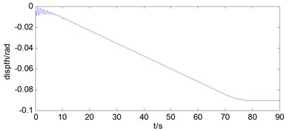
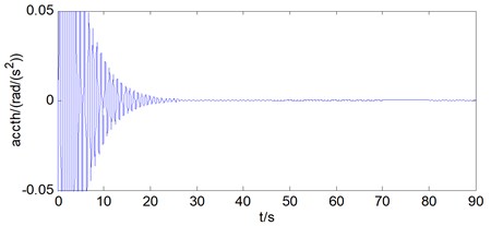
Then the rotational vibration condition of the mass block is analyzed. As can be seen from Fig. 5.
Through the analysis of the rotational displacement of the mass block, it can be found that the rotational displacement of mass block is 5° in the hoisting process with wire ropes under non synchronous movements, the rotational velocity is 0.07 °/s in the stage of constant speed, and the rotational acceleration basically changes as the same form as the rotational velocity, and tends to be 0 in the stage of constant speed.
Fig. 5a) Rotational displacement of mass block, b) rotational velocity of mass block, c) rotational acceleration of mass block
a)
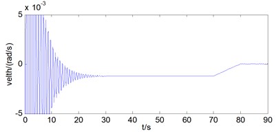
b)
c)
Also the length difference of ropes is analyzed in the hoisting process with wire ropes under non synchronous movements. The result are shown in Fig. 6.
Fig. 6Length difference of ropes
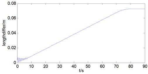
The results show that the final rope length difference is 0.07 m in the hoisting process with wire ropes under non synchronous movements.
Finally analyzing the forces of wire ropes in the hoisting process with wire ropes under non synchronous movements.
The forces of wire ropes satisfy the following equations:
Within Eq. (34), is half distance of which can be seen from Fig. 1.
Then the forces of two wire ropes can be acquired by the following equations:
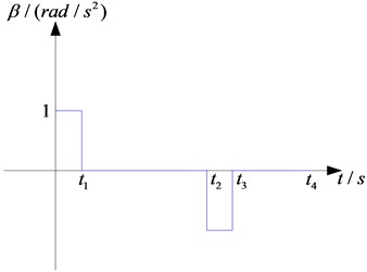
So the tension of wire ropes of hoisting system can be got. As can be seen from Fig. 7.
Fig. 7a) Load force of point E and point F, b) force differences of wire ropes
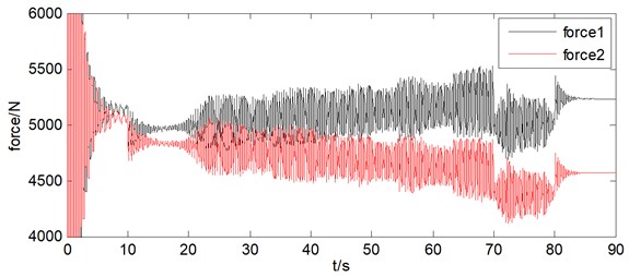
a)
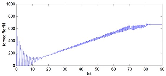
b)
Through the forces analysis of wire ropes under non synchronous movements, the tension of wire rope 1 varies from 4900 N to 5233 N, the tension of wire rope 2 varies from 4900 N to 4567 N, both tension of two ropes change 333 N, which accounted for about 7 % of the average tension. And in the hoisting process the length difference of two wire ropes is 0.07 m as well as tension difference is 666 N under non synchronous movements of wire ropes, which indicates that the length difference of wire ropes have great impact on the tension difference of wire ropes.
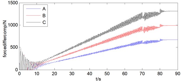
5. Comparison of length difference and force difference under radius difference
By comparing the length difference and force difference under radius difference, the influence brought by the radius difference can be obtained. The results are shown as Fig. 8 and Fig. 9. And in the figures, letter A represents radius difference of 0.1 mm, B represents radius difference of 0.15 mm, and C represents radius difference of 0.2 mm.
Through the results above, it can be found that with the radius difference increasing, the length difference and force difference are also increasing. And with length difference increasing 35 mm, the force differences increasing 320 N, which shows that the length difference can cause large effect on the tension differences between wire ropes.
6. Experimental verification for mathematical model
In order to further verify the validity of the mathematical model, the experiment was carried out to compare with it. First, a testing bench of multi point winding hoisting system under non synchronous movements of wire ropes was built, then the test of the hoisting system was carried out, and the data were collected to obtain the longitudinal hoisting acceleration of wire rope 1 and wire rope 2. Finally, the parameters of the test bench are put into the mathematical model, and the output results are obtained through numerical calculation, including the longitudinal hoisting displacement, longitudinal hoisting velocity and longitudinal hoisting acceleration of the wire ropes. Longitudinal hoisting acceleration includes acceleration of wire rope 1 and wire rope 2. The validity of the mathematical model can be verified by comparing the results of the hoisting acceleration of the test bench with the results of the mathematical model, so it can be used to provide reference and basis for the analysis of the characteristics of the hoisting system by using the mathematical model.
Fig. 8Length difference of different radius difference
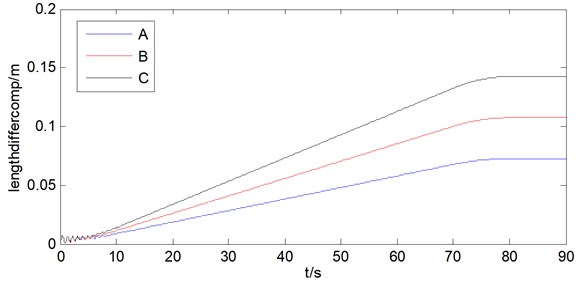
Fig. 9Force difference under of radius difference
The established test bench of multi point winding hoisting system under non synchronous movements of wire ropes is shown in Fig. 10. The test bench is mainly composed of motor, drum, PLC, motor driver, switching power supply, wire ropes, head sheaves, guide rails, mass block and support frame. The guide rails are shown in Fig. 11. Since it is necessary to measure the acceleration of two wire ropes, two acceleration sensors are adopted, and the installation position of sensors is shown in Fig. 12. The test equipment is mainly composed of data acquisition instrument, dynamic testing and analyzing software and PC, as are shown in Fig. 13. The observation results in experiment are shown in Fig. 14 and Fig. 15. The acceleration of wire rope 1 and wire rope 2 are shown in Fig. 16 and Fig. 17.
By observing Fig. 15, it can be found that when the hoisting process finished, the mass block leaned to the left side because the length of vertical section of wire rope 1 is less than the length of wire rope 2. This is because the diameter of the winding part for wire rope 1 is larger than that of wire rope 2. At the same time, it can be found that the hoisting acceleration of the two wire ropes is generally between –0.5 m/s2 and 0.5 m/s2.
Fig. 10Test bench of multi point winding hoisting system under non synchronous movements of wire ropes
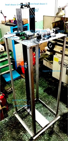
Fig. 11Guide rails
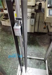
Fig. 12Installation position of sensors
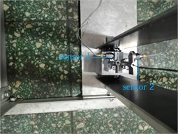
Fig. 13Testing equipment

Fig. 14Experimental observation result 1
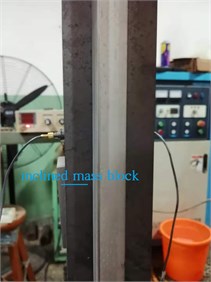
Fig. 15Experimental observation result 2
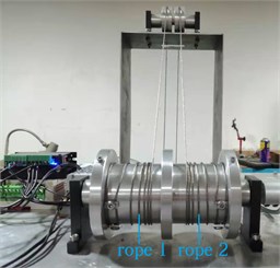
Fig. 16Longitudinal hoisting acceleration of wire rope 1 of testing bench
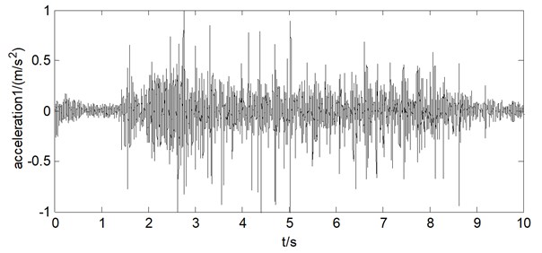
Fig. 17Longitudinal hoisting acceleration of wire rope 2 of testing bench
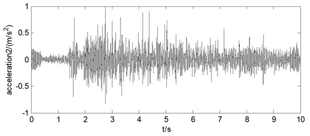
Table 2Operating parameters of winding hoisting system for comparison
Hoisting mass (kg) | 1 |
Unit length mass of wire rope (kg) | 0.014 |
Rotation radius of drum 1 (m) | 0.03 |
Rotation radius of drum 2 (m) | 0.0301 |
Moment of inertial of drum , , , (kg.m2) | 3.88e-4 |
The horizontal distance between the wire rope and the center of the mass block (m) | 0.015 |
The vertical distance between the guiding rollers and the center of the mass block (m) | 0.0085 |
Half width of mass block (m) | 0.04 |
Elastic module of wire rope (pa) | 1.1e11 |
Cross section area of wire rope (m2) | 1.77e-6 |
Initial length of wire rope (m) | 2.5 |
Damping coefficient of wire rope , (N.s/m) | 50 |
Angular acceleration of the drum in accelerated and decelerated phase of operation (rad/s2) | 2 |
Time (s) | 1 |
Time (s) | 9 |
Time (s) | 10 |
Time (s) | 10 |
Stiffness coefficient of guiding rollers (N/m) | 10 |
Damping coefficient of guiding rollers (n.s/m) |
Through numerical simulation, the acceleration results of the longitudinal hositing accelerations of the two wire ropes are acquired through numerical calculation. The results are shown in Fig. 18 and Fig. 19.
Fig. 18Longitudinal hoisting acceleration of wire rope 1 by numerical calculation
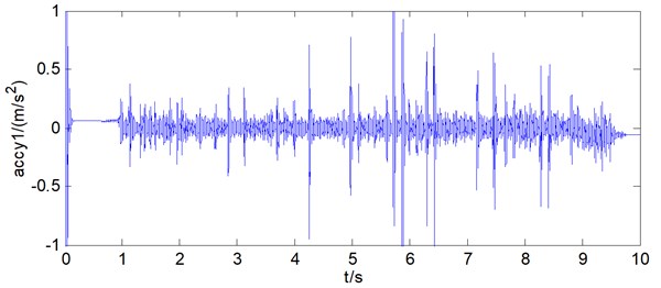
By observing Fig. 18 and Fig. 19, it can be found that the longitudinal hoisting acceleration of the two wire ropes was basically between –0.5 m/s2 and 0.5 m/s2, and generally changes within the same range as the results obtained from the test bench. At the same time, by further comparing the data obtained from the test bench and the mathematical model, it can be found that the two data are basically consistent. As can be seen from Fig. 20 and Fig. 21.
Fig. 19Longitudinal hoisting acceleration of wire rope 2 by numerical calculation
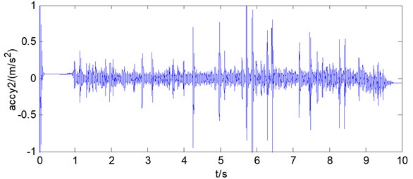
Fig. 20Comparison of acceleration for wire rope 1
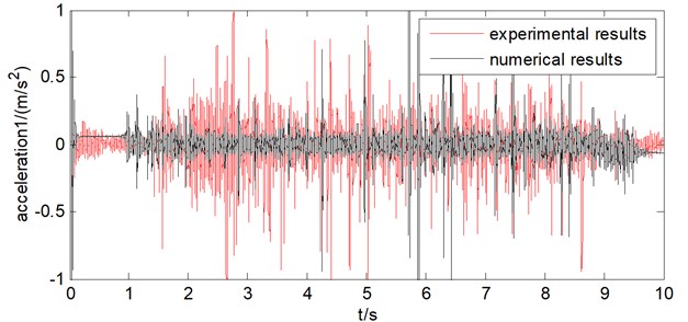
Fig. 21Comparison of acceleration for wire rope 2
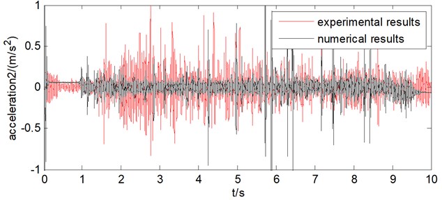
By comparing the results of acceleration of the two wire ropes obtained from testing data of the test bench and numerical calculation of the mathematical model under the condition of non synchronous movements of wire ropes, it can be seen that the two results are basically consistent and generally vary from –0.5 m/s2 to 0.5 m/s2. Therefore, the rationality and validity of the established mathematical model are proved, which can provide a basis for the analysis of dynamic characteristics of the 1000 m hoisting system, and thus provide a certain reference value for the design and manufacture of the hoisting system for super deep wells.
7. Conclusions
Taking the multi point winding hoisting system with depth of 1000 m, drum radius of 0.4 m, drum radius difference of 0.1 mm as the research background, a model of multi point winding hoisting system under non synchronous movements of wire ropes is established, and the dynamic characteristics of the hoisting system are analyzed. The conclusions are as following.
1) During the hoisting process with wire ropes under non synchronous movements of wire ropes, the longitudinal displacement of the mass block is 280 m, the longitudinal velocity reaches 4m/s in the constant speed stage, and there is an amplitude fluctuation of 0.05 m/s, at last the longitudinal acceleration is between –0.5 m/s2 and 0.5 m/s2 in the stage of constant speed.
2) During the hoisting process with wire ropes of non synchronous movements, the rotational displacement of mass block is 5°, the rotational velocity is 0.07°/s in the stage of constant speed, and the rotational acceleration changes the same form as the rotational velocity, and tends to 0 in the stage of constant speed.
3) During the hoisting process with wire ropes of non synchronous movements, the rope length difference reaches 0.07 m, the tension of each wire rope changes 333 N, accounted for about 7 % of the average tension.
4) With the length difference increasing 35 mm, the force differences increasing 320 N, which indicates that the length difference has great impact on the tension difference of wire ropes.
5) The results of acceleration of the two wire ropes obtained from testing data of the test bench and numerical calculation of the mathematical model under the condition of non synchronous movements of wire ropes are basically consistent, therefore verifying the rationality and validity of the established mathematical model, which provides a certain reference value for the design and manufacture of the hoisting system for super deep wells.
6) For further study the effect of tension imbalance of wire ropes, direct tension testing results could be a more efficient way to make comparison with the results of the mathematical model.
References
-
Zhou Tong, Liu Qinglin Simplified model analysis of wire-rope vibration isolator. Journal of Vibration and Shock, Vol. 26, Issue 9, 2007, p. 55-59.
-
Wu Ren-Yuan, Cao Guo Hua, Yue Ling Dynamic modeling and simulation of tractional elevator. Manufacturing Automation, Vol. 7, 2015, p. 87-90.
-
Yang Li, Chen Enwei, Liu Zhengshi Analysis of transverse vibration for an axially travelling string with variable length under boundary load. Journal of Hefei University of Technology: Natural Science, Vol. 8, 2018, p. 1014-1018.
-
Zhang C. Y., Zhu C. M., Fu W. J. Nonlinear lateral vibration of the hoist rope in vertical hoist system. Shanghai Jiaotong Daxue Xuebao, Vol. 38, Issue 2, 2004, p. 286-290.
-
Wang S. J., Yang Z. J., Du F. Study on the method of multi-rope hoist rope tension imbalance fault monitoring and diagnosis. Advanced Materials Research, Vol. 139, Issue 141, 2010, p. 2591-2594.
-
Xu Yaping, Yang Fang, Li Jishun, Zou Shengyong Simulation and test verification on tension of wire rope of double-rope winding hoist. Mining and Processing Equipment, Vol. 48, Issue 1, 2020, p. 16-20.
-
Kun, Zou, Dujian, Wei, Minghai Nonlinear analysis of cable vibration of a multispan cable-stayed bridge under transverse excitation. Mathematical Problems in Engineering, Vol. 2014, 2014, p. 832432.
-
Yang W. L., Wang Z. B., Yan B. L. Modeling and dynamic simulation of cable. Applied Mechanics and Materials, Vol. 256, Issue 259, 2012, p. 2863-2866.
-
Bin L., Yinghui L., Xuegang Y. Dynamic modeling and simulation of flexible cable with large sag. Applied Mathematics and Mechanics, Vol. 21, Issue 6, 2012, p. 707-714.
-
Bin Z. I. Dynamic modeling and numerical simulation of cable-driven parallel manipulator. Journal of Mechanical Engineering, Vol. 43, Issue 11, 2007, p. 82-88.
-
Jiang J., Li G. Q., Lu Y. Vibration control of cables with damped flexible end restraint: Theoretical model and experimental verification. Journal of Sound and Vibration, Vol. 332, Issue 15, 2013, p. 3626-3645.
-
Impollonia N., Ricciardi G., Saitta F. Dynamic behavior of stay cables with rotational dampers. Journal of Engineering Mechanics, Vol. 136, Issue 6, 2010, p. 697-709.
-
Zi Fan F. Dynamics modeling and simulating of steel cable structure. Hoisting and Conveying Machinery, 2009.
-
Cai Y., Chen S. S. Dynamics of elastic cable under parametric and external resonances. Journal of Engineering Mechanics, Vol. 120, Issue 8, 1994, p. 1786-1802.
-
Rega, Giuseppe Nonlinear vibrations of suspended cables - part I: modeling and analysis. Applied Mechanics Reviews, Vol. 57, Issue 6, 2004, p. 443.
-
Rega G. Nonlinear vibrations of suspended cables - part II: deterministic phenomena. Applied Mechanics Reviews, Vol. 57, Issue 6, 2004, p. 479-514.
Cited by
About this article

