Abstract
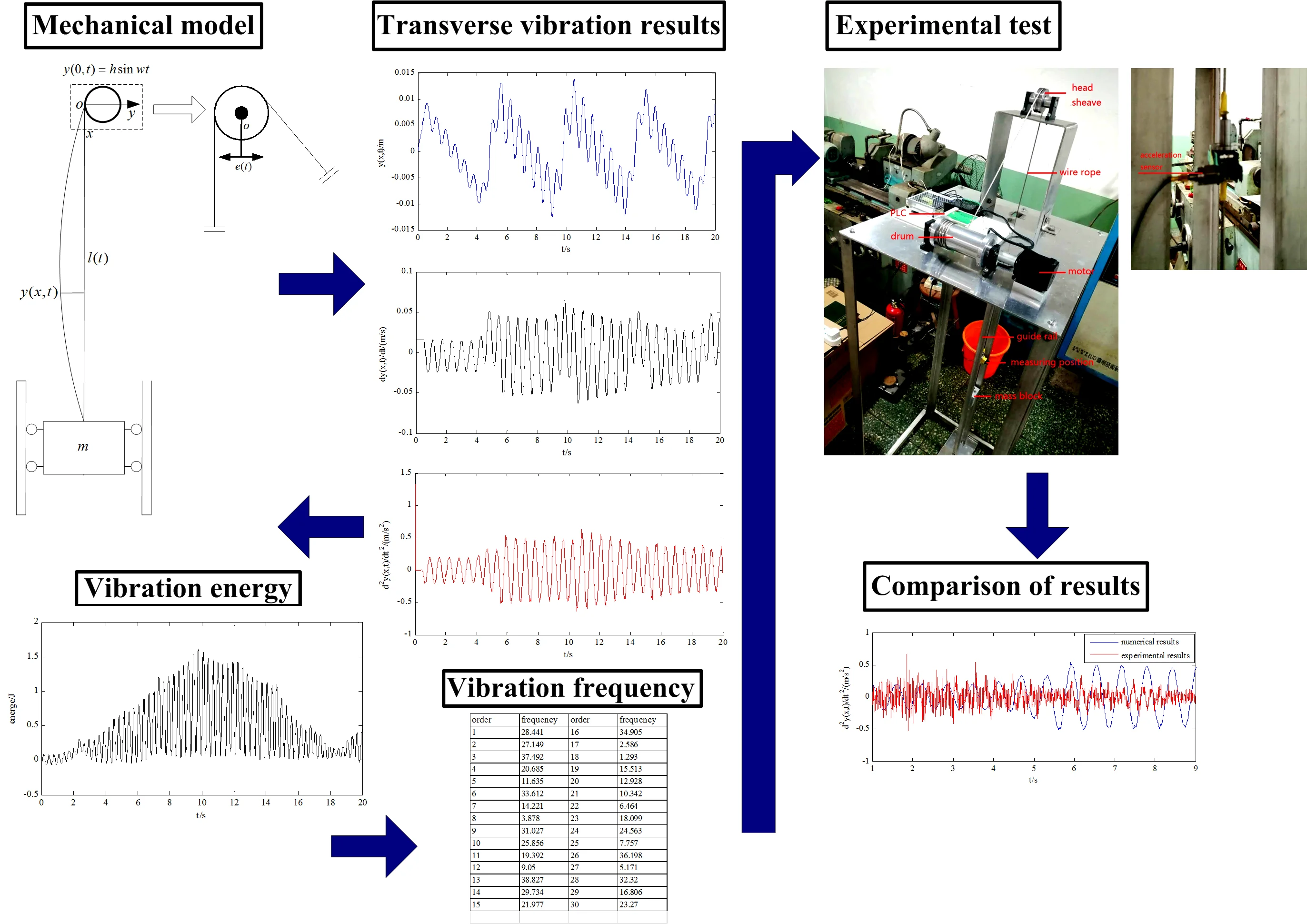
In this paper, the transverse vibration displacement, velocity and acceleration of the wire rope of deep mining hoisting system is acquired by establishing a mathematical model and solving it by Galerkin discrete method. The results show that: for the deep mining hoisting system with hoisting depth of 1000m and hoisting load of 25 t, when there is an excitation with amplitude of 0.002 m and frequency of 10 Hz at one end, the transverse vibration displacement of the wire rope at 200 m is between -0.015 m and 0.015 m, the transverse vibration velocity is between –0.05 m/s and 0.05 m/s, and the transverse vibration acceleration is between –0.5 m/s2 to 0.5 m/s2. Meanwhile, it can be found that different loads, accelerations and mass of wire rope per unit length have little influence on the transverse vibration displacement of the wire rope, but different external excitation frequency have an impact on the transverse vibration displacement of the wire rope. Then the vibration energy and natural frequencies are analyzed. And the maximum vibration energy and 30 natural frequencies are obtained. Finally, the mathematical model is verified through the experiment and the validity of the mathematical model is proved.
Highlights
- The transverse vibration model under excitation at one end of wire rope in hoisting system is established and solved.
- The transverse vibration displacements,velocity and acceleration are calculated.
- The influence of loads,accelerations,mass of wire rope per unit length and external excitation frequency are calculated.
- The energe of the wire rope is calculated.
- The vibration frequencies of the wire rope are calculated.
- The experimental test of the hoisting system is carried to verify the rationality of the mathematical model.
1. Introduction
In the working process of mine hoisting system, the wire rope of hoisting system will produce certain longitudinal and transverse vibration in the hoisting process. For the longitudinal vibration, the wire rope tension will change especially will be increasing for the elasticity of wire rope, which brings problems to the safety for the hoisting process of the hoisting system. For the transverse vibration, the phenomenon of transverse oscillation of wire rope will appear, especially for the multipoint hoisting system. And the transverse oscillation of the wire rope may cause friction, collision or even winding around each other between the wire ropes, which is a very serious problem for the multipoint hoisting system. At the same time, for the transverse vibration, it will cause the phenomenon of bending of the wire rope, and if there is large transverse vibration amplitude for a long time, it will accelerate the fatigue of wire rope, and even make the wire rope broken, which at last bringing problems to the safety for the hoisting process of the hoisting system. Bao [1, 2] established the mathematical model of transverse vibration of wire rope with variable length based on Hamilton principle, and solved the mathematical problem with Galerkin discrete method, and the transverse vibration of wire rope under excitation at both ends was studied. Zhang [3] studied the longitudinal and transverse vibration of the hoisting system under the excitation at one end of the wire rope with variable length, and the results showed that the vibration of hoisting system was dominated by transverse vibration. Wu [4, 5] studied the transverse vibration displacement of wire rope under excitation at both ends of the wire rope with variable length from both theoretical and experimental aspects. The results showed that the theoretical and experimental studies were basically consistent, which verified the validity of the mathematical model. Kou [6] used the Kevin viscoelastic model to establish the transverse vibration model of the flexible hoisting system with variable length. The results showed that the of mine depth would increase the transverse vibration amplitude of the wire rope. Qi [7] studied the transverse vibration acceleration of the wire rope under excitation at both ends of the wire rope with variable length without damping and with damping. The results showed that the transverse vibration acceleration of the wire rope with damping was smaller. Based on this, a method to reduce the transverse vibration of the wire rope was proposed. Zhu [8-10] studied the transverse vibration and energy of wire rope under the condition of initial displacement of transverse vibration of wire rope with variable length. Lee [11] used the traveling wave method to study the free transverse vibration of wire rope with variable length, and analyzed the changes of the transverse vibration energy of wire rope with the increasement and decrement of length of wire rope. Cooper [12] studied the transverse vibration of a string under moving boundary conditions. Balazs [13] studied the properties of solutions of wave equations under variable boundary conditions. In this paper, the transverse vibration mathematical model of wire rope in deep mining hoisting system is established, and the transverse vibration displacement, velocity and acceleration of wire rope at different positions are analyzed under the excitation at one end of wire rope of the hoisting system with hoisting depth of 1000 m and hoisting load of 25000 kg. Then the effect of loads, accelerations and mass of wire rope per unit length as well as excitation frequency on the transverse vibration of wire rope are investigated. Also, the vibration energy is studied and the maximum vibration energy is acquired. Finally, a test was carried out to verify the validity of the mathematical model, and the effectiveness of the mathematical model is illustrated through the comparison of numerical results and experimental results. The results of research in this paper have certain reference value for the analysis and control of transverse vibration of wire rope in deep hoisting system.
2. Establishment of the mathematical model
Since the transverse vibration model of the hoisting system is mainly considered, the longitudinal vibration of the hoisting system is ignored. At the same time, the transverse vibration damping of wire rope is considered to be small, so the transverse vibration damping of wire rope is also ignored. Finally, the mathematical model of transverse vibration of wire rope is acquired.
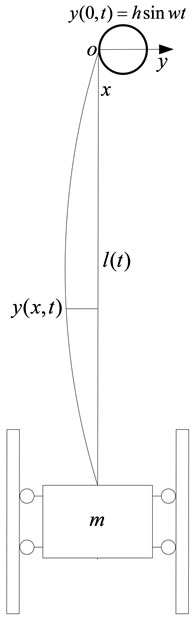
Suppose one position of the tension of wire rope is , the mass of wire rope per unit length is , the transverse vibration displacement of the wire rope is , and the excitation displacement at one end of the wire rope is . As can be seen from Fig. 1. The excitation is used to simulate the oscillation displacement of the head sheave.The mechanical model and coordinate of hoisting system established are as shown in Fig. 2. To establish the mathematical model of the hoisting system under external excitation, first the transverse vibration mechanical model of the wire rope of a small section of the wire rope is established, then the mathematical model of the transverse vibration of the wire rope can be deduced by Newton law of motion. Finally, the mathematical model of the hoisting system is acquired and is shown as:
In Eq. (1), , represents the amplitude of the external excitation, represents the frequency of the external excitation.
To simplify Eq. (1), set: , then Eq. (1) can be transferred to a new equation as below:
Fig. 1Swing of the wheel
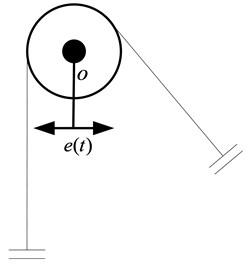
Fig. 2Model of hoisting system
3. Solution of the mathematical model
Since the problem for the partial differential equation is a problem with inhomogeneous boundary condition, so it is necessary to homogenize the boundary condition.
Set and . Then the problem with inhomogeneous boundary condition can be transferred to a problem with homogeneous boundary condition. The transferred problem is listed as:
Meanwhile:
Then needs to be determined. From the Eq. (4), we can know that pass through point and , so we can assume that it is a line passing through the two points on plane .
In order to get the expression of , set , then the following equations can be acquired:
So the following expressions can be obtained:
Finally, the expression of can be deduced:
Since the transverse vibration equation of wire rope is a partial differential equation with infinite freedom, it is difficult to acquire the exact analytical solution. Therefore, the numerical solution is adopted to approach the real solution, then the transverse vibration displacement of the wire rope is obtained. Among the methods of numerical solution, Galerkin method can be used to approach the real solution by the combination of a series of functions that are the product of spatial function and time function, and then the problem of partial differential equation of infinite dimensions can be converted into the ordinary differential equation of finite dimensions, so the problem of partial differential equation can be solved.
Since one of the boundary conditions of Eq. (3) is a time varying boundary condition, the variable field of in Eq. (3) needs to be transformed into a fixed field of in order to solve the partial differential equation. So the following conversion can be used to achieve the purpose:
With Eq. (8), .
So, can be expressed as following:
Among Eq. (9):
Then the following expression can be got:
Meanwhile:
Then the following expression can be obtained:
Substitute Eq. (11) and Eq. (13) into Eq. (3), so Eq. (3) can be converted to the Eq. (14) as following:
Within the Eq. (14):
And in Eq. (15):
Then multiplying both sides of Eq. (14) by and integrating both sides over [0, 1], so Eq. (14) can be expressed as the following equation:
And within Eq. (17), the following expressions can be obtained:
And , .
And then by integrating, each element of mass matrix, damping matrix and stiffness matrix can be calculated as following:
Among Eq. (20), the following expression is calculated in advance:
And also, the following expression can be acquired:
Within Eq. (22), the following expressions are calculated in advance:
At last, the elements of force matrix can be calculated as below:
Among Eq. (26), the following expressions are calculated in advance:
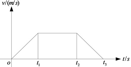
Then the velocity of the head sheave needs to be input. So let the velocity of wire rope changes over time as following as shown in Fig. 3.
Fig. 3Velocity of wire rope in hoisting system
And during the hoisting process, the initial length of is 1000 m.
And then the Eq. (17) can further be converted to facilitate calculation. The conversion is deduced as below.
In set then So the following expression can be acquired:
And the matrix can be defined as below:
Then a new equation can be acquired as following:
Therefore, the problem of partial differential equation is transformed into the problem of ordinary differential equation, and then it can be solved by numerical method.
4. Numerical result analysis
The parameters of hoisting system are shown in the Table.1.
Table 1Hoisting system parameters
Variable | Value |
Initial length of wire rope | 1000 m |
Mass of mass block | 25000 kg |
Acceleration of gravity | 9.8 m/s2 |
Mass of wire rope unit length | 1.5 kg |
Time | 2 s |
Time | 18 s |
Time | 20 s |
Acceleration of hoisting system | 1 m/s2 |
Amplitude of sine excitation | 0.002 m |
Frequency of sine excitation | 10 rad/s |
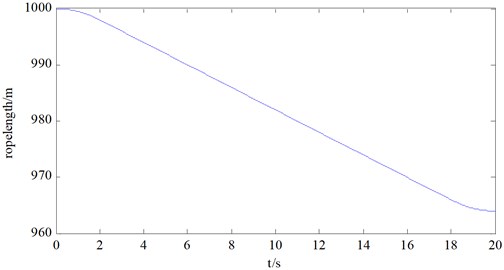
And the length of vertical section of wire rope changes as following as shown in Fig. 4. And the distance the wire rope moves is 36 m.
Fig. 4The length of vertical section of wire rope
Thus, the transverse vibration displacement of wire rope of the hoisting system at different positions can be acquired by solving Eq. (31). Choosing the position of 200 m away from the origin of the coordinate of the wire rope as the measuring point, then the transverse displacement, velocity and acceleration of the point can be got. The results are shown in Fig. 5, Fig. 6 and Fig. 7.
Fig. 5Transverse vibration displacement of wire rope at 200 m position
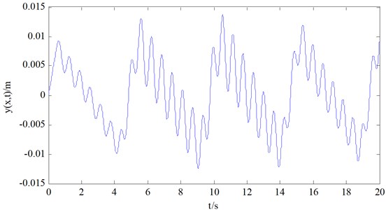
Fig. 6Transverse vibration velocity of wire rope at 200 m position
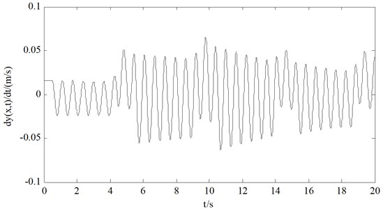
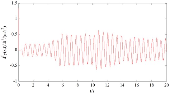
It can be seen from Fig. 5, Fig. 6 and Fig. 7, under the excitation at one end of the wire rope with amplitude of 0.002 m and frequency of 10 Hz, the transverse vibration displacement of the wire rope at position of 200 m is between –0.015 m and 0.015 m, the transverse vibration velocity is between –0.05 m/s and 0.05 m/s, and the transverse vibration acceleration is between –0.5 m/s2 to 0.5 m/s2.
Fig. 7Transverse vibration acceleration of wire rope at 200 m position
5. Factors influencing the vibration
In order to study the influence of different factors on the vibration characteristics of the hoisting system, the influences of loads, hoisting accelerations, mass of wire rope per unit length and external vibration frequency on the transverse vibration displacement of the wire rope are investigated, and the results are found as follows.
Fig. 8Transverse vibration displacement of wire rope under different loads
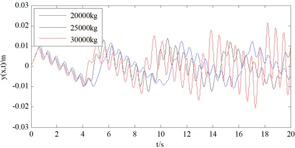
Fig. 9Transverse vibration displacement of wire rope under different hoisting accelerations
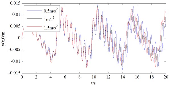
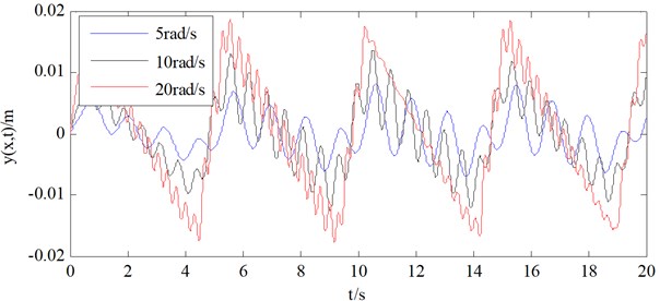
It can be seen from Fig. 8 and Fig. 9 as well as Fig. 10 that different loads, accelerations and mass of wire rope per unit length have little influence on the transverse vibration displacement of the wire rope. And as can be seen from Fig. 11, different external excitation frequency have an impact on the transverse vibration displacement of the wire rope, and with the increase of external excitation frequency, the transverse vibration displacement of the wire rope also increases. Therefore, in order to control the transverse vibration displacement of wire rope of the hoisting system, it can be considered from the aspect of controlling the external excitation frequency.
Fig. 10Transverse vibration displacement of wire rope under different mass of wire rope per unit length
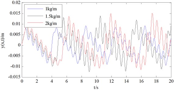
Fig. 11Transverse vibration displacement of wire rope under different external vibration frequency
6. Vibration energy analysis
In order to get the overall characteristics of the transverse vibration, the transverse vibration energy of wire rope in deep mining hoisting system is analyzed. The calculation formula of the transverse vibration energy is as following:
In order to calculate the transverse vibration energy, it is necessary to calculate the transverse vibration velocity of each point of the wire rope. For this purpose, first calculating the velocity of the wire rope at 300 m and 400 m primarily. The calculation formula is as below:
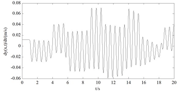
Thus, the velocity of the wire rope at two positions can be obtained, as are shown in Fig. 12 and Fig. 13.
Fig. 12The transverse vibration velocity of the wire rope at 300 m
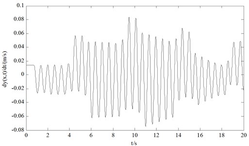
Fig. 13The transverse vibration velocity of the wire rope at 400 m
Then, by calculating the velocity of each point of the wire rope, the energy of the whole wire rope can be obtained, and the result is shown as Fig. 14.
Fig. 14The transverse vibration energy of the wire rope of whole length
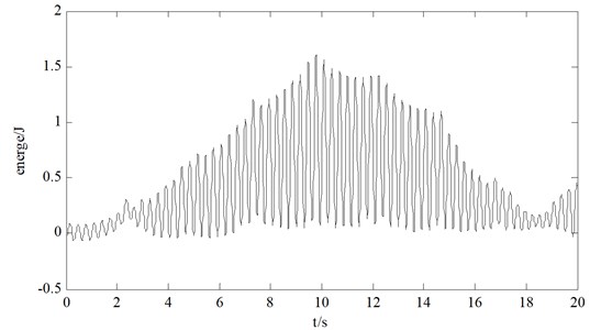
As can be seen from Fig. 12 and Fig. 13, the transverse vibration velocity of the wire rope is mainly between –0.1 m/s to 0.1 m/s. And as can be seen from Fig. 14, the energy of the wire rope of whole length is mainly between 0 J to 1.5 J, and the maximum energy appears at the middle time of operating process. Also, the vibration energy is relatively low at start time and end time. That is because the velocity is relatively low at both time.
7. Frequency analysis
In order to further analyze the dynamic characteristics of the system, frequency analysis of the system is required. In order to get the frequency of the system, first the frequency equation of the system is needed. For a general vibration system, the frequency equation is the characteristic equation of the vibration system, and the specific equation is as:
In Eq. (34), and are the mass matrix and stiffness matrix in Eq. (17), and is the natural frequency of the hoisting system,which is required to be calculated. Meanwhile, since the partial differential equation Eq. (3) with infinite degrees of freedom is transformed into ordinary differential equation Eq. (17) with finite degrees of freedom, so the equation also has finite natural frequencies. Finally, in order to solve the ordinary differential equation Eq. (17), the combinations of 30 linearly independent functions are used to approach the real solution, so the ordinary differential equation also has 30 degrees of freedom, which means the hoisting system have 30 modes and 30 natural frequencies accordingly.
Since the mass matrix and the stiffness matrix are time varying matrixes, the state of the hoisting system corresponding to a specific moment is selected for analysis. The state of hoisting system at 10 s is selected for analysis. The analysis results are shown in the following table.
Table 2The first 30 order transverse vibration frequencies of the wire rope of the hoisting system
Order | Frequency | Order | Frequency |
1 | 28.441 | 16 | 34.905 |
2 | 27.149 | 17 | 2.586 |
3 | 37.492 | 18 | 1.293 |
4 | 20.685 | 19 | 15.513 |
5 | 11.635 | 20 | 12.928 |
6 | 33.612 | 21 | 10.342 |
7 | 14.221 | 22 | 6.464 |
8 | 3.878 | 23 | 18.099 |
9 | 31.027 | 24 | 24.563 |
10 | 25.856 | 25 | 7.757 |
11 | 19.392 | 26 | 36.198 |
12 | 9.050 | 27 | 5.171 |
13 | 38.827 | 28 | 32.320 |
14 | 29.734 | 29 | 16.806 |
15 | 21.977 | 30 | 23.270 |
It can be seen from the table above that the vibration frequencies of the wire rope are mainly concentrated at 20 rad/s to 30 rad/s, so the closer the external vibration frequency is approaching this frequency range, the greater the transverse vibration displacement of the wire rope of the hoisting system will be. At the same time, when the hoisting system reaches a certain order of natural frequency, the hoisting system appears the phenomenon of resonance, and the transverse vibration displacement of the wire rope reaches the maximum value.
8. Experimental verification
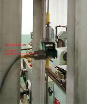
In order to further verify the validity of the mathematical model and the rationality of the data obtained, a test bench was established to measure the experimental data of the similar model. The position of 0.2 m away from the near end of the wire rope was selected as the measuring point to measure the transverse vibration acceleration of the wire rope during the hoisting process of the hoisting system. The results obtained from the experiment was used to make comparison with the results of numerical simulation obtained by the mathematical model, which was used to verify the rationality of the mathematical model that have been established.
The test bench is composed of motor, PLC, drum, wire rope, head sheave, mass block, guide rail and supporting bracket, as are shown in Fig. 15. The signal acquisition equipment of the vibration test system adopts acceleration sensor and is fixed on the measuring point of the wire rope, as is shown in Fig. 16. And in order to realize the purpose of applying external excitation on the wire rope, the head sheave is designed to be an eccentric wheel.
The parameters of the test hoisting system is listed in Table 3.
Table 3Parameters of the test hoisting system
Variable | Value |
Initial length of wire rope | 1.8 m |
Radius of drum | 0.03 m |
Radius of head sheave | 0.03 m |
Mass of mass block | 0.5 kg |
Hoisting velocity | 0.12 m/s |
Amplitude of sine excitation | 0.002 m |
Time | 10 s |
Fig. 15The testing hoisting system
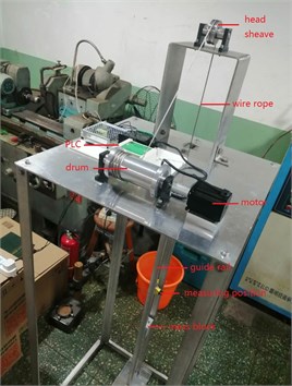
Fig. 16The acceleration sensor
Through the experiment, the transverse vibration acceleration at 0.2 m of the wire rope can be obtained, as is shown in Fig. 17. And the data from 0 to 1s is ignored because the state of data collection was unstable during the station.
Fig. 17The test acceleration of wire rope of the test bench
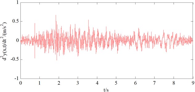
Fig. 18Comparison of acceleration between numerical results and experimental results
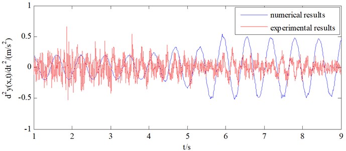
And the comparison of acceleration between numerical results and experimental results can be made, as was shown in Fig. 18. And from Fig. 18, it can be seen that the acceleration of numerical results and experimental results are basically range from –0.5 m/s2 to 0.5 m/s2. And it can be found that the two results are overall similar, which reflects the validity of the mathematical model.
9. Conclusions
In this paper, the transverse vibration mathematical model of wire rope in deep mining hoisting system is established, and the problem of partial differential equation with infinite dimension is converted into the problem of ordinary differential equation with finite dimension by Galerkin discrete method. Finally, the numerical solution results of the transverse vibration of wire rope is acquired, and the experiment is designed to verify the validity of the mathematical model. The conclusions are as below.
1) The transverse vibration mathematical model of wire rope in deep mining hoisting system is established and solved by Galerkin discrete method.
2) Under the excitation at one end of the wire rope with amplitude of 0.002 m and frequency of 10 Hz, the transverse vibration displacement of the wire rope at position of 200 m is between –0.015 m and 0.015 m, the transverse vibration velocity is between –0.05 m/s and 0.05 m/s, and the transverse vibration acceleration is between –0.5 m/s2 to 0.5 m/s2.
3) Different loads, accelerations and mass of wire rope per unit length have little influence on the transverse vibration displacement of the wire rope, but different external excitation frequency have an impact on the transverse vibration displacement of the wire rope. And with the increase of external excitation frequency, the transverse vibration displacement of the wire rope also increases.
4) The energy of the wire rope of whole length is mainly between 0 J to 1.5 J, and the maximum energy appears at the middle time of operating process.
5) The vibration frequencies of the wire rope are mainly concentrated at 20 rad/s to 30 rad/s, so the closer the external vibration frequency is approaching this frequency range, the greater the transverse vibration displacement of the wire rope of the hoisting system will be.
6) The experiment of the hoisting system is established to verify the validity of the mathematical model. And the acceleration of numerical results and experimental results are basically range from –0.5 m/s2 to 0.5 m/s2, and also the two results are overall similar, which reflects the validity of the mathematical model.
References
-
Bao Ji Hu, Zhang Peng, Zhu Chang Ming Modeling and analysis of rope transverse vibration for flexible hoisting systems with time varying length. Journal of Shanghai Jiaotong University (Science), Vol. 46, Issue 3, 2012, p. 341-345.
-
Bao J. H., Zhang P., Zhu C. M. Dynamic Analysis of Flexible Hoisting Rope with Time-Varying Length. International Applied Mechanics, Vol. 51, Issue 6, 2015, p. 710-720.
-
Zhang Peng, Zhu Chang-Ming, Zhang Liang-Juan Analysis of forced coupled longitudinal transverse vibration of flexible hoisting systems with varying length. Journal of Engineering Mechanics, Vol. 25, Issue 12, 2008, p. 202-207.
-
Wu Juan, Kou Ziming, Liang Min, Wu Guoxiong Analysis and experiment of rope transverse vibration for multi-rope friction hoisting system. Journal of Huazhong University of Science and Technology (Nature Science Edition), Vol. 6, Issue 12, 2015, p. 16-21.
-
Wu Juan, Kou Ziming Theoretical coupling longitudinal-transverse model and experimental verification of transverse vibration of rope for multi-rope friction hoisting system. International Journal of Coal Science and Technology, Vol. 3, Issue 1, 2016, p. 77-84.
-
Kou Baofu, Liu Qiuzu, Liu Chunyang, et al. Characteristic research on the transverse vibrations of wire rope during the operation of mine flexible hoisting system. Journal of China Coal Society, Vol. 40, Issue 5, 2015, p. 1194-1198.
-
Qi X., Zhang R., He Q. Modeling and analysis of transverse vibration of traction rope of high speed traction elevator. IOP Conference Series Materials Science and Engineering, Vol. 538, 2019, p. 12-36.
-
Zhu W. D., Ni J. Energetics and stability of translating media with an arbitrarily varying length. Journal of Vibration and Acoustics, Vol. 122, Issue 7, 2000, p. 295-304.
-
Zhu W. D., Chen Y. Forced response of translating media with variable length and tension: application to high-speed elevators. Journal of Multibody Dynamics, Vol. 219, Issue 1, 2005, p. 35-53.
-
Zhu W. D., Xu G. Y. Vibration of elevator cables with small bending stiffness. Journal of Sound and Vibration, Vol. 263, Issue 3, 2003, p. 679-699.
-
Lee S. Y., Lee M. A New wave technique for free vibration of a string with time-varying length. Journal of Applied Mechanics, Vol. 69, Issue 1, 2002, p. 83-87.
-
Cooper J. Asymptotic behavior for the vibrating string with a moving boundary. Journal of Mathematical Analysis and Applications, Vol. 174, Issue 1, 1993, p. 67-87.
-
Balazs N. L. On the solution of the wave equation with moving boundaries. Journal of Mathematical Analysis and Applications, Vol. 3, Issue 3, 1968, p. 472-484.
-
Terumichi Y., Ohtsuka M., Yoshizawa M. Nonstationary vibrations of a string with time-varying length and a mass-spring system attached at the lower end. Nonlinear Dynamics, Vol. 30, Issue 12, 1997, p. 39-55.
-
Zhang C. Y., Zhu C. M., Lin Z. Q. Theoretical and experimental study on the parametrically excited vibration of mass-load string. Nonlinear Dynamics, Vol. 37, Issue 1, 2004, p. 1-18.
-
Kimura H., Iijima T., Matsuo S., et al. Vibration analysis of elevator rope. Journal of System Design and Dynamics, Vol. 3, Issue 3, 2009, p. 420-428.
-
Otsuki Masatsugu, Yoshida Kazuo, Nakagawa Toshiaki, Kimura Hiroyuki, Fujimoto Shigeru Nonstationary robust control for vibration of elevator-rope. Transactions of the Japan Society of Mechanical Engineers, Vol. 71, Issue 703, 2005, p. 859-866.
-
Wang L. H., Hu Z. D., Zhong Z., et al. Dynamic analysis of an axially translating viscoelastic beam with an arbitrarily varying length. Acta Mechanica, Vol. 214, Issues 3-4, 2010, p. 225-244.
-
Sandilo S. H., Van Horssen W. T. On variable length induced vibrations of a vertical string. Journal of Sound and Vibration, Vol. 333, Issue 11, 2014, p. 2432-2449.
-
Perov P., Johnson W., Perova Mello N. The physics of guitar string vibrations. American Journal of Physics, Vol. 84, Issue 1, 2016, p. 38-43.
-
Vesnitskii A. I., Potapov A. I. Some general properties of wave processes in one-dimensional mechanical systems of variable length. Soviet Applied Mechanics, Vol. 11, Issue 4, 1975, p. 422-426.
-
Ostrovskiǐ L. A. Some general relations for waves at the moving boundary between two media. Journal of Experimental and Theoretical Physics, Vol. 34, 1972, p. 293.
-
Morino L., Bharadvaj B. K., Freedman M. I., Tseng K. Boundary integral equation for wave equation with moving boundary and applications to compressible potential aerodynamics of airplanes and helicopters. Computational Mechanics, Vol. 4, Issue 4, 1989, p. 231-243.
Cited by
About this article

