Abstract
In order to reduce load impact and hydraulic leakage happened in the process of locked rope switching or stroke arrival for the present rope changing devices, a novel type of rope changing device with clamping chain transmission is designed based on the “pipe forming mechanism”. The new device fundamentally improves the safety and stability of steel-rope. By theoretical deduction, the steel-rope transverse vibrations in rope changing of the new device are calculated. Results show that the compacting force of locked-rope mechanism can reduce the transverse vibration amplitude by 80 % or more, which is caused by the polygon effect in chain transmission; as the increasing rigidity of locking disc spring, the limitation for transverse vibration displacement of wire rope becomes stronger, and the effect is fading when the rigidity reaches a certain value. Transverse vibration trends of steel-rope from test are consistent with the theoretical calculation results, which verify the correctness of the theoretical calculation; The maximum vibration amplitude of steel-rope is less than 0.4mm, effectively limiting the transverse vibration caused by the polygon effect in chain transmission and making the steel-rope work continuously and smoothly.
1. Introduction
Increasing exhaustion of shallow resources brings great growth of large-scale 1000-plus deep mines. Lifting steel-rope with larger diameter and self-weight, together with more complicated load impacts in internal torsion, bending and stretching applied in deep mines draws higher requirements for security in rope changing [1-3]. Commonly-used auxiliary tool-chain block can’t apply to such heavy-load conditions [4-8]. A series of studies on rope changer have solved the problems of lager-diameter rope changing in heavy-load conditions, however hydraulic leakage, seal-aging and joint line breakage still lead to security risks due to the long duration working mode of its hydraulic power mechanism. Furthermore, the transverse vibration caused by stroke arrival of hydraulic cylinder and repeated rope switching results in serious problems, i.e. “rope slipping”, “rope twisting” or “rope skipping” in lifting steel-rope changing, which sometimes bring about catastrophe failure [9-12]. In order to find a solution for the existing problem in rope changer, this study has found a kind of rope changer with double-chain transmission based on the “pipe forming mechanism”.
Since steel-rope vibration may cause load fluctuation, bounce, impact and bring about accidents, these studies on steel-rope vibration have attracted many scholars and they have made quite gratifying achievements in both theoretical derivation and experimental tests. Shi-Rong Yan [13] has conducted modeling calculation for the deformation of steel-rope in downward movement and analyzed the influence of variable stiffness and mass on steel-rope vibration. Guo-Hua Cao [14] has conducted modeling calculation considering the impact of variable stiffness effect on steel-rope in the loading process and analyzed vibration characteristics of skip loading and cage. Yu-Qiang Jiang [15] has established the coupling dynamics model for hoisting system of the flexible space 6 degree of freedom and studied the nonlinear coupling characteristics of cage. On the basis of previous studies, calculation of steel-rope transverse vibration in rope changing of rope changer with clamping chain transmission and experimental tests have been conducted in this paper.
2. Rope changer with clamping chain transmission
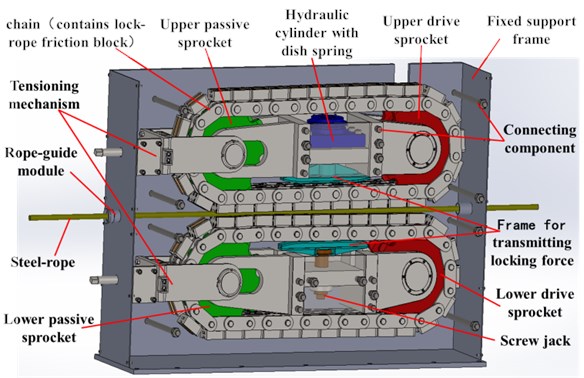
As is shown in Fig. 1, rope changer with clamping chain transmission comprises two groups of transmission chains, two groups of driving chain wheels, two groups of driven chain wheels, disc spring hydraulic cylinder, screw jack, force transmission frame, chain tension mechanism, fixing racks, rope guide module and connectors. Two groups of transmission chains and wheels can achieve rope receiving and releasing; disc spring hydraulic cylinder, screw jack and force transmission frame constitute the locking module, applying the working mode of “loosening rope by hydraulic pressure and locking rope by resetting the disc spring”; chain tension mechanism provides stable tension for chains by “threaded adjusting and locking”.
Rope changer with clamping chain transmission device achieves rope receiving and releasing based on “pipe forming mechanism”. As is seen in Fig. 1, driving chain wheels put two groups of chains in circulatory motion under the drive of “frequency conversion brake motor decelerator”; the horizontal chain in the middle drives the lifting steel-rope to make linear motion forward or backward, transforming circular motion of chain wheels into continuous linear motion of lifting rope, and motions of rope receiving and releasing keep going without interruption. Screw jack and disc spring hydraulic cylinder make groove with wheels in chains press lifting steel-rope tight and provide stable and reliable rope locking power by thrust frame. Chain tension is adjusted by pulling the connecting shaft of driven chain wheel with tension mechanism.
Fig. 1Structural diagram of rope changer with chain transmission
The device achieves continuous non-stop change of lifting steel-rope, avoiding stroke arrival of rope releasing mechanism and impact of load vibration caused by repeated switching between rope locking and loosening, and improves the efficiency of rope changing. Start and stop of the device are controlled by frequency conversion and rope changer runs more smoothly. Though the rope changer has fundamentally improved security and stability of rope changing devices, chain transmission with polygon effect still brings transverse vibration. Thus, the study on transverse vibration characteristics of the new device will help to understand vibration rule and optimize its functions.
3. Vibration model
3.1. Model analysis
In order to make deep analysis of its vibration characteristics, the device is simplified as theoretical model. Since clamping force of twin rope is achieved by reset force of disc string, the contact point of thrust frame and groove roller in the chain can be simplified as an elastic support; lifting steel-rope is located in the middle of two symmetrical chains and a group of chains is chosen as object of study to show vibration of lifting steel-rope in receiving and releasing [16-20]. Simplified model is shown in Fig. 2.
Fig. 2Dynamics model of transverse vibration with clamping chain transmission
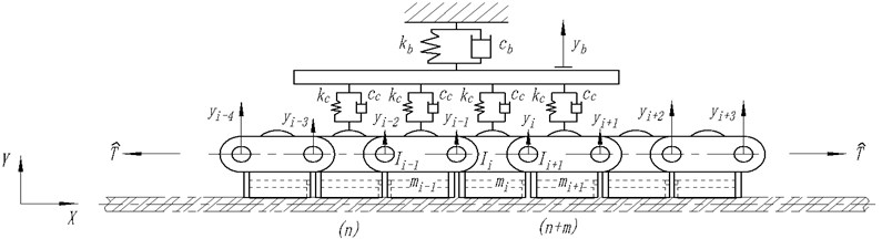
For the convenience of theoretical analysis to grasp vibration rules of steel-rope in rope changing, here several hypotheses are made: (1) tension between chain links is equal; (2) vibration appears only in the plane of the chain wheel; (3) with its mass ignored, steel-rope vibrates together with the vibration of the compacted chain in the whole process; (4) mass, pitch and moment of inertia for each chain link are equal; (5) disc spring hydraulic cylinder is simplified as an elastic supporting module.
1) System kinetic energy analysis
Assumed that the center of gravity of chain link is its geometric center, then the chain link lateral displacement deviate from the equilibrium position can be expressed as:
where and are lateral displacement of hinge centers at both ends of chain link .
Because that the chain contact with the wire rope around its geometric center angle is very small, the rotation angle of chain can be represented by the lateral displacement of both ends of the hinge:
where is hinge pitch; is the rotation angle of chain .
By the Eq. (1) and (2), the chain link speed of its center of gravity in the direction can be obtained as:
where is longitudinal velocity; The second term of the above formula is the transverse velocity component of the chain caused by the longitudinal velocity of the chain.
According to Eq. (2), the rotation speed of chain link around its geometric center can be obtained as:
The chain link is approximately regarded as the rod around its rotation center in the calculation of inertia moment of link, the moment of inertia can be expressed as:
where is mass of chain link ; is moment of inertia of chain link .
According to mechanical analysis of the model, and by combining Eq. (3), (4) and (5), kinetic energy of the system can be obtained as:
where is mass of force transmission frame; and is transverse vibration displacement of guide rail.
2) System potential energy analysis
The system potential energy includes the following three parts: the potential energy caused by the chain itself; the potential energy is the contact between link and rope locking force transmitting frame; third potential energy caused by the spring stiffness of the lock rope thrust frame. The first part of the potential energy is analyzed as follows.
In the transmission process, both ends of the drive chain are affected by the centrifugal tension except for the initial static tension . Therefore, the total dynamic tension at both ends of the transmission chain can be expressed as:
where is mass per unit length of chain link; is tension on both ends of the chain.
Fig. 3Diagrammatic sketch of chain stiffness analysis
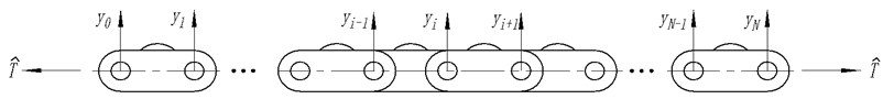
a) Transverse equilibrium state of the chain link
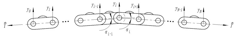
b) New equilibrium state of the chain under transverse force
As shown in Fig. 3(a), the chain link with the effect of tension will show the level position balance under the condition of the chain weight is relatively small and can be neglected. If the chain link is applied on a vertical upward force , as shown in Fig. 3(b), the hinge center of the chain link will produce a lateral displacement. A new equilibrium is obtained:
where and are the angle between the horizontal line and the connection chain link hinge center.
As shown in Fig. 3(b) shows, this angle can be expressed as follows by displacement :
Putting Eq. (9) into Eq. (8) brings the following result:
According to the Eq. (10), both 0 and can be drawn as follows:
According to the Eq. (10) and Eq. (11), the following conclusions can be drawn:
Eq. (12) is changed into matrix form:
where is ; is ; is the chain link lateral static stiffness matrix.
The chain link lateral static stiffness matrix is as follows:
The potential energy caused by the chain itself can be expressed as:
Putting Eq. (14) into Eq. (15) brings the following expression:
Potential energy of the system is:
where shows serial number of the first chain link contacting thrust frame; shows amount of all chain links contacting thrust frame; is contact stiffness between chain link and force transmission frame; and is spring stiffness in clamping the thrust frame.
3) System dissipation energy analysis
The system dissipation energy includes the following three parts: the dissipation energy caused by viscous damping between the chain links; the dissipation energy is the contact damping between link and rope locking force transmitting frame; third potential energy caused by the spring damping of the lock rope thrust frame.
The dissipation energy caused by viscous damping between the chain links can be expressed as:
Dissipated energy of the system is:
where is viscous damping between chain links; is viscous damping between chain link and guide rail; and is viscous damping between guide rail and tight spring.
Putting the three formulas above into Lagrange equation brings the following result:
where is generalized coordinates; and isgeneralized force.
Transverse vibration dynamics equation of chain transmission system can be got by applying Lagrange equation as:
where , , , and are listed in Appendix.
3.2. Simulation analysis
A rope changer with chain transmission has been designed according to the load case of one vertical shaft lifting steel-rope with its relevant parameter shown in Table 1. Transverse vibration rule of the rope changer has been found with MATLAB simulation analysis.
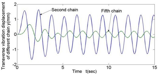
There are 11 horizontal chain links in total and chain links from the fifth to the eighth are clamped tightly and contacts with the steel-rope. In the model, all damping coefficients are set as 0.03 equally. According to preliminary design, disc spring stiffness is 107N/m. Since the lifting steel-rope contacts the chain link tightly-clamped by thrust frame in rope changing, transverse vibration of the lifting steel-rope is just identical to that of the tightly-clamped chain link. To analyze transverse vibration of different chain links at each moment, data of the representative second and fifth chain links are loaded, and chain link vibration displacements with chain link linear velocity equal to 0.43 and 0.215 are shown in Fig. 4 and Fig. 5.
Table 1Parameter table of rope changer with chain transmission
Parameter | Chain pitch / mm | Mass of chain link / kg | Moment inertia of chain link / kg·m2 | Amount of horizontal chain links | Mass of thrust frame / kg | Tension / kN | Velocity / ms-1 |
Value | 150.12 | 15.26 | 0.0286 | 11 | 76.3 | 50 | 0 – 0.43 |
Fig. 4Transverse vibration results of different chain links (v= 0.43 m/s)
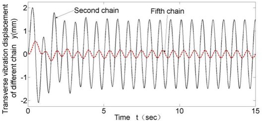
Fig. 5Transverse vibration results of different chain links (v= 0.215 m/s)
The key of the device lies in stability of lifting steel-rope running. Vibration of the rope is identical to that of the fifth chain link. In Fig. 6 shows the vibration displacements of lifting steel-rope of this rope changer with different running velocities.
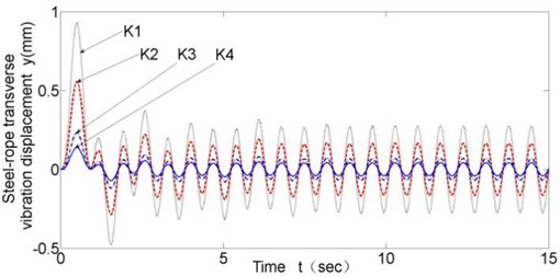
Fig. 7 show transverse l vibration results of the lifting steel-rope with different disc spring stiffness. To show the influence of the disc spring stiffness, spring stiffness - have been set as 106 N/m, 107 N/m, 5×10⁷ N/m, 108 N/m.
Following conclusions can be drawn through simulation: (1) Fig. 4 and Fig. 5 show that in all working conditions, compared with the second chain link with no clamping force from thrust frame, the fifth chain link tightly-clamped by thrust frame and contacting the lifting steel-rope has a smaller transverse vibration amplitude with a decrease of about 80 % in amplitude; and that proves that rope locking module plays a significant inhibitory effect on transverse vibration of steel-rope. (2) Decrease of rope changing velocity can slightly weaken transverse vibration of the steel-rope at low running velocity, yet the effect is quite small. (3) Disc spring stiffness coefficient has significant influence on transverse vibration amplitude of steel-rope, and transverse vibration amplitude decreases with increasing disc spring stiffness; however, after the stiffness reaches the value of K3 (5×10⁷ N/m), the limitation becomes insignificant.
Fig. 6Transverse vibration results of different running velocities
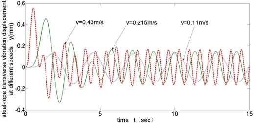
Fig. 7Transverse vibration results with different disc spring stiffness (v= 0.43 m/s)
4. Experimental study
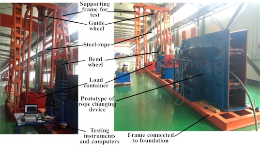
On the basis of above theoretical analysis and transverse vibration dynamic simulation, a rope changer prototype has been designed and made in accordance with actual parameters of lifting steel-rope in a mine with disc spring stiffness as 107N/m. To verify the performance of the device and correctness of theoretical analysis and calculation, a simulating platform of lifting system has been built.
Fig. 8 shows schematic diagram of test platform of the rope changer with clamping chain transmission. Test support frame welded by profile steel simulates lifting shaft, lifting load container simulates rope weight load, and test instruments are placed on the test support platform and all assembly units are fixed to foundation supporting structure with bolts.
A testing sensor ( direction) for transverse vibration of steel-rope is fixed on the rope to transfer real-time dynamic transverse vibration displacement of the rope to data acquisition instrument and record data with a computer.
Fig. 9 shows test site arrangement plan. The steel-rope keeps running in the experiment so repeated vibration tests are conducted. The vibration test data 5 seconds under normal running are chosen from exporting data and make a comparation to vibration simulation data with 10-15 s, which is stable and representative with MATLAB tools.
Fig. 8Schematic diagram of test platform of the rope changer with clamping chain transmission
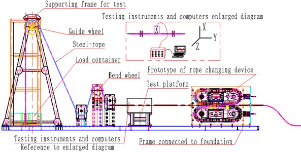
Fig. 9Test site map of steel-rope vibration experiment during rope changing
Comparisons of test and theoretical calculating values for steel-rope transverse vibration displacements with rope changing velocity as 0.43 m/s, 0.215 m/s and 0.11 m/s are shown respectively in Fig. 10 to Fig. 12.
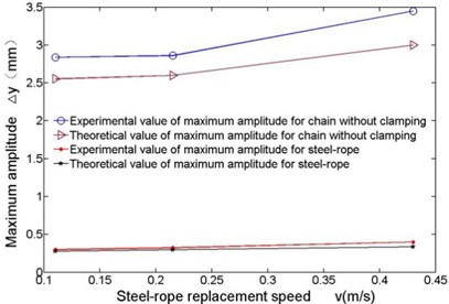
The maximum transverse vibration amplitude is a key indicator of security and stability of the device in rope changing. Data from Fig. 10 to Fig. 12 have been processed to show the change of maximum amplitudes of steel-rope and unclamped chain links at different velocities in Fig. 13.
Fig. 10Comparison of test and theoretical calculation of transverse vibration (v= 0.43 m/s)
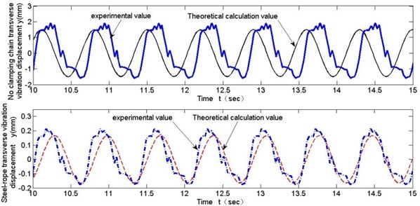
These experimental data contribute to following conclusions: (1) From Fig. 10 to Fig. 12, the general trend of transverse vibration of the steel-rope and unclamped chain links in the experiment is obtained, which is basically consistent with theoretical calculation, though larger vibration amplitude appearing partially at a certain moment due to other external reasons, which verifies the correctness of theoretical calculation. Moreover, maximum transverse amplitude is no greater than 0.4 mm in the whole experiment with different velocities of rope changing. (2) As is shown in Fig. 13, transverse vibration amplitude of the steel-rope slightly increases with increasing rope changing velocity, indicating rope changing velocity has comparatively less effect on transverse vibration of steel-rope at low velocities. (3) By comparison of the maximum amplitudes of unclamped chain links and steel-rope in Fig. 13, significant inhibitory effect of the locking module on transverse vibration of chain transmission can be shown, with amplitude decreasing rate at 80 %-90 %, and inhibitory effect becomes more obvious with the increase of rope changing velocity.
Fig. 11Comparison of test and theoretical calculation of transverse vibration (v= 0.215 m/s)
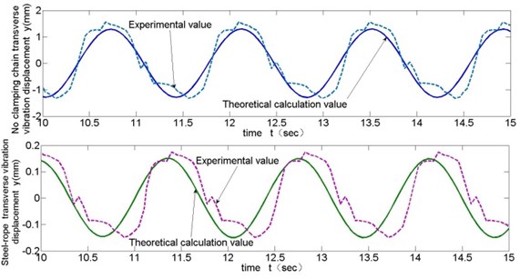
Fig. 12Comparison of test and theoretical calculation of transverse vibration (v= 0.11 m/s)
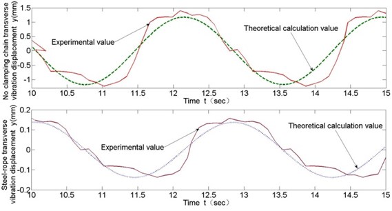
Fig. 13Comparison of the maximum amplitudes at different velocities
In brief, experimental results show the rope changer with clamping chain transmission constrains transverse vibration of the steel-rope caused by polygon effect of chain transmission and makes the rope run with greater security, continuity and stability.
5. Conclusions
1) Despite the inevitable existence of polygon effect in rope changer with chain transmission, adding compaction mechanism can decrease transverse vibration caused by this excitation significantly with a decrease of about 80 % in vibration amplitude.
2) For system parameters of the rope changer, transverse vibration amplitude can be effectively restrained by increasing disc spring stiffness whose value reaching 5×10⁷N/m can make the inhibitory effect tends. However low rope changing velocity have little influence on transverse vibration amplitude of steel-rope.
3) The general trend of transverse vibration of the steel-rope and unclamped chain links in the experiment are basically consistent with theoretical calculation, which verifies the correctness of theoretical calculation.
4) The conclusion of the study can be used for the continuous transportation and recovery of pipeline structure parts, especially can be used for pipeline parts driving in the heavy load conditions.
References
-
Jia Fuyin, Dong Mengjuan Stabilizing cage technology of deep shaft friction hoist. Journal of China Coal Society, Vol. 36, Issue 1, 2011, p. 177-180.
-
Wang Dagang, Zhang Dekun, Ge Shirong Effect of terminal mass on fretting and fatigue parameters of a hoisting rope during a lifting cycle in coal mine. Engineering Failure Analysis, Vol. 36, Issue 1, 2014, p. 407-422.
-
Guse A. J. High performance synthetic ropes for mine hoisting. SME Annual Meeting and Exhibit: Leadership in Uncertain Times, Salt Lake City, UT, United States, 2014, p. 494-498.
-
Li Tieping, Li Zhida, Chen Jianqiao, et al. Viscoelastic properties of fibre-core hoisting cable. Journal of Mechanical Strength, Vol. 26, Issue 3, 2004, p. 337-340.
-
Kou Baofu, Liu Qiuzu, Li Weihao, et al. Behavior analysis of wire-rope transverse vibration in the process of replace-rope of hoisting system. Journal of China Coal Society, Vol. 40, Issue 1, 2015, p. 247-251.
-
Peterka Pavel, Krešák Jozef, Kropuch Stanislav Failure analysis of hoisting steel wire rope. Engineering Failure Analysis, Vol. 45, Issue 11, 2014, p. 96-115.
-
Ma Kaicheng, Jia Fuyin, Dong Mengjuan, et al. Replacement method and safety analysis on first rope of mine shaft hoist. Coal Science and Technology, Vol. 39, Issues 9-73, 2011, p. 75-80.
-
Baofu Kou, Peng Fan The analysis of security wedge lock-rope mechanism by ANSYS finite element analysis. Applied Mechanics and Materials, Vols. 713-715, 2015, p. 107-113.
-
Niko Korkeakangas, Matti Hynni Method for Replacing the Hoisting Roping of an Elevator and a Traction Appliance Arrangement Used in the Replacement. US8112861, USA, 2008-11-10.
-
Gong Xuedong, Yao Huimiao, Zhang Min Simulation research on the rapid replacement device for host ropes of multi-rope friction hoist. Machine Tool and Hydraulics, Vol. 44, Issue 10, 2016, p. 26-28.
-
Singh M. K., Mahto A., Thakur R. N. Failure analysis of wire rope used for hoisting in mining: a case study. Journal of Failure Analysis and Prevention, Vol. 7, Issue 2, 2007, p. 87-91.
-
Guse, High A. J. Performance Synthetic Ropes for Mine Hoisting. SME Annual Meeting and Exhibit: Leadership in Uncertain Times, Salt Lake City, UT, United States, 2014, p. 494-498.
-
Yan Shirong, Wen Chenchun Dynamic simulation of hoisting wire rope in the lower container. Journal of China Coal Society, Vol. 23, Issue 5, 1998, p. 530-534.
-
Cao Guohua, Zhu Zhencai, Peng Weihong, et al. Coupled vibration of hoisting rope during tramcar pushing into or out cage in winding hoist system. Journal of China Coal Society, Vol. 34, Issue 5, 2009, p. 702-706.
-
Jiang Yuqiang Research on Nonlinear Coupling Characteristics and Condition Assessment of Vertical Steel Guide System. China University of Mining and Technology, Xu Zhou, 2011.
-
Chen L. Q., Yang X. D. Bifurcation and chaos of an axially accelerating viscoelastic beam. Chaos, Solitons and Fractals, Vol. 23, 2005, p. 249-258.
-
Zhang G. C., Ding H., Chen L. Q., Yang S. P. Galerkin method for steady-state response of nonlinear forced vibration of axially moving beams at supercritical speeds. Journal of Sound and Vibration, Vol. 331, 2012, p. 1612-1623.
-
Ghayesh M. H. Nonlinear forced dynamics of an axially moving viscoelastic beam with an internal resonance. International Journal of Mechanical Sciences, Vol. 53, 2011, p. 1022-1037.
-
Wang B. Asymptotic analysis on weakly forced vibration of an axially moving viscoelastic beam constituted by standard linear solid model. Applied Mathematics and Mechanics, Vol. 33, 2012, p. 771-780.
-
Duan Y. C., Wang J. P., Wang J. Q., Liu Y. W., Shao F. Theoretical and experimental study on the transverse vibration properties of an axially moving nested cantilever beam. Journal of Sound and Vibration, Vol. 333, 2014, p. 2885-2897.
About this article

The work described in this paper was supported by the Foundation of Scientific and Technological Innovation Research Projects in Universities of Shanxi, China (Grant No. 2016165); and the Scientific Research Foundation for the Doctors of Taiyuan University of Science and Technology, China (Grant No. 20152025).
