Abstract
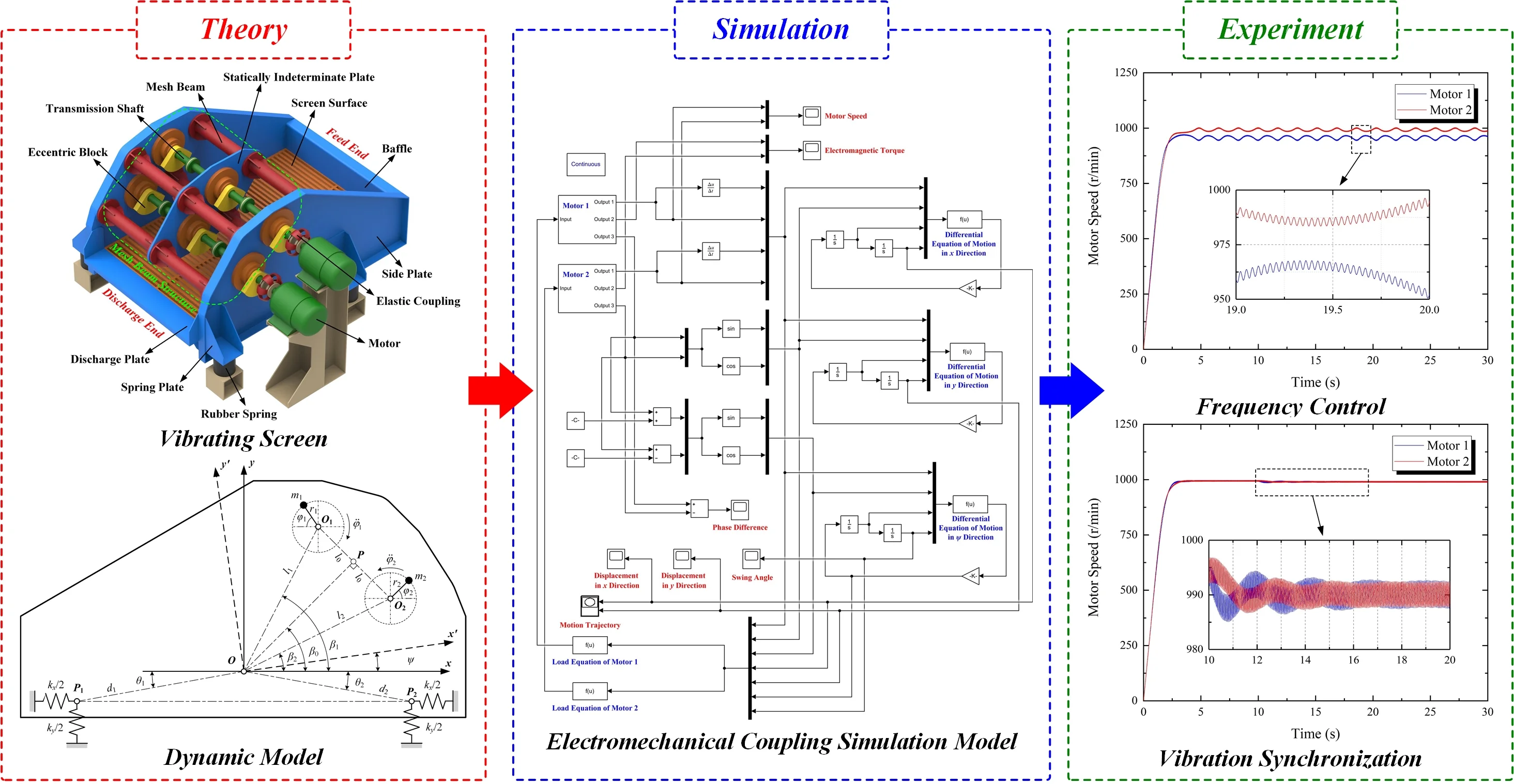
The vibrating screen with statically indeterminate mesh beam structure (VSSIMBS) is a novel type of large vibrating screen, which is widely used in coal preparation plants due to its high strength and processing capacity. In this study, the VSSIMBS motion differential equations were obtained via on Lagrange equation, and the dynamic vibration system model was established. The eccentric block force conditions during the operation were analyzed, and the stable vibrating screen operational conditions were obtained. The electromechanical coupling simulation model of VSSIMBS was built in Simulink, allowing frequency control and vibration synchronization experiments. Experimental frequency control results have shown that when the output characteristics of both motors are either the same or similar, synchronous movement can be achieved. Regarding vibration synchronization, experiment results have shown that when two motors are in synchronous motion, and the power supply of one motor is cut off, they still can operate synchronously. Thus, the experimental results obtained in this study provide a theoretical reference for improving the motion stability of large vibrating screens.
Highlights
- Dynamic theoretical model and electromechanical coupling simulation model of vibrating screen with were established
- Influences of motor output characteristics on operation stability of vibrating screen were researched
- Results indicate motor speed difference and sudden power failure cannot affect synchronous motion
1. Introduction
Coal is the primary energy source used in China, which has abundant reserves totaling 5.9 trillion tons [1]. Thus, it is the most cost-effective, reliable, and rudimentary guarantee for Chinese energy security – a base of its energy strategy. In 2020, Chinese raw coal output was 3.9 billion tons, with a year-on-year growth of 1.4 %, and coal consumption accounted for 56.8 % of the total energy consumption [2]. Chinese energy characteristics are as follows – it is coal-rich and has a low amount of oil and gas, which further cements coal as the main energy source. Thus, a significant change in China is not expected in the near future [3].
Furthermore, coal has significantly contributed to the development of the Chinese national economy; however, it also caused serious environmental pollution. Currently, the clean utilization degree of coal in China is relatively low. The raw coal proportion is approx. 59 %, while in developed countries, it is roughly 80 %. Therefore, coal’s efficient and clean utilization is imminent [4].
Coal preparation is the basis and premise for the clean utilization, energy conservation, and sustainable development of coal; it is the most economical and effective clean coal technology [5]. The vibrating screen is a piece of key equipment for coal preparation and is widely used in raw coal classification. The number of large-scale coal mines is increasing with the adjustment of the coal industry structure and the reorganization of coal enterprises [6]. Hence, the demand for large vibrating screens is increasing day by day. Large vibrating screens can simplify the coal preparation process and reduce basic investment. For this reason, they have become the main trend in developing vibration screening equipment [7].
For large vibrating screens, due to the notable screen body mass, a single driving motor cannot meet the working requirements; therefore, generally, two or more motors are used simultaneously. Motors must maintain the same speed and phase to ensure stable vibrating screen operation [8]. In vibration machinery, eccentric rotors driven by motors are used to transfer the energy and motion necessary to achieve synchronous rotation. The vibration synchronization theory makes the vibrating screen structure simple and reasonable, reducing the manufacturing cost. As such, it is widely used in vibrating machinery design and manufacture [9].
Fig. 1Structure of VSSIMBS
The vibration synchronization phenomenon was first discovered by Huygens [10]. Blekhman studied the stability of synchronous motion in double eccentric rotors using the Poincare-Lyapunov small parameter [11, 12]. Moreover, Balthazar et al. observed the self-synchronization mechanism near the resonance of non-ideal exciters via numerical simulations [13, 14]. Nijmeijer reviewed the synchronization of complex systems from a dynamic control perspective [15]. Next, Fradkov et al. proposed the dynamic control synchronization strategy based on exciter vibration synchronization [16, 17]. Yamapi et al. considered the self-synchronization dynamics of electromechanical coupling devices [18, 19], while Perlikowski et al. studied the 1:1 mode-locking and generalized synchronization in mechanical oscillators. Czołczynski et al. researched the synchronization of self-excited oscillators suspended on elastic structures [20, 21]. Domestic scholars have also carried out many studies on vibration synchronization. Wen et al. systematically studied the vibration system synchronization theory, obtaining both the synchronization and stability criteria of the synchronization state while considering the vibration system damping [22, 23]. Zhao et al. proposed a synchronization mechanism consisting of two different vibration exciters. The design was theoretically and numerically studied based on internal motor characteristics [24, 25]. Zhang et al. established a set of systematic theoretical systems and framework of vibration synchronization, and also proposed the synchronization and stability criteria for the multi-motor driving system [26, 27]. Peng et al. investigated the stability and synchronization conditions of the anti-resonance system with three exciters and a secondary vibration isolation system with two exciters [28, 29]. Finally, Zou et al. studied the multiple-frequency synchronization of two vibrating motors and proposed a controlled system for two eccentric rotors actuated with a double-frequency [30, 31]. The scholars mentioned above at home and abroad have conducted many investigations regarding the problem of multiple motors’ synchronous motion of vibrating screens via theoretical modeling, simulation analysis, and vibration testing. Their theories and methods provide a reference for the dynamic characteristics analysis of the novel vibrating screen.
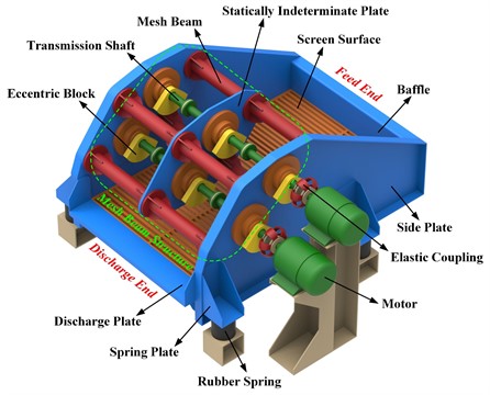
The vibrating screen with a statically indeterminate mesh beam structure (VSSIMBS) is a novel type of large vibrating screen. It mainly consists of the side plates, baffle, screen surface, discharge plate, spring supports, rubber springs, and mesh beam structure, as shown in Fig. 1. The latter comprises multiple tubular beams and reinforcing plates. The motor is connected to the transmission shaft using elastic coupling. The shaft rotates the eccentric blocks, generating harmonic excitation force, and moving the screen body [32]. Compared to the traditional exciting beam vibrating screen, the VSSIMBS has improved stiffness and strength. It should be noted that the design was first proposed by Zhao et al. [33,34]. The VSSIMBS employs the vibration synchronization theory and is driven by multiple motors. Aiming to better describe the motor speed changes during the vibrating screen operation, a phase difference between two motors and the motion trajectory of a screen body were varied. The electromechanical coupling simulation method was carried out to study the VSSIMBS motion law and synchronization.
2. Theoretical analysis
2.1. Dynamic Model
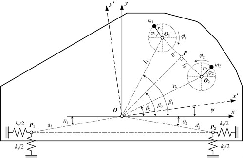
The dynamic vibration system model was established to study the VSSIMBS motion law, as shown in Fig. 2. In the figure, represents the screen body centroid; is the rotation center of eccentric block 1; is the rotation center of eccentric block 2; is the midpoint of ; and and are the spring supporting points. During the VSSIMBS operation, the screen body moves in the and directions, and rotates around the centroid . Thus, the is the fixed coordinate system, while is the dynamic coordinate system. According to the Lagrange equation, the vibration system’s kinetic and potential energy expressions can be obtained.
Fig. 2Dynamic model of VSSIMBS
The kinetic energy of the vibration system () is:
where is the screen body mass (excluding the eccentric blocks); is the block 1 mass; is the block 2 mass; is the block 1 eccentric distance; is the block 2 eccentric distance; is the horizontal screen body displacement; is the vertical screen body displacement; is the screen body swing angle; is the rotational inertia of the screen body; and are rotational inertias of eccentric blocks 1 and 2, respectively; is the () distance; is the distance; is the distance; is the angle between the length and -axis; is the angle between the length and -axis; is the angle between the length and -axis; is the block 1 rotation angle; and is the block 2 rotation angle.
The potential energy of the vibration system () is:
where is the spring stiffness coefficient in the horizontal direction; is the spring stiffness coefficient in the vertical direction; is the distance; is the angle between the length and -axis; and is the angle between the length and -axis.
The energy dissipation function of the vibration system () is written as follows:
where is the spring damping coefficient in the horizontal direction; is the spring damping coefficient in the vertical direction; and are the exciters 1 and 2 damping coefficients, respectively.
The expressions of kinetic energy, potential energy, and energy dissipation function were then substituted into the following Lagrange equation:
where is the electromagnetic torque of motor 1, and is the electromagnetic torque of motor 2.
According to the Lagrange equation, five differential motion equations can be obtained for the observed vibration system. The relationships are as follows:
The dynamic vibration system model can be established by simplifying the differential motion equations as follows:
where represents the system rotational inertia in the swing direction; is the system stiffness coefficient in the swing direction; and is the system damping coefficient in the swing direction.
3. Force analysis
During the vibrating screen operation, the motor rotates the eccentric block located on its shaft. As it rotates, the eccentric block produces the inertial force; the resultant inertial force generated by the two eccentric blocks moves the vibrating screen. Since the eccentric block is installed on the vibrating screen, the eccentric block moves with the screen body. It should also be noted that the vibrating screen movement affects the eccentric block rotation and the motor’s output characteristics.
The force analysis of two eccentric blocks during the movement process is shown in Fig. 3. If the mass and eccentric distance of blocks are equal (, ), it is necessary to ensure that the resultant inertial forces in the -direction will be equal in magnitude and opposite in direction, achieving the synchronous vibrating screen movement. Thus, the resultant inertial force of both eccentric blocks will be in the vibrating direction, meaning that the vibrating screen will move steadily without swinging.
Fig. 3Force analysis of eccentric blocks
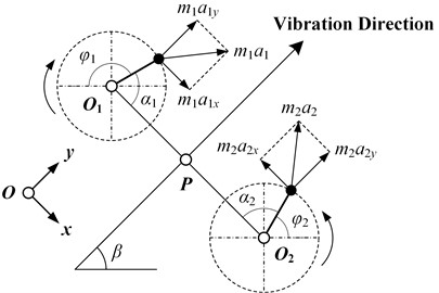
Based on the above-presented analysis, the conditions in which the motors will achieve synchronous movement are:
From Fig. 3, it is possible to conclude that:
Eq. (21) can now be expressed as:
Finally, the phase difference 2 of the two motors is:
where is the vibration direction angle of the vibrating screen.
By continuously adjusting the motor speeds and torques, the eccentric blocks will reach equilibrium, achieving synchronous movement. However, motor parameters, masses, and eccentric distances for each of the two eccentric blocks cannot be completely equal. Therefore, in the actual operation process, the vibrating screen will inevitably reach the transition process between non-synchronization and synchronization. This period will last until the motor speeds, torques, and phase differences are constant. Studying the variation law of several parameters is essential to investigate the vibrating screen’s motion process, such as speed, torque, and phase difference. Once the vibrating screen runs steadily, motors have equal speeds and constant phase differences, and synchronous movement is achieved.
4. Electromechanical coupling simulation
4.1. Simulation model
The motors used in the VSSIMBS are squirrel-cage three-phase asynchronous motors. The vibration system mechanical load was used as input, while the speed, electromagnetic torque, and motor phase were the outputs. The motor was powered by a three-phase power supply with an adjustable frequency. The power supply and the motor were connected via a three-phase circuit breaker for time switching. The drive system simulation model is shown in Fig. 4.
Fig. 4Simulation model of the drive system
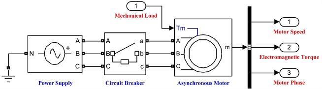
The asynchronous motor output speed, i.e., angular velocity, was obtained for the given three-phase power supply, making it possible to calculate the angular acceleration. By substituting the angular velocity and angular acceleration into Eqs. (9), (10), and (11), the displacement in the -direction, the displacement in the -direction, and the vibrating screen swing angle were obtained, respectively. Furthermore, by substituting the same parameters into Eqs. (12) and (13), the motor’s mechanical load in the operation process was found; the load was then fed back to the motor to adjust its output parameters. Thus, the coupling relationship between the motors and the vibrating screen was established.
The electromechanical coupling simulation model of the VSSIMBS was established in Simulink based on the dynamic model, as shown in Fig. 5. In the figure, the differential motion equation in the -direction was written according to Eq. (9). In contrast, the differential motion equation in the -direction was established according to Eq. (10). Similarly, the differential motion equation in direction and load equations of motors 1 and 2 were established according to Eqs. (11), (12), and (13), respectively. The simulation parameters used in the model are given in Table 1.
Fig. 5Electromechanical coupling simulation model of VSSIMBS
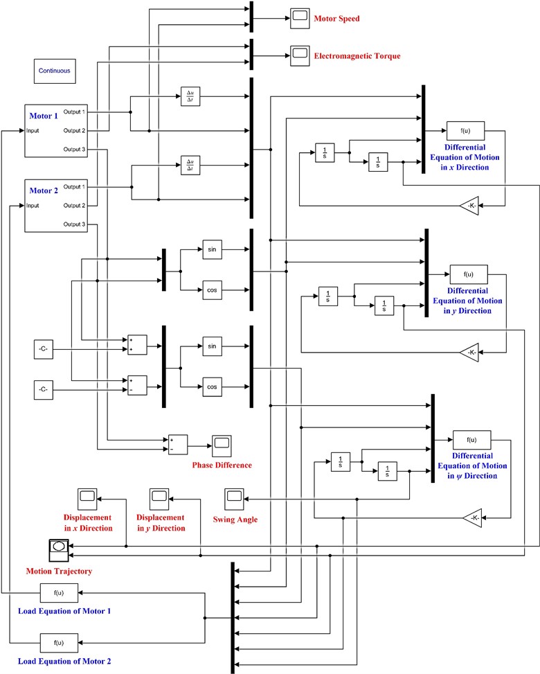
Table 1Simulation parameters of electromechanical coupling model
Parameter | Value | Parameter | Value |
(kg) | 1519.28 | (m) | 0.19 |
(kg) | 60.89 | (m) | 0.36 |
(kg) | 60.89 | (m) | 0.33 |
(kg·m2) | 1823.22 | (N/m) | 200000 |
(kg·m2) | 0.57 | (N/m) | 600000 |
(kg·m2) | 0.57 | (N·m/rad) | 245100 |
(kg·m2) | 1900.55 | (N·s/m) | 2000 |
(kg·m2) | 0.79 | (N·s/m) | 6000 |
(kg·m2) | 0.79 | (N·m·s/rad) | 2451 |
(m) | 0.65 | (N·m·s/rad) | 0.008 |
(m) | 0.77 | (N·m·s/rad) | 0.008 |
(rad) | 0.61 | (rad) | 0.84 |
(rad) | 0.51 | (rad) | 1.31 |
(m) | 0.06 | (rad) | 0.28 |
(m) | 0.06 |
4.2. Frequency control simulation experiment
The asynchronous motor output speed can be expressed as:
where is the power supply frequency; is the number of pole pairs; and is the slip ratio.
In this experiment, the three-phase AC power supply (Simulink) was used to change the motor power supply frequency to enable the variable frequency speed regulation. The rated motor power was 3 kW, the number of pole pairs was 3, the slip ratio was 0, and the rated motor speed was calculated as 1000 r/min (given the power supply frequency of 50 Hz).
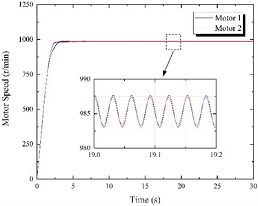
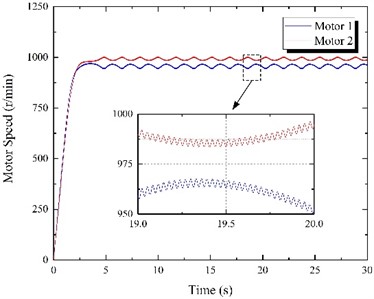
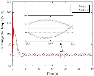
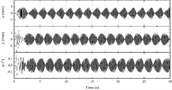
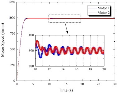
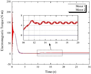
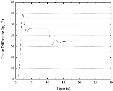
The power supply frequencies for both motors ( and ) were set to 50 Hz, while the simulation time was 30 s. The experiment was conducted, and the results are shown in Fig. 6. It is evident from Fig. 6(a) that the motor speed gradually increases during the starting phase; however, the speeds of the two motors are not equal. After the 3 s transition process, the speeds of both motors become constant, and their motion curves practically overlap. The speed stabilized at 994.32 r/min, and the motors achieved synchronous movement. Furthermore, as shown in Fig. 6(b), motor electromagnetic torques are relatively high during the start-up stage, but they gradually decrease until finally stabilizing at approximately 2.88 N·m. It can be seen from Fig. 6(c) that the initial phase difference between the motors is 0. After the continuous adjustment of the eccentric blocks in the vibration process, the final phase difference was stable at 91.68°. In other words, the motor 1 phase was 91.68° ahead of motor 2. At that moment, the resultant force direction of the two eccentric blocks is identical to the vibrating screen motion direction. Moreover, the vibrating screen motion will stabilize once the phase difference stabilizes (Fig. 6(e)). The horizontal direction amplitude is 3.17 mm, the vertical direction amplitude is 3.15 mm, the swing angle is 0.0072°, and the vibration direction angle is 44.82°. The swing angle is relatively small and can be ignored, while the vibrating screen motion trajectory in the stable stage is practically a straight line, as shown in Fig. 6(d).
The motor 1 power supply frequency changed to 49 Hz, and its theoretical output speed was reduced to 980 r/min. On the other hand, the motor 2 power supply frequency remained constant at 50 Hz. The simulation time was 30 s, and the results are shown in Fig. 7.
Fig. 6Results of frequency control experiment when f1= 50 Hz and f2= 50 Hz
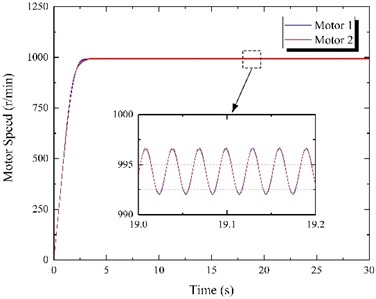
a) Motor speed
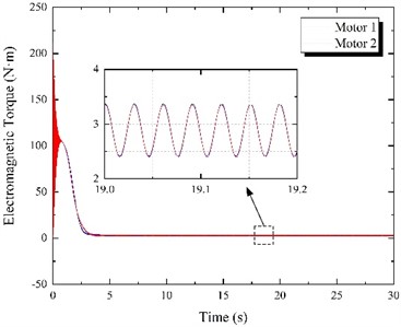
b) Electromagnetic torque
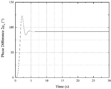
c) Phase difference
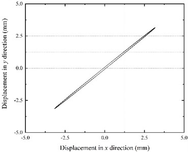
d) Motion trajectory
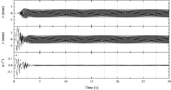
e) Horizontal displacement, vertical displacement, and swing angle
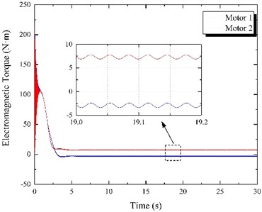
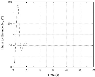
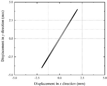
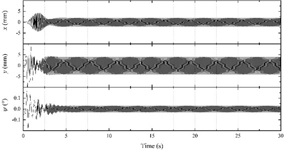
Although the motor power supply frequencies are different, after the interaction during the start-up stage, motors achieve the same speed and synchronous movement (Fig. 7(a)). The speed slightly fluctuates at 985.35 r/min, which is above the theoretical speed of motor 1 (980 r/min) and below the synchronous speed under the same frequency (994.32 r/min). Moreover, the electromagnetic torques of both motors in the stable stage are rather different (Fig. 7(b)). The motor 1 electromagnetic torque is stable at -2.89 N·m, while motor 2 stabilizes at about 7.36 N·m, which is higher than the synchronous torque for the same frequency (2.88 N·m). Such behavior shows that in the stable vibrating screen operation stage, the motor 1 electromagnetic torque is an obstacle to the vibration system operation. Thus, motor 2 has to output higher electromagnetic torque to drive both eccentric blocks and achieve synchronous movement. As shown in Fig. 7(c), the balance positions of two eccentric blocks change, and the phase difference between the motors becomes 53.29°. Moreover, according to Fig. 7(e), the vibrating screen steady-state response changes since the motor 2 electromagnetic torque is higher than that of motor 1. The amplitude in the horizontal direction decreases to 1.98 mm, while the amplitude in the vertical direction increases to 4.04 mm. The swing angle increases to 0.03°, and the vibration direction angle increases to 63.89°. The vibrating screen motion trajectory in the steady state is shown in Fig. 7(d).
Fig. 7Results of frequency control experiment when f1= 49 Hz and f2= 50 Hz
a) Motor speed
b) Electromagnetic torque
c) Phase difference
d) Motion trajectory
e) Horizontal displacement, vertical displacement, and swing angle
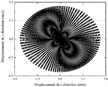
The motor 1 power supply frequency waschanged to 48 Hz, and the theoretical output speed of motor 1 dropped to 960 r/min. On the other hand, the motor 2 power supply frequency remained unchanged at 50 Hz. The simulation time was 30 s, and the results are shown in Fig. 8. According to Fig. 8(a), two motors cannot reach the synchronous speed during the operation. The motor 2 speed is higher than motor 1 speed, and the fluctuation amplitude is relatively large. The electromagnetic torques of motors are not constant (Fig. 8(b)), and the fluctuations are large, causing constant changes in block rotation speeds. Since motor 2 speed is greater than motor 1 speed (Fig. 8(c)), the phase difference increases in the negative direction (motor 2 leads motor 1). Thus, the resultant force direction of two eccentric blocks changes continuously. Finally, it can be seen from Fig. 8(e) that motor movements cannot be synchronized; thus, the vibrating screen cannot reach stability – the amplitude constantly changes, along with the vibration direction angle. The vibrating screen motion trajectory is shown in Fig. 8(d).
Fig. 8Results of frequency control experiment when f1= 48 Hz and f2= 50 Hz
a) Motor speed
b) Electromagnetic torque
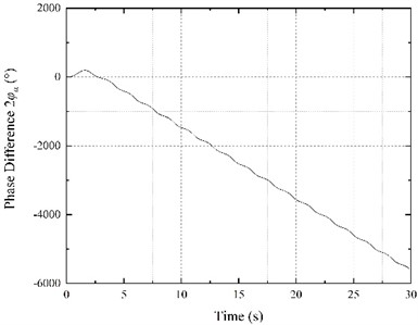
c) Phase difference
d) Motion trajectory
e) Horizontal displacement, vertical displacement, and swing angle
4.3. Vibration synchronization simulation experiment
The vibration synchronization process is carried out as follows: when motor movements synchronize, the power supply of one motor is cut off. Next, two eccentric blocks will transition from the original to the new synchronous state. In this experiment, a three-phase Simulink circuit breaker was used to power off the motor regularly. The initial power supply frequencies were set to 50 Hz for both motors, and the motor 1 power supply was cut off after 10 s. The simulation time was 30 s, and the results are shown in Fig. 9.
Fig. 9Results of vibration synchronization experiment
a) Motor speed
b) Electromagnetic torque
c) Phase difference
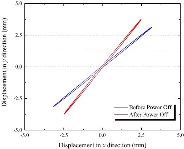
d) Motion trajectory
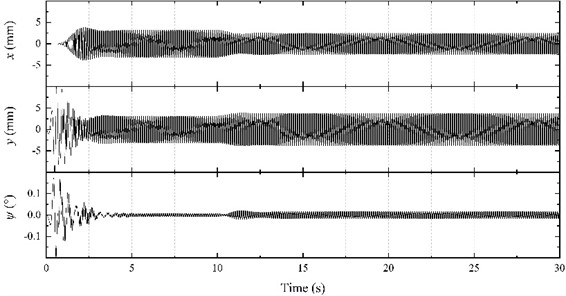
e) Horizontal displacement, vertical displacement, and swing angle
According to Fig. 9(a), in the first 10 s, the speed of the two motors is similar to the previously explored case where both frequencies were 50 Hz, reaching the synchronous speed of 994.32 r/min. At 10 s, the power of motor 1 is cut off, and the speed of the two motors decreases rapidly. After the adjustment period, the two motors gradually reach synchronous movement, and the speed finally stabilizes at about 989.97 r/min. According to Fig. 9(b), when motor 1 is powered off at 10 s, the electromagnetic torque of motor 1 instantaneously drops to 0, while the electromagnetic torque of motor 2 gradually increases from 2.89 to 5.04 N·m to overcome the load torque of motor 1 and reach a new equilibrium position. It can be seen from Fig. 9(c) that with the change of synchronous movement state, the phase difference of the two motors gradually decreases from 91.66° to 68.15°. According to Fig. 9(e), the steady-state response of the vibrating screen also changes before and after the power outage. The amplitude in the horizontal direction decreases from 3.15 mm to 2.50 mm, the amplitude in the vertical direction increases from 3.12 mm to 3.74 mm, the swing angle increases from 0.0072° to 0.016°, and the vibration direction angle increases from 44.73° to 56.24°. The vibrating screen trajectory before and after the power outage is shown in Fig. 9(d).
5. Conclusions
In this work, the motion differential equations of VSSIMBS were derived based on the Lagrange equation, and the dynamic vibration system model was established. The force condition of eccentric blocks in the operation process was analyzed, obtaining the stable vibration system operation condition. The electromechanical coupling simulation model of the vibrating screen was established in Simulink using the differential motion equations, and the vibrating screen operation process was simulated numerically. The influences of the driving motor output characteristics on the vibration system operation stability were studied by carrying out the frequency control and vibration synchronization experiments. Based on the results, the following conclusions were made:
1) The frequency control experiment results have shown that when the output characteristics of two motors are either the same or similar, synchronous movement can be achieved by adjusting the phase difference. The steady-state response of the vibration system can be obtained, and the vibrating screen can operate stably. When the output characteristics of the two motors are very different, synchronous movement cannot be achieved. Thus, the stable vibration system response value cannot be obtained, and the vibrating screen cannot operate steadily.
2) The vibration synchronization experiment results have shown that when the motors are in the synchronous motion state, and the power supply of one motor is cut off, they continue to operate synchronously. Before powering off, both motors contribute energy to the vibration system. After the power-off, only one motor provides the energy. Consequently, the phase difference between the two changes, and the two eccentric blocks reach a new equilibrium position. The motors also transition from the original synchronous state to a new synchronous state. Therefore, the vibration system energy is redistributed by adjusting the phase difference to ensure stable vibrating screen operation.
3) This study indicates the influence of the motor’s output characteristics on the motion state of the vibrating screen. The operating trajectory of the vibrating screen can be changed by adjusting the speed of the excitation motors to stabilize the vibrating screen operation. Thus, a reference for designing and developing a novel vibrating screen is provided.
References
-
H. Jiang et al., “Kinematics characteristics of the vibrating screen with rigid-flexible screen rod and the behavior of moist coal particles during the dry deep screening process,” Powder Technology, Vol. 319, pp. 92–101, Sep. 2017, https://doi.org/10.1016/j.powtec.2017.06.036
-
Z. Wang, X. Wang, J. Zhuang, Z. Kou, and C. Liu, “Multiple parameter collaborative optimization of a particle separation equipment for coal cleaning production,” Journal of Environmental Chemical Engineering, Vol. 9, No. 4, p. 105646, Aug. 2021, https://doi.org/10.1016/j.jece.2021.105646
-
H. Jiang et al., “Effect of excitation parameters on motion characteristics and classification performance of rigid-flexible coupled elastic screen surface for moist coal,” Advanced Powder Technology, Vol. 31, No. 3, pp. 1196–1208, Mar. 2020, https://doi.org/10.1016/j.apt.2019.12.029
-
M. Pan et al., “Kinematics of a novel screen surface and parameter optimization for steam coal classification,” Powder Technology, Vol. 364, pp. 382–391, Mar. 2020, https://doi.org/10.1016/j.powtec.2020.02.007
-
L. Peng et al., “A review on the advanced design techniques and methods of vibrating screen for coal preparation,” Powder Technology, Vol. 347, pp. 136–147, Apr. 2019, https://doi.org/10.1016/j.powtec.2019.02.047
-
Z. Wang, C. Liu, J. Wu, H. Jiang, and Y. Zhao, “Impact of screening coals on screen surface and multi-index optimization for coal cleaning production,” Journal of Cleaner Production, Vol. 187, pp. 562–575, Jun. 2018, https://doi.org/10.1016/j.jclepro.2018.03.238
-
B. Wen, “Recent development of vibration utilization engineering,” Frontiers of Mechanical Engineering in China, Vol. 3, No. 1, pp. 1–9, Mar. 2008, https://doi.org/10.1007/s11465-008-0017-2
-
X. Zhang, D. Gu, H. Yue, M. Li, and B. Wen, “Synchronization and stability of a far-resonant vibrating system with three rollers driven by two vibrators,” Applied Mathematical Modelling, Vol. 91, pp. 261–279, Mar. 2021, https://doi.org/10.1016/j.apm.2020.07.047
-
C. Zhao, H. Zhu, Y. Zhang, and B. Wen, “Synchronization of two coupled exciters in a vibrating system of spatial motion,” Acta Mechanica Sinica, Vol. 26, No. 3, pp. 477–493, Jun. 2010, https://doi.org/10.1007/s10409-009-0311-1
-
C. Huygens, Horologium Oscillatorium. Paris: F. Muguet, 1672.
-
I. Blekhman, Vibrational Mechanics. Singapore: World Scientific, 2000.
-
I. Blekhman, Synchronization in Science and Technology. New York: ASME Press, 1988.
-
J. M. Balthazar, J. L. P. Felix, and R. M. L. R. F. Brasil, “Short Comments on Self-Synchronization of Two Non-Ideal Sources Supported by a Flexible Portal Frame Structure,” Journal of Vibration and Control, Vol. 10, No. 12, pp. 1739–1748, Dec. 2004, https://doi.org/10.1177/1077546304041754
-
J. M. Balthazar, J. L. P. Felix, and R. M. Brasil, “Some comments on the numerical simulation of self-synchronization of four non-ideal exciters,” Applied Mathematics and Computation, Vol. 164, No. 2, pp. 615–625, May 2005, https://doi.org/10.1016/j.amc.2004.06.010
-
H. Nijmeijer, “A dynamical control view on synchronization,” Physica D: Nonlinear Phenomena, Vol. 154, No. 3-4, pp. 219–228, Jun. 2001, https://doi.org/10.1016/s0167-2789(01)00251-2
-
A. L. Fradkov, B. Andrievsky, and R. J. Evans, “Adaptive observer-based synchronization of chaotic systems with first-order coder in the presence of information constraints,” IEEE Transactions on Circuits and Systems I: Regular Papers, Vol. 55, No. 6, pp. 1685–1694, Jul. 2008, https://doi.org/10.1109/tcsi.2008.916410
-
A. L. Fradkov, B. Andrievsky, and R. J. Evans, “Synchronization of nonlinear systems under information constraints,” Chaos: An Interdisciplinary Journal of Nonlinear Science, Vol. 18, No. 3, p. 037109, Sep. 2008, https://doi.org/10.1063/1.2977459
-
P. Perlikowski, A. Stefański, and T. Kapitaniak, “1:1 Mode locking and generalized synchronization in mechanical oscillators,” Journal of Sound and Vibration, Vol. 318, No. 1-2, pp. 329–340, Nov. 2008, https://doi.org/10.1016/j.jsv.2008.04.021
-
K. Czołczynski, P. Perlikowski, A. Stefański, and T. Kapitaniak, “Synchronization of self-excited oscillators suspended on elastic structure,” Chaos, Solitons and Fractals, Vol. 32, No. 3, pp. 937–943, May 2007, https://doi.org/10.1016/j.chaos.2006.07.022
-
R. Yamapi and P. Woafo, “Dynamics and synchronization of coupled self-sustained electromechanical devices,” Journal of Sound and Vibration, Vol. 285, No. 4-5, pp. 1151–1170, Aug. 2005, https://doi.org/10.1016/j.jsv.2004.09.011
-
R. Yamapi, F. M. Moukam Kakmeni, and J. B. Chabi Orou, “Nonlinear dynamics and synchronization of coupled electromechanical systems with multiple functions,” Communications in Nonlinear Science and Numerical Simulation, Vol. 12, No. 4, pp. 543–567, Jul. 2007, https://doi.org/10.1016/j.cnsns.2005.05.003
-
B. Wen, H. Zhang, S. Liu, Q. He, and C. Zhao, Theory and Techniques of Vibrating Machinery and Their Applications. Beijing: Science Press, 2010.
-
B. Wen, J. Fan, C. Zhao, and W. Xiong, Vibratory Synchronization and Controlled Synchronization in Engineering. Beijing: Science Press, 2009.
-
C. Zhao, H. Zhu, R. Wang, and B. Wen, “Synchronization of two non-identical coupled exciters in a non-resonant vibrating system of linear motion. Part I: theoretical analysis,” Shock and Vibration, Vol. 16, No. 5, pp. 505–515, 2009, https://doi.org/10.3233/sav-2009-0484
-
C. Zhao, H. Zhu, T. Bai, and B. Wen, “Synchronization of two non-identical coupled exciters in a non-resonant vibrating system of linear motion. Part II: numeric analysis,” Shock and Vibration, Vol. 16, No. 5, pp. 517–528, 2009, https://doi.org/10.3233/sav-2009-0485
-
X. Zhang, B. Wen, and C. Zhao, “Experimental investigation on synchronization of three co-rotating non-identical coupled exciters driven by three motors,” Journal of Sound and Vibration, Vol. 333, No. 13, pp. 2898–2908, Jun. 2014, https://doi.org/10.1016/j.jsv.2014.01.022
-
X. Zhang, B. Wen, and C. Zhao, “Vibratory synchronization transmission of a cylindrical roller in a vibrating mechanical system excited by two exciters,” Mechanical Systems and Signal Processing, Vol. 96, pp. 88–103, Nov. 2017, https://doi.org/10.1016/j.ymssp.2017.04.007
-
H. Peng, Y. Hou, P. Fang, M. Zou, and Z. Zhang, “Synchronization analysis of the anti-resonance system with three exciters,” Applied Mathematical Modelling, Vol. 97, pp. 96–112, Sep. 2021, https://doi.org/10.1016/j.apm.2021.03.055
-
H. Peng, Y. Hou, P. Fang, M. Zou, and Z. Zhang, “Theoretical and experimental investigation on synchronization of secondary vibration isolation system with two exciters,” Journal of Sound and Vibration, Vol. 511, p. 116351, Oct. 2021, https://doi.org/10.1016/j.jsv.2021.116351
-
M. Zou, P. Fang, Y. Hou, Y. Wang, D. Hou, and H. Peng, “Synchronization analysis of two eccentric rotors with double-frequency excitation considering sliding mode control,” Communications in Nonlinear Science and Numerical Simulation, Vol. 92, p. 105458, Jan. 2021, https://doi.org/10.1016/j.cnsns.2020.105458
-
M. Zou, P. Fang, Y. Hou, and H. Peng, “Investigation on multiple-frequency synchronization experiment of vibration system with dual-rotor actuation,” Mechanical Systems and Signal Processing, Vol. 164, p. 108261, Feb. 2022, https://doi.org/10.1016/j.ymssp.2021.108261
-
Z. Wang, C. Liu, J. Wu, H. Jiang, B. Song, and Y. Zhao, “A novel high-strength large vibrating screen with duplex statically indeterminate mesh beam structure,” Journal of Vibroengineering, Vol. 19, No. 8, pp. 5719–5734, Dec. 2017, https://doi.org/10.21595/jve.2017.18319
-
Y. Zhao, C. Liu, X. He, C. Zhang, Y. Wang, and Z. Ren, “Dynamic design theory and application of large vibrating screen,” Procedia Earth and Planetary Science, Vol. 1, No. 1, pp. 776–784, Sep. 2009, https://doi.org/10.1016/j.proeps.2009.09.123
-
Y. Zhao, J. Liu, X. Wei, Z. Luo, Q. Chen, and S. Song, “New progress in the processing and efficient utilization of coal,” Mining Science and Technology (China), Vol. 21, No. 4, pp. 547–552, Jul. 2011, https://doi.org/10.1016/j.mstc.2011.06.015
Cited by
About this article

The research work is financially supported by the Natural Science Foundation of Shandong Province (Grant No. ZR2019PEE024), and the Open Foundation of State Key Laboratory of Mineral Processing (Grant No. BGRIMM-KJSKL-2022-11).
The datasets generated during and/or analyzed during the current study are available from the corresponding author on reasonable request.
Zhenqian Wang: data curation, methodology, writing – original draft preparation, writing – review and editing. Jida Wu: investigation. Zhaojun Kou: software. Yuanming Zhang: resources. Chusheng Liu: conceptualization.
The authors declare that they have no conflict of interest.
