Abstract
Automatic transmission system is the core part of vehicle transmission processing, which can improve driving safety. In order to improve the shift effect of automotive automatic mechanical transmission and narrow the gap between the vehicle speed and the expected speed, an automotive automatic mechanical transmission system based on torsional damping was designed in the experiment. On the basis of hardware composed of different modules and fuzzy control algorithm, the system realizes the software design of vehicle automatic mechanical transmission system. The experimental results show that when the system is applied in practice, the gear selection time of the vehicle is between 0.2 s-0.3 s, and the gear shift time is between 0.3 s-0.4 s. The gap between the vehicle speed and the expected speed, and between the vehicle speed and the expected speed is small. The practical application effect is good.
Highlights
- The hardware part is designed in detail, which lays the foundation for software operation.
- The torsional damping model is constructed, and the driving equation is obtained.
- Fuzzy control algorithm is incorporated for control process of establishing mathematical model.
1. Introduction
The development of national economy promotes the development of automobile industry. With the progress of science and technology, communication, control and network are more and more widely used in automobile industry. Automotive electronic control technology can effectively improve the economy, safety and comfort of automotive fuel, and promote the further development of automotive industry [1]. At present, the development direction of automobile electronic control technology is automobile mechanical automatic transmission system, which can improve the safety and comfort of automobile driving. The domestic automobile manufacturing industry is in the stage of rapid development. Although the domestic automobile has greatly improved from modeling to vehicle performance in recent years, there is still a certain gap in the design and control of its transmission system with some developed countries [2]. Manual transmission is still the mainstream product of tractor transmission because of its low cost, high efficiency and mature production technology. However, when manual transmission shifts, the power is interrupted, it is difficult to shift, and the driving performance of the vehicle depends on the driving level. At the same time, complex shift operations are easy to cause driver fatigue and affect road safety [3]. Therefore, automatic transmission technology has become an important research direction, and the rapid development of electronic technology and its wide application in vehicles also provide a good opportunity for the development of automatic transmission [4]. Automotive mechanical automatic transmission system has become the first choice of automotive transmission system because of its simple structure, good inheritance and low development cost. Therefore, it is of great significance to design a new automotive mechanical automatic transmission system.
Aiming at the important research topic of auto mechanical automatic transmission system, Zhang et al. [5] proposed a kind of auto electronically controlled automatic transmission system based on MCU. The overall structure of the system includes sensor module, speed automatic control module, single-chip integrated information processing module, reset module, impedance matching module and output control module, etc., with single-chip as the core control chip for the reciprocating control of the automobile electronically controlled automatic transmission system. VIX bus processing technology is used for signal processing of auto electronic control automatic variable speed, the upper computer control module of auto mechanical automatic variable speed system is constructed, and remote automatic control and background embedded design are carried out. C51 single chip microcomputer is used as the computer processing center unit, and DSP is used to process auto electronic control automatic variable speed signal. In the embedded microprocessor environment, the hardware modularization development of automotive electronic control automatic transmission system is completed. Zeng [6] proposed a mechanical automatic transmission shift intelligent vehicle mechanical automatic transmission system. In the torque phase, in order to prevent power interruption in the process of shifting, the coupling element intelligently controls the shift up and down. In inertial phase, after get the quadratic performance index to solving Riccati matrix differential equation for phase torque clutch friction torque change rate of the optimal trajectory, using conversion relation between clutch pressure and moment, obtain optimal control trajectory phase torque clutch pressure, in order to realize intelligent control of automatic mechanical transmission shift. In the design of the automatic mechanical transmission system of the automobile, for the improvement of the shift effect of the automatic transmission and the reduction of the gap between the automobile speed and the expected speed, the reduction of torsional vibration is a technical improvement needed to achieve these goals. In the existing research, some scholars have established a dynamic model of the two speed transmission gear transmission system including side clearance and bearing clearance based on the gear vibration characteristics of the electric vehicle transmission system. The results show that changing the gear backlash and the support bearing clearance within a certain range will affect the vibration characteristics of the electric vehicle gear transmission system. The gear backlash will affect the amplitude of the radial vibration displacement and acceleration of the bearing. When the gear transmission error increases, the radial vibration displacement of the bearing decreases, indicating that there is a coupling relationship between the backlash and the bearing clearance [7]. The influence of torque fluctuation amplitude and transmission clearance of permanent magnet synchronous motor (PMSM) on the torsional vibration stability of wheel side direct drive transmission system (WDTS) was analyzed experimentally. The results show that the nonlinear characteristics of WDTS torsional vibration response are relatively complex, which affects the stable operation of WDTS under the effect of system transmission clearance [8]. Manchi V. et al. proposed a centrifugal double pendulum vibration absorber (CDPVA), which simplifies the design of high-order vibration absorber by using the series connection of two pendulums. In the experiment, the analysis results were compared with the simulation results and the vehicle test was carried out. The results showed that the torsional vibration of the drive shaft of the rear wheel drive vehicle and the vibration level of the seat position were reduced through the improvement of the method [9]. According to the structural characteristics of harmonic gear reducer, and considering the nonlinear torsional stiffness and other factors, the nonlinear torsional dynamic model of harmonic gear reducer is established in the experiment. The results show that the speed, transmission error and motor inertia are in direct proportion to the amplitude of the harmonic gear reducer, while the load inertia and damping are negatively related to the amplitude [10].
Based on the above research, it can be seen that the design of automatic transmission and the establishment of the system are affected by many aspects, and researchers have continuously improved these methods. However, there are still some problems in the research and practical application of these systems and automatic transmissions, such as long gear selection and shifting time, small gap between vehicle speed and expected speed, and large gap between vehicle speed and expected speed. In order to solve the problems in traditional systems, this paper improves the hardware and software of the automatic transmission system, and innovatively fuses the fuzzy control algorithm to improve the method performance. On this basis, a vehicle automatic mechanical transmission system based on torsional vibration reduction is designed, and the effectiveness of the system is tested through experiments.
2. Design of automobile mechanical automatic transmission system
2.1. Hardware of automotive mechanical automatic transmission system
2.1.1. Power circuit module
The MC9S12XS128 master control chip selected in this paper is a 16-bit high-performance automotive chip launched by Freescale Company. MC9S12XS128 has 128K bytes of Flash and 8K bytes of RAM internal memory. The timer module is composed of 1 16-bit independent running counter and 8 16-bit input capture and output comparison channels. The analog-to-digital conversion module can realize 16-channel 8-bit/10-bit/12-bit analog conversion channel. It has two serial communication interfaces and corresponding peripheral circuit interfaces; Provides the CAN interface. The normal work of microcontroller is inseparable from the peripheral circuit, such as power supply circuit, clock circuit, reset circuit, program read and write circuit and anti-interference circuit. Power supply circuit and power supply circuit for the smooth operation of the system is of great significance, so focus on the design of power supply circuit, anti-interference circuit.
(1) Power supply circuit.
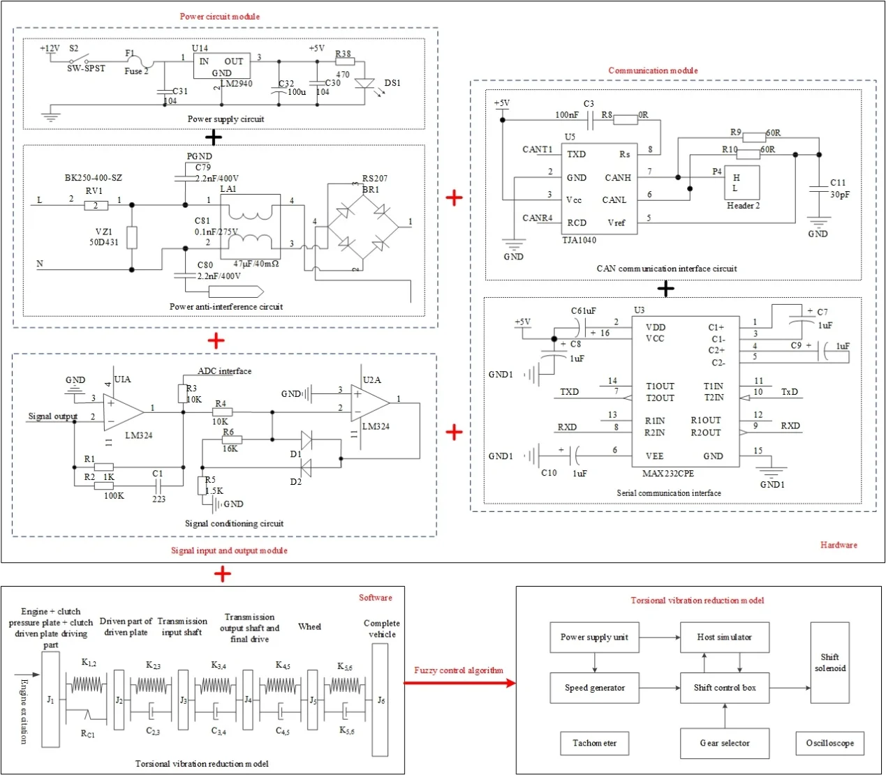
In order to meet the needs of single-chip microcomputer for 5 V stabilized power supply, it is necessary to design a 12 V to 5 V circuit. Using voltage regulator chip LM2940 to provide voltage, the chip is low voltage differential linear voltage regulator chip, compared with 7805 regulator chip has a greater advantage, the minimum differential pressure is less than 0.8 V. C32 can store large power, can provide emergency power for the system when power failure. In order to suppress high-frequency noise, the input and output terminals of the chip are connected with decoupling capacitors. The power supply circuit is shown in Fig. 1.
Fig. 1Power supply circuit
(2) Anti-interference circuit.
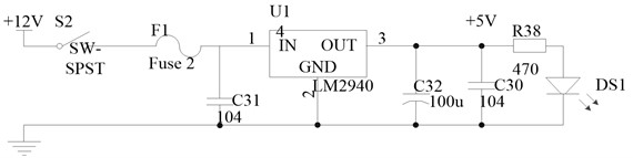
It is very important to design the anti-interference of the auto mechanical automatic transmission system. The research shows that most of the interference enters the system through the coupling of the power supply, so the reliability of the power supply largely determines whether the auto mechanical automatic transmission system can run stably. The generator output is connected to the system power supply step-down circuit through the power supply anti-interference circuit [11, 12]. The power anti-interference circuit is shown in Fig. 2.
Fig. 2Power anti-interference circuit
In Fig. 2, RV1 is a thermistor, VZ1 is a varistor, and LA1 is a common-mode choke. The circuit can effectively suppress the surge and group pulse interference.
2.1.2. Signal input and output module
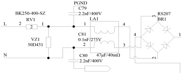
0 sensor provides signal source, and then through the control switch and adjustment circuit input to the master control system. Analog signals need to be adjusted before A/D conversion. Analog signals are easy to be mixed with many interference signals in the process of transmission, so direct sampling will certainly cause deviation to the results. Therefore, a filter circuit is needed to carry out simple filtering of analog signals. The input analog signal of analog-to-digital conversion module in TMS320F2812 peripherals cannot be any analog signal, and the input range of analog voltage is 0-3 V. In the actual signal acquisition, it is not guaranteed that the signal obtained is in the range of all analog voltage input, so the signal input outside the range may damage the analog signal input port [13]. Therefore, it must be processed before sampling can be carried out through A/D module. At the same time, the sampled analog signal has a voltage range and is a unipolar signal, so a signal conditioning circuit is needed to limit the analog input voltage to 0-3 V. The signal conditioning circuit is shown in Fig. 3.
Fig. 3Signal conditioning circuit
2.1.3. Communication module
(1) Serial communication.
Serial communication is mainly used in the debugging phase of auto mechanical automatic variable speed system. Through RS232 serial communication protocol, the communication between the host and the debugged equipment is realized to check whether the operation of the equipment is reasonable [14]. TTL logic level of microcontroller is different from RS232 logic level of upper computer. Before realizing communication, level conversion chip should be used to convert level type to realize serial communication between upper computer and microcontroller. The serial communication interface is shown in Fig. 4.
(2) CAN communication interface circuit.
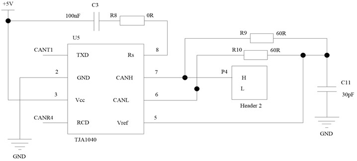
CAN communication interface circuit is a CAN transceiver circuit based on TJA1040 chip. The transceiver connects the corresponding CAN node to the CAN bus and CAN provide the CAN communication high current. This connection mode CAN protect the CAN node from the damage of the bus high current. CAN communication CAN enhance the communication integration of complex systems, and has strong anti-interference performance and high reliability [15]. The microprocessor MC9S12XS128 used in this paper has two independent CAN modules and conforms to the commonly used CAN2.0A/B protocol. CAN communication interface circuit is shown in Fig. 5.
Fig. 4Serial communication interface
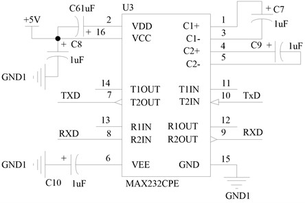
Fig. 5CAN communication interface circuit
2.2. Automotive mechanical automatic transmission system software
2.2.1. Torsional vibration reduction model construction
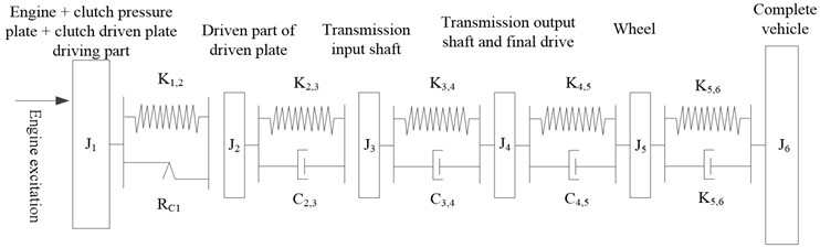
The form of torsional vibration is very complex. Any component is not an absolute rigid body or elastomer, but a rotating body with both stiffness and inertia, so the absolute mechanical model cannot be established. In order to make theoretical analysis possible, the actual system is generally simplified into an ideal system that can be mathematically calculated, that is, the actual system is assumed to be composed of concentrated inertia with only rotational inertia but no elasticity and some connecting parts with only elastic deformation but no inertia. This idealized model is called equivalent system. Of course, such an equivalent system is equivalent to the actual system in terms of torsional vibration characteristics. Practice has proved that as long as the assumption is appropriate and reasonable, the equivalent system is calculated, and the results are basically consistent with the measured values. The torsion model is shown in Fig. 6.
The parameters in the torsional vibration reduction model are explained as follows: is the inertia of the driving part of the engine, clutch pressure plate and clutch driven plate; is the inertia of the driven part of the driven plate; is the moment of inertia of the transmission input shaft; is the rotational inertia of gearbox output shaft and main reducer; is the moment of inertia of the wheel; is the moment of inertia of the whole vehicle; is the torsional stiffness of the driven plate; is the stiffness of the input shaft of the transmission; is the stiffness of transmission output shaft; is the half axle stiffness; is the wheel stiffness; is the damping of driven plate damper; is the damping coefficient of transmission input shaft; is the damping coefficient of transmission output shaft; is the half shaft damping coefficient; is the wheel damping coefficient.
Fig. 6Torsional vibration reduction model
Conduct dynamic analysis on the established dynamic model of the transmission system. According to Newton’s second law [16], the following equations can be established. For the idle speed model, the following equations are established:
For the acceleration model, because the stiffness between the transmission output shaft and the main reducer is very large [17], it can be regarded as a combined inertia unit, and the friction resistance of the whole transmission system is ignored. The following equations can be obtained:
In Eq. (1) and (2), represents the hysteresis of the driven plate damper, represents the exciting torque of the engine, represents the drag torque when the transmission is idling, and represents the resistance torque when the whole vehicle is driving [18].
The theoretical analysis and solution methods of idle model and acceleration model are completely consistent, and the acceleration model is relatively complex. The following part of this paper only describes the analysis of acceleration model, and only gives the analysis results for idle model.
When analyzing the natural characteristics of the system, considering that the influence of damping on the natural characteristics of the system is relatively small, the influence of damping can be ignored; The external excitation and resistance moment do not affect the inherent characteristics of the system and can be ignored. That is, the system model is simplified into an undamped free vibration model, then the above dynamic equations can be simplified into homogeneous equations:
The above equations can be rewritten into matrix form:
where represents the moment of inertia matrix, represents the torsional vibration angle matrix, and represents the stiffness matrix:
Let the solution of the equations be and be the vibration mode of the torsional system, and bring it into the homogeneous equations:
Since , , , let , where represents the natural frequency of the system, let and bring in , then bring this formula into Eq. (5) to obtain the torsional vibration reduction model:
2.2.2. Construction of vehicle driving model
When driving on the road, the car must overcome the rolling resistance and air resistance of the ground. When driving up and down the slope, it must also overcome the component of gravity along the slope, which is called slope resistance . When accelerating, you must also overcome the acceleration resistance . Therefore, the total resistance when the vehicle is running can be calculated as:
(1) Rolling resistance (N).
Rolling resistance refers to the normal and tangential interaction force generated in the contact area between the tire and the road surface when the wheel is rolling [19]. According to the tribological theory, when the vehicle is running without load, the rolling resistance of the vehicle is equal to the gravity of the vehicle multiplied by the rolling resistance coefficient of the tire and then multiplied by the cosine of the slope angle of the road, i.e.:
where represents rolling resistance coefficient, represents road slope angle (°) and represents vehicle gravity (N).
(2) Air resistance (N).
When the car is driving in a straight line, the component of air force in the driving direction is called air resistance. Air resistance is divided into pressure resistance and friction resistance. When the vehicle is running, the air resistance is generally summarized as being directly proportional to the dynamic pressure of the relative speed of the air flow when the vehicle is running, that is:
where represents the air resistance coefficient, which is related to Reynolds number, represents the air density (Kg/m³), represents the windward area (m2), and represents the relative velocity.
When the car moves without wind, the air resistance is:
where represents the driving speed of the vehicle (m/s).
(3) Slope resistance (N).
When the car is driving uphill, the component of the car gravity along the ramp is the slope resistance. Namely:
(4) Acceleration resistance (N).
When the vehicle accelerates, it needs to overcome its mass. The inertial force when accelerating is the acceleration resistance . Then the acceleration resistance has the following expression:
where represents the conversion coefficient of vehicle rotating mass, represents vehicle mass (Kg) and represents driving acceleration (m/s2).
(5) Vehicle driving equation.
According to the mathematical model of vehicle resistance established above, the vehicle driving equation can be obtained as follows:
2.2.3. Design of fuzzy control algorithm for automotive mechanical automatic transmission
Fuzzy control theory has obvious advantages for complex systems with unknown mechanism. It imitates and sublimates human control experience and strategies. It is especially suitable for those controlled processes with nonlinearity and large delay that are difficult to establish accurate mathematical models. In this paper, the fuzzy control theory is used to control the automotive mechanical automatic transmission. The process is as follows:
Let be a set of objects, called universe. Each element in is . If a mapping is given on universe , there is:
Among them, is a subset of and is called the membership function of .
Let and be two fuzzy subsets on the universe, then:
Let be a fuzzy subset, and its membership function determines the degree of relationship between element in and element in , then is called a fuzzy relationship from to . Then the following formula holds:
If is a subset of and is a fuzzy subset of , then the composition of on is a fuzzy relation from to , denoted as , and its membership function is:
In the process of applying fuzzy control technology to mechanical automatic variable speed control, firstly, the throttle opening and speed are fuzzy processed. Here, the fuzzy subset of vehicle speed is selected as slow (), slow (), medium (), high () and high (), and the fuzzy subset of vehicle reverse speed is consistent with the forward direction. The fuzzy subset of throttle opening is also selected as five: small (), small (), medium (), large () and large (). Gear is represented by a single point and can be 1, 2, 3, 4, or 5 grades.
The membership function of each fuzzy subset of the speed is as follows:
The size of parameter directly affects the shape of the membership function curve. If the value of parameter is small, the shape of the membership function curve will be sharp and the resolution will be high. On the contrary, the curve is relatively low and the resolution is low. Since the driver’s sensitivity to the speed is similar, the shapes of all fuzzy subsets can be the same, so let:
In addition, since each fuzzy subset overlaps and influences each other, let be the maximum membership function of the intersection of two fuzzy subsets. When is small, the control sensitivity is high, while when is large, the control stability is good. The driver throttle fuzzy control model established in this paper is based on the following assumptions that the driver tries to keep the actual speed consistent with the expected speed. The driver judges the difference between the actual speed and the expected speed and the actual acceleration of the vehicle, controls the appropriate change of the accelerator pedal, and makes the speed achieve the expected speed. The driver’s fuzzy throttle control rule can be written in the following form:
where , , is a fuzzy subset in the theoretical domain of speed difference, acceleration and throttle opening rate of change, is the actual acceleration of the vehicle, and is the change of the accelerator pedal. Combined with fuzzy control rules, auto mechanical automatic variable speed control is realized, and the algorithm flow is shown in Fig. 7.
Fig. 7Algorithm flow of auto mechanical automatic variable speed control
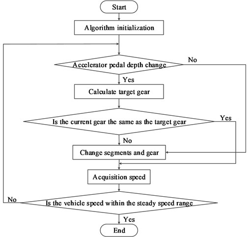
The algorithm flow of automobile mechanical automatic transmission control is: In response to the driver’s operation intention, when the accelerator pedal depth changes, control the hydraulic continuously variable transmission and engine to make the speed meet the driver’s intention quickly. When the engine is not at the economic working point, the program will also implement the transitional control strategy to transition the engine working point to the economic curve. After that, it is necessary to detect whether the vehicle speed exceeds the stable speed range. If the vehicle speed is stable, the mechanical automatic transmission control of the vehicle can be realized.
3. Experimental design
In order to verify the effectiveness of the automotive mechanical automatic transmission system based on torsional vibration reduction designed in this paper, the experimental test is carried out. In the experimental process, the analog signal is generated manually instead of the actual sensor signal, and the corresponding operation is carried out according to the analog signal.
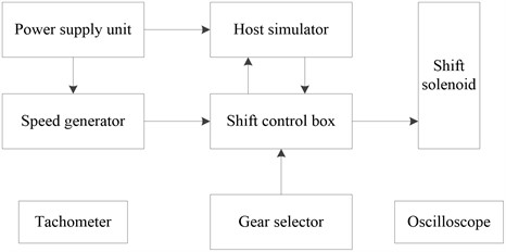
The field experiment is shown in Fig. 8. The figure was taken by author in Wuxi, Jiangsu, China. It shows a self-made simulation system of the automotive mechanical automatic transmission system based on torsional vibration reduction, which is mainly composed of power supply unit, speed generator, host simulator, tachometer, shift control box, oscilloscope, gear selector, and shift solenoid.
The composition of the experimental device is shown in Fig. 9.
Fig. 8Scene of field test
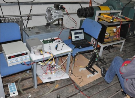
Fig. 9Composition of experimental device
Shift mode selector is a gear selector designed and produced in the development process of automobile mechanical automatic transmission system. The original switch signal is redefined according to the needs of automobile mechanical automatic transmission system mode.
The purpose of speed signal calibration is to obtain the speed coefficient and pulse frequency range. The speed factor is used to calculate the actual speed. The pulse frequency range is used for the design of signal acquisition system, including the design of circuit parameters of each sensor and the setting of relevant parameters of capture timer, and can be used for fault diagnosis of speed sensor. Both the engine speed sensor and the vehicle speed sensor are magnetoelectric speed sensors, and the resistance of the speed sensor is 885 Ω. The output signal waveforms of the two speed sensors are the same. According to the test data, in order to ensure that the output signal amplitude of the sensor is greater than the limit value at low speed, it is necessary to ensure that the gap between the sensor and the gear is less than 4 mm. The amplitude of the output signal of the magnetoelectric speed sensor varies with the speed and flux gap. Table 1 shows the test data of the speed sensor.
Table 1Test data of speed sensor
Clearance / mm | 4 | 5 | 1 | ||||||
Frequency / Hz | 40.49 | 70.92 | 127.4 | 40.85 | 71.05 | 127.4 | 40.69 | 71.17 | 128.4 |
Voltage / V | 2.403 | 2.953 | 5.094 | 6.375 | 7.875 | 11.06 | 16.88 | 24.06 | 19.53 |
3.1. Shift effect comparison
This module takes the target position as the input and the actual position as the output to run the auto mechanical automatic transmission system, and the simulation curve is obtained as shown in Fig. 10.
It can be seen from the figure that compared with the Reference [5] system and the Reference [6] system, the gear selection time of the system in this paper is between 0.2 s-0.3 s and the gear shift time is between 0.3 s-0.4 s, which shows that the time used in the gear selection and shift process of the automotive mechanical automatic transmission system based on torsional vibration reduction designed in this paper basically meets the design requirements and the selected parameters are basically reasonable.
Fig. 10Response curve
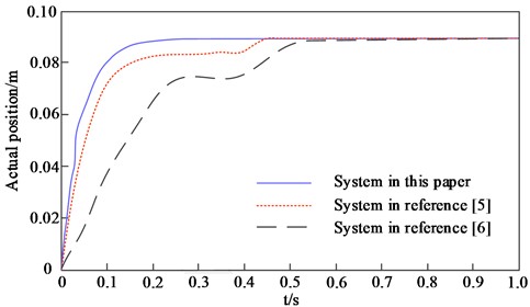
a) Response curve of selected motor
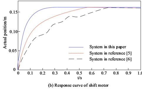
b) Response curve of shift motor
3.2. Speed comparison
The comparison results between the speed of different systems and the expected speed are shown in Table 2.
By analyzing the data in Table 2, it can be seen that there is a certain gap between the vehicle speed and the expected speed under the application of the Reference [5] system, so it is proved that the effect of the vehicle mechanical automatic transmission of the system is poor. Compared with the Reference [5] system, there is a large gap between the vehicle speed and the expected speed under the application of the Reference [6] system, so it is proved that the effect of the vehicle mechanical automatic transmission of the system is poor. Compared with Reference [5] system and Reference [6] system, the gap between vehicle speed and expected speed under the application of this system is small, so it is proved that the effect of vehicle mechanical automatic transmission of this system is better.
Table 2Speed comparison results
Square wave frequency / Hz | Desired speed (r/min) | Speed in reference [5] (r/min) | Speed in reference [6] (r/min) | Speed in this paper (r/min) |
0 | 0 | 0 | 0 | 0 |
100 | 200 | 209 | 235 | 201 |
200 | 400 | 411 | 487 | 103 |
300 | 600 | 623 | 625 | 601 |
400 | 800 | 815 | 868 | 802 |
500 | 1000 | 1036 | 1089 | 1003 |
600 | 1200 | 1289 | 1237 | 1202 |
700 | 1400 | 1497 | 1456 | 1402 |
800 | 1600 | 1687 | 1678 | 1601 |
900 | 1800 | 1836 | 1867 | 1801 |
1000 | 2000 | 2017 | 2058 | 2001 |
3.3. Speed control effect
The speed control effects of different systems are compared, and the results are shown in Table 3.
Table 3Speed control effect
Mileage / km | Expected speed / (km/h) | Speed in reference [5] (km/h) | Speed in reference [6] (km/h) | Speed in this paper (km/h) |
0 | 0 | 0 | 0 | 0 |
10 | 60.5 | 65.3 | 70.2 | 60.8 |
20 | 72.3 | 79.6 | 75.6 | 72.5 |
30 | 75.6 | 76.8 | 80.6 | 78.8 |
40 | 78.8 | 80.6 | 87.9 | 78.9 |
50 | 85.6 | 86.9 | 88.9 | 85.7 |
60 | 87.9 | 90.4 | 93.4 | 87.4 |
70 | 96.6 | 98.7 | 99.6 | 96.4 |
80 | 114.7 | 116.8 | 110.3 | 114.5 |
90 | 116.8 | 117.6 | 117.4 | 116.5 |
100 | 119.6 | 119.8 | 115.6 | 119.5 |
By analyzing the data in Table 3, it can be seen that with the continuous increase of driving mileage, the expected speed also increases. There is a certain gap between the vehicle speed under the application of Reference [5] system and Reference [6] system and the expected speed, so it is proved that the speed control effect of these two systems is poor. Compared with these two systems, the gap between the vehicle speed and the expected speed under the application of this system is small, and the maximum is no more than 0.5 km/h, which shows that the vehicle speed control effect of this system is better.
4. Conclusions
At present, automobile electronization and automation are becoming the development trend of automobile technology. The degree of automobile automation has become an important symbol to measure the technical level of automobile production in a country. In countries with relatively developed automobile industry, the degree of integration of automobile electronic control technology is higher and higher, and continues to develop to intelligent and networked control. At present, the vast majority of vehicles used in China are still manual transmission. Manual transmission vehicles are easy to make drivers tired and affect driving safety due to frequent shift operation; Different driving technology levels cause great differences in the fuel economy, power and ride comfort of vehicles, so automatic transmission is the goal of people’s long-term pursuit and an important symbol of the development of vehicles to the advanced stage. Therefore, this paper designs a mechanical automatic transmission system of vehicles based on torsional vibration reduction. The results show that the gear selection time of the vehicle is between 0.2 s-0.3 s and the gear shifting time is between 0.3 s-0.4 s when the system is applied. In the comparison of system performance, the gap between the vehicle speed and the expected speed of the method in this experiment is small, and the maximum difference is not more than 0.5 km/h, which is better than the method in the literature, verifying the effectiveness of the system. From the results of practical application and performance comparison, it can be seen that the automatic transmission system designed in the experiment has faster shift time and speed control, better system performance, and can be widely used in the field of vehicle control.
References
-
L. Zhang, Y. Peng, H. Yang, and S. Li, “Defect analysis and innovation design of synchronizer for clutchless automatic mechanical transmission,” Chinese Journal of Mechanical Engineering, Vol. 35, No. 1, pp. 1–17, Dec. 2022, https://doi.org/10.1186/s10033-022-00690-8
-
H. Wang, B. Wang, D. Pi, E. Wang, and X. Wang, “Two-layer structure control of an automatic mechanical transmission clutch during hill start for heavy-duty vehicles,” IEEE Access, Vol. 8, pp. 49617–49628, 2020, https://doi.org/10.1109/access.2020.2979901
-
Z. Sun et al., “Improved decoupling control for a powershift automatic mechanical transmission employing a model-based PID parameter autotuning method,” Actuators, Vol. 9, No. 3, p. 54, Jul. 2020, https://doi.org/10.3390/act9030054
-
A. Z. Zainordin, Z. Mohamed, and F. Ahmad, “The magnetorheological fluid: Testing on automotive braking system,” International Journal of Automotive and Mechanical Engineering, Vol. 18, No. 1, pp. 1–10, 2021.
-
L. X. Zhang, T. G. Jia, and C. Wang, “Design of automobile electronic control automatic transmission system based on single chip microcomputer,” Automation and Instrumentation, Vol. 10, No. 2, pp. 114–117, 2019.
-
J. Q. Zeng, “Mechanical automatic transmission shift intelligent vehicle mechanical automatic transmission system design,” Mechanical Design and Manufacturing Engineering, Vol. 48, No. 1, pp. 47–50, 2019.
-
X. Li, Q. Cao, X. Zhang, and X. Gao, “Research on the influence of backlash and bearing clearance on torsional vibration of pure electric vehicle gear system,” International Journal of Vehicle Noise and Vibration, Vol. 17, No. 3/4, p. 273, 2021, https://doi.org/10.1504/ijvnv.2021.123435
-
J. Ju, Y. Liu, and C. Zhang, “Stability analysis of electromechanical coupling torsional vibration for wheel-side direct-driven transmission system under transmission clearance and motor excitation,” World Electric Vehicle Journal, Vol. 13, No. 3, p. 46, Feb. 2022, https://doi.org/10.3390/wevj13030046
-
V. Manchi and C. Sujatha, “Torsional vibration reduction of rotating shafts for multiple orders using centrifugal double pendulum vibration absorber,” Applied Acoustics, Vol. 174, No. 1, p. 107768, Mar. 2021, https://doi.org/10.1016/j.apacoust.2020.107768
-
R. Hu, G. Zhou, and J. Li, “A nonlinear torsional vibration model of harmonic gear reducer and the effect of various factors on torsional vibration during start and stop,” Journal of Vibration and Control, Vol. 28, pp. 1536–1549, 2022.
-
J.-F. Wei, X.-R. Liu, Luo, Z.-X. Li, and B.-M. Li, “Study on differential mode conducted interference of trigger circuit of high-power thyristors in pulsed power supply,” Journal of Physics: Conference Series, Vol. 1507, No. 7, p. 072007, Apr. 2020, https://doi.org/10.1088/1742-6596/1507/7/072007
-
D. Luo, J. Lei, M. Zhang, and Z. Wang, “Design of a low noise bio-potential recorder with high tolerance to power-line interference under 0.8 V power supply,” IEEE Transactions on Biomedical Circuits and Systems, Vol. 14, No. 6, pp. 1421–1430, Dec. 2020, https://doi.org/10.1109/tbcas.2020.3038632
-
X. Liu, Z. Yao, and M. Lu, “Robust time-hopping pseudolite signal acquisition method based on dynamic Bayesian network,” GPS Solutions, Vol. 25, No. 2, pp. 1–14, Apr. 2021, https://doi.org/10.1007/s10291-020-01066-y
-
A. Murali, H. K. Kakarla, and G. M. Anitha Priyadarshini, “Improved design debugging architecture using low power serial communication protocols for signal processing applications,” International Journal of Speech Technology, Vol. 24, No. 2, pp. 291–302, Jun. 2021, https://doi.org/10.1007/s10772-020-09784-x
-
S. Zheng, S. Chen, and X. Yang, “DeepReceiver: a deep learning-based intelligent receiver for wireless communications in the physical layer,” IEEE Transactions on Cognitive Communications and Networking, Vol. 7, No. 1, pp. 5–20, Mar. 2021, https://doi.org/10.1109/tccn.2020.3018736
-
X. L. Sun, H. L. Shen, L. K. Yang, and X. Y. Cao, “Research on characteristics of three? Motor servo control system based on fuzzy control,” Electronic Design Engineering, Vol. 30, No. 1, pp. 117–120, 2022, https://doi.org/10.14022/j.issn1674-6236.2022.01.025
-
D. Wang, W. Zhang, and M. Jiang, “Effect of semi-active HDS on vehicle longitudinal vibration and shock in the process of in-situ shift with different shift time,” Advances in Mechanical Engineering, Vol. 13, No. 2, pp. 395–404, 2021.
-
M. Sága, M. Vaško, Z. Ságová, L. Jakubovičová, and M. Handrik, “Numerical study of the vertical vibration of a vehicle model with variable speed,” in IOP Conference Series: Materials Science and Engineering, Vol. 1199, No. 1, p. 012087, Nov. 2021, https://doi.org/10.1088/1757-899x/1199/1/012087
-
Y. X. Zhang and C. Liu, “Vehicle location method based on neural network and roadside unit fingerprint,” Computer Simulation, Vol. 39, No. 4, pp. 114–118, 2020.
About this article

The research is supported by: “Qinglan Project” funding project of Jiangsu Colleges and universities (No. 3, [2019]); Research Project of professor or doctor in Wuxi Institute of Technology (BT2020-10).
The datasets generated during and/or analyzed during the current study are available from the corresponding author on reasonable request.
The authors declare that they have no conflict of interest.
