Abstract
The present paper considers a multi-criteria analysis algorithm of turbo generator fluid-film bearing operability and its connection with rotor machine monitoring system data. It is substantiated that implementation of predictive analysis of load capacity, locus curves and dynamic displacements allows prognosis of useful life of a fluid-film bearings and improvement of reliability of a rotor machine.
1. Introduction
One of the key components of a power plant is a turbogenerator. Ensuring its reliable and safe operation is a priority, the downtime of such equipment leads to significant costs and underproduction of energy. Compensation of under-generated energy, as a rule, is carried out by transferring workable equipment to a higher than nominal operating mode, which, in turn, leads to an increase in dynamic and thermal loads on critical components of a turbogenerator: rotor, stator, fluid-film bearings (FFB), seals, etc. [1-6].
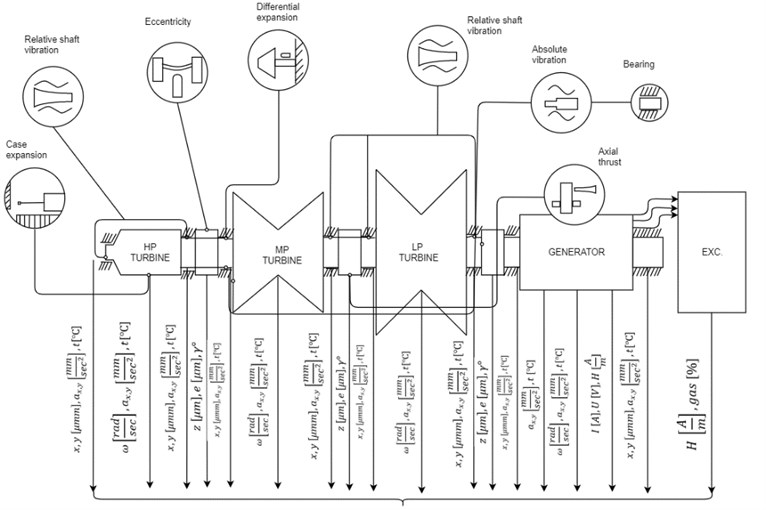
Modern systems for monitoring and diagnostics of turbogenerators use, basically, classical spectral analysis of the signal of vibration displacement sensors [7-10], monitoring of other parameters of the turbogenerator (partial discharges, current, voltage, gas content, pressure, temperature) is carried out according to the nominal signal of the sensors and its comparison with the limiting characteristics. A turbogenerator is a complex multi-parameter system (Fig. 1) in which interconnected electromagnetic, thermal, hydrodynamic, mechanical processes take place, for example, in a gas turbine unit GE LM6000, more than 6000 parameters are simultaneously controlled [11].
Such an analysis is not always effective, since the process of the controlled parameters going beyond the set limits actually means the beginning of the emergency process of the technical system, followed by a stop and the subsequent determination of the causes of failures and their exclusion during repair work. An exception is the system of intelligent forecasting of a healthy state based on multivariate statistical analysis using machine learning methods, for example: Predictive system PRANA [12]; Plant Monitor – Siemens [13]; Predix – GE [14].
These systems are a natural evolution of existing monitoring and diagnostic systems, based on the development of the Internet of things, artificial neural networks and machine learning. But in fact, these systems collect data about the signals from the sensors, compare them with the reference settings and give a forecast about what can happen to the equipment based on the statistics of previous failures and emergency cases. At the same time, the responsibility for bringing the turbogenerator into repair lies with the director of the power plant – prognostic results are basic knowledge that should be verified by experts and the relevant services of the power plant.
Fig. 1Turbogenerator as a multi-parameter monitoring system
2. Predictive model for FFB operability analysis
Predictive analysis, in the authors’ understanding, means a deeper interpretation of the monitoring system signal by using it as input in mathematical models that describe processes in critical nodes of a turbogenerator based on a model-based approach [15].
As an example, we will develop a model for predictive analysis of the operability of the FFB based on the measured parameters of the temperature of the lubricant at the outlet of the FFB with sensors that all turbo generator monitoring systems are equipped with. Typical types of failures of the FFB of a turbogenerator are wear of the antifriction layer, misalignment of bearings, loss of lubricity of a lubricant, and a change in geometric characteristics due to uneven thermal loads.
Fig. 2 shows a block diagram of a multicriteria analysis of the operability of the FFB by the signal of the oil temperature at the input and output of the sliding bearing. The predictive analysis is based on a mathematical model of the FFB, which allows calculating its main characteristics: load capacity, friction moment, lubricant consumption, temperature field distribution, stiffness and damping coefficients, as well as additional dependences of lubricant viscosity on pressure and temperature [16-18].
Fig. 2The block diagram of a multicriteria analysis of the operability of the FFB by a temperature parameter
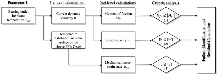
The essence of multicriteria analysis is to maximize the use of signals from the monitoring system in simulation models of processes that are associated with a particular type of failure. An important issue is also the establishment of criteria with respect to which a conclusion should be made about the predicted failure. For example, based on the readings of oil temperature sensors, it is possible to calculate the averaged dynamic viscosity, calculate the bearing capacity of a sliding bearing, and determine the temperature distribution over the surface of the bearing sleeve. Not all calculated parameters allow you to immediately conduct a criterial analysis and require further calculation. For example, knowledge of the current viscosity of the oil does not give an answer to the question of satisfactory sliding operability, but by calculating the friction moment or the coefficient of friction or for greater convenience to estimate the friction power loss, we can estimate how much the current frictional state differs from the initial one. And if the condition is not fulfilled, then this suggests one or more versions of failures, for example, the friction moment may increase due to the transition from the hydrodynamic friction mode to the semi-fluid friction mode or due to wear of the antifriction layer of the plain bearing sleeve. Using this approach, it is possible to solve specific problems that sometimes do not have obvious solutions. For example, by calculating the temperature distribution over the surface of the FFB sleeve, it is possible to calculate the stress-strain state considering local temperature changes and determine the likelihood of a crack. Such a task may be relevant for FFB operating under conditions of large temperature differences during start-stop periods and made of materials with high brittleness, for example, silicon carbide FFB in pumps for pumping oil and gas products in regions with low average daily temperatures.
In order to determine what kind of failure is still most likely, verification of the following criterion is required – ensuring sufficient load capacity. For example, if the current load capacity is sufficient, and the friction moment is high, then we are talking about the wear of the antifriction layer, and if the load capacity is insufficient and the friction moment is high, then it is logical to assume the operation in the semi-fluid friction mode. To clarify this type of failure, it is necessary to solve the direct problem of rotor dynamics and compare the real eccentricity with the permissible one. At this stage, the module for analysis of rotor movements in the clearance of the sliding bearing should be connected according to the monitoring system. That is, such block diagrams can be constructed for each signal and determining the interconnections and conjugation conditions between each criterion is a separate complex task.
3. Predictive model for bearing operability analysis
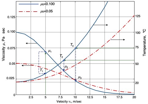
The figures below show the sequence of actions in the predictive analysis system. In the first iteration, it is proposed to use sufficiently proven dependencies to reduce the computational load. Fig. 3 shows the dynamic viscosity of oils with different initial value and temperature in the lubricant layer on sliding speed . The temperature in the lubricating layer, depending on the sliding speed, is determined Eq. (1) [19]:
where is the thermal conductivity of the lubricant (Wm-1K-1).
To account for changes in the thermophysical properties of the lubricant, a function is adopted that relates viscosity and density to temperature and pressure for oils [20]:
where is the temperature viscosity coefficient of the lubricant, the pressure-viscosity coefficient and the viscosity at room temperature and ambient pressure.
For most oils, you can take 0.14 Wm-1K-1, 0.028 K-1.
The diagram allows you to trace the mutual relationship of the influence of temperature factors and sliding speed on the current viscosity of the lubricant and it is convenient to associate this parameter with the readings of the temperature sensor at the bearing exit.
We consider two cases of a change in the viscosity of the lubricant as a result of heating to temperature under the action of friction for a model plain bearing with parameters: diameter 40 mm, length 40 mm, radial clearance 40 μm, angular velocity 250 rad/s, sliding speed 5 m/s, fluid lubrication with an initial viscosity of 0.1 Pa·s. Suppose that in the first case, the liquid temperature sensor at the outlet of the bearing shows the value 55 °С, and in the second case, 75 °С (Fig. 3). The reason for this heating may be the technological processes of rotary machines, increased friction – that is, those factors that are not considered by Eq. (1).
Fig. 3Dynamic viscosity of oils as a function of sliding speed and temperature
The mathematical model of the sliding bearing allows you to calculate the current load capacity and compare it with the required (Fig. 4) in order to achieve the condition Eq. (2).
For example, for viscosity we have that the required load capacity , determined by the weight of the rotor and dynamic loads, is achieved at a relative eccentricity 0.61. After heating the oil to a temperature of 55 °C and dropping the viscosity to , the required load capacity will be achieved at a relative eccentricity 0.69, and when heated to 70 °C for viscosity at a relative eccentricity 0.77. When this occurs, situations that are different for analysis depend on the geometric characteristics and surface treatment conditions.
Fig. 4The dependence of the load on the relative eccentricity
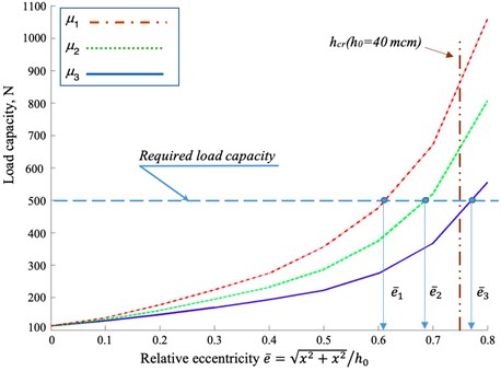
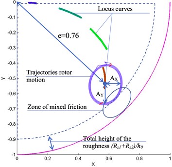
In the first case, an increase in eccentricity does not exceed the limit relative eccentricity, which is determined by the margin of the minimum thickness of the lubricant layer . A decrease in viscosity in the second case leads to the achievement of a given load capacity already beyond the zone of critical relative eccentricity . At the same time, from the point of view of a classical evaluation of the operability of the FFB, this means going beyond critical boundaries and requires measures, but from the point of view of predictive analysis, this means the need for further verification. For example, by solving the equations of motion of the rotor, taking as the perturbing forces only the rotor weight forces Eq. (6), it is possible to construct mobile equilibrium curves to determine the position of the center of mass of the rotor, and then apply the values of the dynamic amplitudes of vibrations to check whether the rotor falls into the boundary or not (Fig. 5) according to the readings of the vibration sensors of the monitoring system or by solving the equations of rotor dynamics Eq. (4), taking as external forces, in addition to the forces of weight and inertia, it is possible to construct rotor movements and evaluate whether the rotor amplitude of the critical eccentricity will not exceed the amplitude of the rotor, that is, will there be semi-liquid or semi-dry friction at a certain phase of the rotor precession motion, as a result of which increased wear of the sliding bearing sleeve will occur (Fig. 5):
where is the mass of rotor, is the unbalance, is the angular velocity, , is the axle bearing capacity (load capacity ).
After checking all the criteria, it can be concluded that the sliding bearing is moving to what type of failure. In fact, the shift to the region of large eccentricities is not a failure, but work in the mixed friction zone will lead to wear of the bearing and, by connecting a mathematical model for determining sleeve wear, we can predict the residual life of the bearing assembly compared to the initial one [21].
Fig. 5Predictive analysis of dynamic characteristics
4. Conclusions
Each failure or emergency of a rotary machine can be detailed in n steps. Each scenario requires its own computational algorithm and its own verified model. If we consider the turbogenerator of a power plant, then the key nodes as the objects of analysis are the rotor, stator, bearings, seals, brush-contact apparatus, pathogen, cooling system.
For example, it is possible to solve the inverse problem of rotor dynamics by supplying rotor displacement as input data from the monitoring system and determining the inertial force and comparing it with the initial values after balancing. This solution will allow you to compare the current value of the inertial forces with the initial one after balancing the rotary machine and make a forecast about undesirable changes, for example, the separation of the impeller blades of the turbine, the compressor or the offset of the balancing weights due to creep.
Each failure scenario should be mathematically formalized by the steps of its occurrence in order to build a global predictive model for analyzing the health of rotor machines. To solve the problem of simultaneous processing of a large amount of data, it is necessary to use modern methods of machine learning and the use of artificial neural networks to process signals from the monitoring and forecasting systems [22].
References
-
Parida N., Tarafder S. Failure analysis of turbo-generator of a 10 MW captive power plant. Engineering Failure Analysis, Vol. 8, Issue 3, 2001, p. 303-309.
-
Csaba G. Generator diagnostics: from failure modes to risk for forced outage. IRMC 2018, Long Beach, 2018.
-
Samorodov Y. N. Turbo Generators: Accidents and Incidents. Reference book. ELEKS-KM, Moscow, 2008, (in Russian).
-
Rostik G. V. Assessment of the Technical Condition of Turbogenerators: a Training Manual. IPKgosluzhby, Moscow, 2008, (in Russian).
-
Puzakov S. E., et al. Handbook for Repair of Turbogenerators. IPKgosluzhby, VIPKenergo, 2006, (in Russian).
-
Vardar N., Ekerim A. Failure analysis of gas turbine blades in a thermal power plant. Engineering Failure Analysis, Vol. 14, Issue 4, 2007, p. 743-749.
-
Bentley D. E., et al. Fundamentals of Rotating Machinery Diagnostics. Bentley Pressurized Bearing Press Minden, 2002, p. 726.
-
Kumenko A. I. Condition and prospects of development of systems of diagnostics of a technical condition of generating equipment TPS. Assembling in Mechanical Engineering and Instrument Making, Vol. 2, Issue 91, 2008, p. 25-37.
-
Kumenko A. I., et al. Development of elements of the condition monitoring system of turbo generators of thermal power stations and nuclear power plants. Thermal Engineering, Vol. 8, Issue 64, 2017, p. 559-567.
-
Edwards S., et al. Fault diagnosis of rotating machinery. Shock and Vibration Digest, Vol. 30, Issue 1, 1998, p. 4-13.
-
Aeroderivative Gas Turbine LM 6000, https://www.ge.com/power/gas/gas-turbines/lm6000.
-
Predictive Analytics and Remote Monitoring System, https://prana-system.com.
-
Condition Monitoring and Machinery Protection, https://new.siemens.com/global/en/products/energy /services/digital-services/diagnostic-monitoring-protection.html.
-
The Industrial IoT Platform, https://www.predix.io.
-
Abdel-Magied M., et al. Fault detection and diagnosis for rotating machinery: a model-based approach. Proceedings of the 1998 American Control Conference, Vol. 6, 1998, p. 3291-3296.
-
Polyakov R. N., et al. Dynamics of the multimass rotor on active hybrid bearings. Proceedings of the ECOMAS Thematic Conference on Multibody Dynamics, 2015.
-
Kornaev A., et al. Influence of the ultrafine oil additives on friction and vibration in journal bearings. Tribology International, Vol. 101, 2016, p. 131-140.
-
Savin L., et al. Hydrodynamic effects influence on lateral vibrations of rigid symmetric rotor with fluid-film bearings. Vibroengineering Procedia, Vol. 8, Issue 2016, 2016, p. 322-327.
-
Greenwood J. A., et al. Inlet shear heating in elasto- hydrodynamic lubrication. ASME Journal of Lubrication Technology, Vol. 95, Issue 4, 1973, p. 417-426.
-
Wensing J. A. On the Dynamics of Ball Bearings. Ph.D. Thesis, University of Twente, Enschede, The Netherlands, 1998, p. 173.
-
Rozeanu L. Wear of hydrodynamic journal bearings. Tribology Series, Vol. 39, 2001, p. 161-166.
-
Kornaeva E. P., et al. Application of artificial neural networks to diagnostics of fluid-film bearing lubrication. IOP Conference Series: Materials Science and Engineering, Vol. 734, 2020, p. 012154.
Cited by
About this article

The work has been carried out within the project No. 05.607.21.0303 “Development of an Intelligent Monitoring Technology and a Prototype of the Hardware and Software Complex for Safety of Energy Complex Facilities” supported by the Federal Target Program “Research and Development in Priority Areas for the Development of the Scientific and Technological Complex of Russia for 2014 – 2020” by the Ministry of Science and Higher Education of Russian Federation (unique identifier of the research RFMEFI60719X0303).
