Abstract
This paper aims at analyzing a preliminary layout for a Hydraulic Interconnected Suspension (HIS) for rail vehicles. The device is intended to replace the primary vertical dampers and its design aims at decoupling the heave and roll responses. HIS solution provides additional tuning possibilities to optimize and refine the primary suspension stage of rail vehicles. A physical numerical model is developed, and the influence of three design parameters on the forces generated by the HIS is studied.
1. Introduction
The demand for higher service speed in high-speed railways has become an undeniable necessity in today's transportation landscape. The high-speed rail industry faces the challenge of enhancing the dynamic performances of its vehicles. The simultaneous goals of achieving higher speeds and ensuring safety and ride comfort present significant challenges for high-speed rail systems, necessitating continuous advancements in suspension technology [1]-[5].
Research & Development on hydraulic suspension elements is crucial to achieving high performance without introducing safety-related concerns like overturning due to the extreme rolling motion, which can occur during curve negotiation, parallel train interaction, or strong crosswinds encounter. The Hydraulic Interconnected Suspension (HIS) is one of the promising suspension layouts in rail engineering applications. It can improve the roll performance preserving the ride comfort, thanks to their ability in decoupling the roll and heave modes [6]. Active HIS schemes have been studied to improve the roll and lateral dynamics of the rail vehicles in [7] at the secondary suspension stage (i.e., the suspension stage connecting the car body to the bogie frames) by actively tilting the train when the vehicle negotiates a curve. Employing an active HIS scheme at the secondary suspension stage allows for the replacement of the passive anti-roll bar, although it requires a solid control strategy, and energy consumption. The study of HIS’ potential, when applied to the primary suspension stage (i.e. the suspension stage connecting the bogie frame to the wheelsets), is still an open issue. Indeed, HIS layouts guarantee additional tuning possibilities for the primary suspension stage, a relevant feature when dealing with ride comfort performances, as reported in [8], [9]. Nevertheless, the use of such system on primary suspension stages of rail vehicles has been rarely reported.
In this context, this paper proposes a design of a passive HIS scheme that is placed at the primary suspension stage. The proposed layout is intended to replace passive vertical dampers. It aims at offering greater possibilities in suspension tuning due to the decoupling between heave and roll responses of the primary suspension stage and easier implementation of semi-active and active configurations to further improve vehicle performances.
2. Hydraulic interconnected suspension modelling
The most frequently claimed advantage of the interconnecting wheel stations is that it provides the suspension designer with more control over the stiffness and damping of each suspension mode [10], [11]. The HIS system distributes fluid flow to dampers and valves based on the specific suspension mode being utilized. In the heave mode, fluid exits one of the chambers of each cylinder and flows into the cross-diagonal chamber. Instead in the roll mode, chambers in one circuit have fluid flowing into them while chambers in the other circuit have fluid flowing out. Damper valves are implemented to create local losses resulting in pressure differences, allowing the system to dissipate energy. In the heave mode, higher dissipation is desired, while the roll mode requires stiffness. The schematic diagram of the HIS is shown in Fig. 1.
Fig. 1Schematic diagram of the HIS
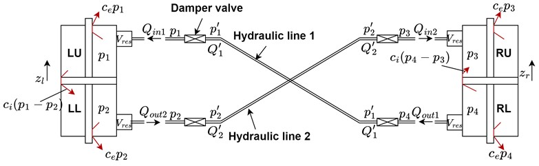
The mathematical model of the HIS proposed in this paper is developed considering the assumptions suggested for similar devices by previous research works, such as [7]. Considering mass conservation for each chamber under the assumption of partially compressible fluid results in the following equations:
where , , and A are the nominal volume of the chambers, reservoir volume, and effective piston area, which is calculated by subtracting rod area from the piston area. , , , and are the fluid flow rates, and and are the internal and external leakage coefficients respectively. Chamber pressures are , , , and for left upper (LU), left lower (LL), right upper (RU), and right lower (RL). And finally, , , , and represent left and right piston displacements and left and right piston speeds respectively.
The damper valves play a key role in the HIS system, and they usually feature nonlinear pressure-flow characteristics [7]. In this paper, the simplified model assumes that the damper valves have negligible fluid volume and involve linear pressure losses. Also considering the mass conservation, it results in the following equations:
where is the damper valve loss coefficient, , and are the fluid flow rates for hydraulic lines 1 and 2, respectively. Finally, , and are the pressures in hydraulic lines 1 and 2. Considering the assumption for the pipes, and merging Eq. (5) and Eq. (8) results in:
Similarly:
is obtained by merging Eq. (6) and Eq. (7). Replacing Eqs. (5-8) and Eqs. (9-10) in Eq. (1-4) and neglecting external leakage contribution the following equations for pressure variations can be obtained:
By integrating Eqs. (11-14) over time, pressures for each chamber can be obtained. Left and right damper forces can be calculated as:
The governing equations of the HIS model are then implemented in Simulink. Sine waves are generated to represent left and right dampers’ motion with different frequencies as suggested by the standard [12]. To simulate heave motion, the phase between two signals is set to zero while, to simulate roll motion, it is set to 180°. Thanks to the decoupling effect of the HIS, different behaviors in two modes can be obtained. Indeed, the pure roll response of the HIS is characterized by a phase between the forces of the left and right cylinders, resulting in an additional roll stiffness. On the other hand, the left and the right cylinders provide a synchronous action to the heave response of the HIS. Replacing the primary vertical dampers with a HIS device could allow the softening of the primary vertical springs of the vehicle, to improve ride comfort performances [8], [9]. At the same time, the use of a HIS set up with a sufficiently high roll stiffness could compensate the reduced limiting effect of softer primary springs on the vehicle rolling. Moreover, the HIS layout would allow additional flexibility in the tuning of the primary vertical damping of the primary suspension stage. This would enable the design of a primary suspension stage for rail bogies able to alleviate the typical trade-off between soft and stiff spring stiffness.
In the following section, the variation of the HIS responses due to the modification of damper valve loss coefficient (), internal leakage coefficient (), and reservoir volume () will be studied to understand their effect on the suspension behaviors both for roll and heave modes.
3. Results
3.1. Roll performance
In the roll mode, an emphasis is placed on suspension stiffness rather than its dissipative characteristic. Due to their effects on the roll stiffness, reservoir volume, and internal leakage coefficient are selected as design variables. Moreover, it can be demonstrated that the damper valve loss coefficient does not affect the roll stiffness of the suspension.
3.2. Effect of reservoir volume on roll performance
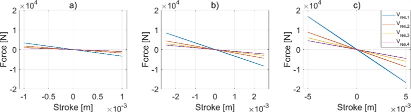
Reservoir volume is varied to obtain different roll stiffness values for the suspension. Increased reservoir volume results in a decrease of the suspension roll stiffness as shown in Fig. 2, where the force of the left cylinder is reported as function of the imposed displacement. To understand the effect of the reservoir volume, the HIS is simulated with different strokes while the reservoir volume is increased, and the internal leakage coefficient and damper valve loss coefficient are kept constant. The increase in the overall chamber volume is leading to a softer response of the suspension increasing the overall anti-roll torque. Moreover, it can be noted that the response provided by the HIS featuring a small value is almost completely elastic.
Fig. 2Effect of reservoir volume on the suspension behavior in roll mode. a) 1 mm of stroke, b) 2.5 mm of stroke, c) 5 mm of stroke. Results obtained by considering Vres,1= 9.8 e-3 m3, Vres,2= 1.2 e-2 m3, Vres,3= 2.9 e-2 m3, Vres,4= 3.9 e-2 m3
3.3. Effect of internal leakage coefficient on roll performance
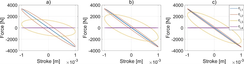
The internal leakage effect on the suspension is studied by selecting three different frequencies and varying the internal leakage coefficient while keeping the reservoir volume, damper valve loss coefficient, and stroke fixed for these three frequencies.
In Fig. 3, it can be seen that suspension displays more dissipative behavior with increased internal leakage coefficient values, and this effect is more pronounced at lower frequencies. Therefore, the parameter plays a significant role in the dissipative contribution of the HIS’ roll response. Internal leakages introduce an energy dissipation that could lead to positive effects in vibration transmission to the bogies, but too-high values invalidate the overall response of the component, reducing the roll stiffness.
3.4. Heave performance
The dissipative characteristic of the suspension is crucial in the heave mode and for the HIS system this is mainly governed by the damper valves. Furthermore, the internal leakage coefficient also determines the dissipative behavior of the suspension since it is a direct representation of fluid leakage within suspension chambers.
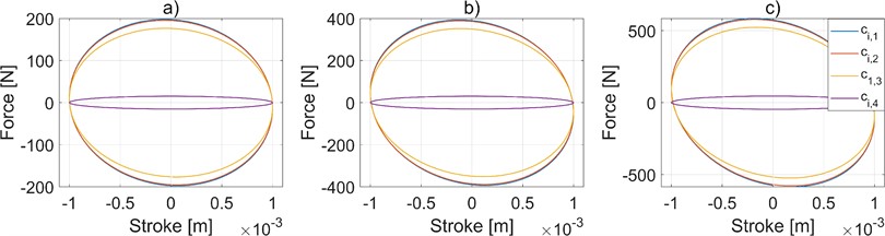
Fig. 3Effect of internal leakage coefficient on the suspension behavior in roll mode. a) 1.59 Hz of frequency, b) 3.18 Hz of frequency, c) 4.77 Hz of frequency. Results obtained by considering ci,1= 1 e-18 m3/Pa, ci,2= 1 e-11 m3/Pa, ci,3= 1 e-10 m3/Pa, ci,4= 1 e-8 m3/Pa
3.5. Effect of damper valve loss coefficient on heave performance
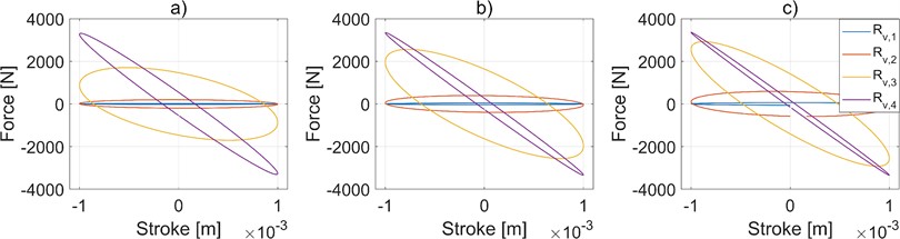
Variations in the damper valve loss coefficient result in distinct changes in the suspension response. To understand its effect, at the frequencies selected in the previous section, the HIS is simulated with constant reservoir volume and internal leakage coefficient while the damper valve loss coefficient is varied.
As can be seen in Fig. 4, higher values of the damper valve loss coefficient increase the damping force, which may lead to pronounced vibration attenuation and improved ride comfort. On the other hand, it is also seen that suspension layouts with higher values tend to increase the elastic contribution of the HIS response with respect to lower settings.
Fig. 4Effect of damper valve loss coefficient on the suspension behavior in heave mode. a) 1.59 Hz of frequency, b) 3.18 Hz of frequency, c) 4.77 Hz of frequency. Results obtained by considering RV,1= 6 e7 kgs-1 m-4, RV,2= 6 e8 kgs-1 m-4, RV,3= 6 e9 kgs-1 m-4, RV,4= 6 e10 kgs-1 m-4
3.6. Effect of internal leakage coefficient on heave performance
The effect of the internal leakage coefficient is studied by varying its value while keeping the reservoir volume and damper valve loss coefficient constant at different frequencies. Fig. 5 shows the characterization cycles for heave mode at different frequencies with varied internal leakage values.
The detrimental action of a too-high internal leakage, already shown in Fig. 3, is confirmed. Indeed, it can be understood that significant internal leakage invalidates the overall response of the HIS device. However, it is worth noting in Fig. 5 the presence of a range of in which this parameter is not affecting the heave response. Therefore, it can be stated that within this range the value can be tuned just according to the desired roll response of the HIS device.
Fig. 5Effect of internal leakage coefficient on suspension behavior in heave mode. a) 1.59 Hz of frequency, b) 3.18 Hz of frequency, c) 4.77 Hz of frequency. Results obtained by considering ci,1= 1 e-18 m3/Pa, ci,2= 1 e-11 m3/Pa, ci,3= 1 e-10 m3/Pa, ci,4= 1 e-8 m3/Pa
4. Conclusions
In this paper, a passive Hydraulic Interconnected Suspension (HIS) for the primary suspension stage of rail vehicles has been analyzed. The device has been designed to replace conventional vertical dampers and to decouple the responses to heave and roll excitations, offering more tuning possibilities than standard suspension components. A fluid dynamic numerical model describing the four chambers of the HIS has been developed in Simulink. The responses of the HIS device to heave and roll excitations have been analyzed considering the reservoir volume, internal leakage coefficient, and damper valve loss coefficient. The numerical simulations proved that the elastic and the dissipative contributions of both responses can be independently varied by modifying the three design parameters proposed in this paper. As future steps, multibody co-simulations can be set up to quantify the influence of the proposed HIS scheme on the dynamics of a rail vehicle.
The physical prototyping of the optimal HIS layout would require a proper design of the hydraulic lines in terms of pipes and valves. This is required to match the design damping properties of the HIS during heave motion. Experimental tests would be required to validate the HIS design, to guarantee the expected performances.
The economical investment to study and design an HIS device is relevant. Nevertheless, it is important to consider that such solution could allow bogie manufacturers to alleviate some of the trade-offs that are typically faced during the optimization of the suspension components of these systems. Moreover, the HIS can be easily modified by adding controlled valves and hydraulic pumps: indeed, the passive HIS layout can be considered as a starting product to be improved in the future by introducing semi-active or active architectures.
References
-
F. Ripamonti and A. Chiarabaglio, “A smart solution for improving ride comfort in high-speed railway vehicles,” Journal of Vibration and Control, Vol. 25, No. 13, pp. 1958–1973, Jul. 2019, https://doi.org/10.1177/1077546319843377
-
G. Isacchi, F. Ripamonti, M. Corsi, and T. van Dongen, “A smart passive yaw damper for the reduction of lateral contact forces in low-radius curved tracks,” in 15th World Congress on Computational Mechanics & 8th Asian Pacific Congress on Computational Mechanics, 2022.
-
F. Ripamonti, A. Chiarabaglio, and F. Resta, “A semi-active damper in vertical secondary suspension for the comfort increase in passenger trains,” in SPIE Smart Structures and Materials + Nondestructive Evaluation and Health Monitoring, Vol. 10164, pp. 744–754, Apr. 2017, https://doi.org/10.1117/12.2258225
-
G. Isacchi, F. Ripamonti, and M. Corsi, “Innovative passive yaw damper to increase the stability and curve-taking performance of high-speed railway vehicles,” Vehicle System Dynamics, Vol. 61, No. 9, pp. 2273–2291, Sep. 2023, https://doi.org/10.1080/00423114.2022.2105242
-
G. Isacchi, F. Ripamonti, and M. Corsi, “A meta-heuristic optimization procedure for the identification of the nonlinear model parameters of hydraulic dampers based on experimental dataset of real working conditions,” Journal of Computational and Nonlinear Dynamics, Vol. 18, No. 9, Sep. 2023, https://doi.org/10.1115/1.4062541
-
J. Zou, X. Guo, M. A. A. Abdelkareem, L. Xu, and J. Zhang, “Modelling and ride analysis of a hydraulic interconnected suspension based on the hydraulic energy regenerative shock absorbers,” Mechanical Systems and Signal Processing, Vol. 127, pp. 345–369, Jul. 2019, https://doi.org/10.1016/j.ymssp.2019.02.047
-
E. F. Colombo, E. Di Gialleonardo, A. Facchinetti, and S. Bruni, “Active carbody roll control in railway vehicles using hydraulic actuation,” Control Engineering Practice, Vol. 31, pp. 24–34, Oct. 2014, https://doi.org/10.1016/j.conengprac.2014.05.010
-
J. Wu and Y. Qiu, “Modelling and ride comfort analysis of a coupled track-train-seat-human model with lateral, vertical and roll vibrations,” Vehicle System Dynamics, Vol. 60, No. 9, pp. 2988–3023, Sep. 2022, https://doi.org/10.1080/00423114.2021.1933088
-
S. Steišūnas, J. Dižo, G. Bureika, and V. Žuraulis, “Examination of vertical dynamics of passenger car with wheel flat considering suspension parameters,” Procedia Engineering, Vol. 187, pp. 235–241, 2017, https://doi.org/10.1016/j.proeng.2017.04.370
-
N. Zhang, W. A. Smith, and J. Jeyakumaran, “Hydraulically interconnected vehicle suspension: background and modelling,” Vehicle System Dynamics, Vol. 48, No. 1, pp. 17–40, Jan. 2010, https://doi.org/10.1080/00423110903243182
-
W. A. Smith, N. Zhang, and W. Hu, “Hydraulically interconnected vehicle suspension: handling performance,” Vehicle System Dynamics, Vol. 49, No. 1-2, pp. 87–106, Feb. 2011, https://doi.org/10.1080/00423111003596743
-
“EN 13802 Railway applications – Suspension components – Hydraulic dampers,” BSI Standards Limited, 2013.
About this article

The authors have not disclosed any funding.
The datasets generated during and/or analyzed during the current study are available from the corresponding author on reasonable request.
The authors declare that they have no conflict of interest.
