Abstract
High-speed rail vehicles are equipped with yaw dampers to avoid the arising of hunting motion when running at high-speed. Although these suspension components provide a stabilizing effect on the vehicles, they also influence the ride comfort performances by affecting the accelerations perceived by the passengers. In this context, this paper aims to correlate the installation angle on the vertical plane of such suspension components on the ride comfort performances of a generic high-speed train. The proposed methodology is based on multibody simulations of a model with deformable car body. The modal behavior of the model is aligned to the typical mode shapes and natural frequencies reported in literature.
1. Introduction
Nowadays, the competitiveness of rail transport systems is being improved by arising the commercial speed of the vehicles. This introduces new challenges in the design of safe and comfortable trains. Indeed, running stability is strongly influenced by the speed, as well as ride comfort performance. In the last years a lot of research efforts have been devoted to the design and optimization of suspension components for improving the ride comfort performance of high-speed trains. Secondary vertical and lateral suspensions to suppress the accelerations perceived by passengers on the car body have been studied [1-3]. Regarding yaw damper, huge attention has been focused on the design of suspension components to provide superior stability performance, considering also their influence on the curve negotiation of rail vehicles [4-7]. However, yaw dampers also affect the ride comfort performance. Their influence has been investigated through analytical models, as reported in [8-9].
In this context, this paper proposes a more refined numerical methodology to study the influence of yaw damper components on the ride comfort performances of high-speed rail vehicles. A multibody model is designed to simulate the high-speed running condition. The multibody model features a deformable car body to simulate the structural amplifications phenomena due to its flexibility. The numerical procedure is employed to analyze the effect of the yaw dampers mounting angle on the ride comfort performance.
2. Material, methods and models
2.1. Multibody model
Multibody analysis proved to be an effective tool to quantify the dynamic performance of rail vehicles [4, 10], especially considering the variation of the suspension layout. This paper proposes a multibody model of a rail vehicle composed of four rigid wheelsets, two rigid bogies and a flexible car body structure. The mass and moment of inertia parameters of the bodies are reported in Table 1. The model, developed in the Simpack software, is derived from Chinese high-speed trains, therefore the wheel profile S1002CN and rail profile CN60 have been considered. In Table 1, the parameters, of the suspension components in the primary suspension stage have been reported, with the only exception of the nonlinear primary vertical damper, reported in Fig. 1. The secondary suspension stage is based on a set of linear springs and nonlinear hydraulic dampers. The linear stiffness values are summarized in Tab.1, while the nonlinear characteristics of vertical, lateral and yaw dampers of the secondary suspension stage is reported in Fig. 1. The vehicle presents two vertical dampers, two lateral dampers and four yaw dampers for each bogie.
Table 1Main parameters of the multibody model. The x direction is parallel to the track, y represents the transversal direction and z is aligned to the vertical direction
Parameter | Value |
Car body mass, bogie mass, wheelset mass | (33600, 2300, 1550) kg |
Car body moment of inertia | (8.68e4, 1.90e6, 1.91e6) kgm2 |
Primary suspension stiffness | (17.5e6, 8e6, 8e5) N/m |
Primary suspension damping | (1e4, 1e4) Ns/m |
Secondary suspension stiffness | (2.5e5, 2.5e5, 3.0e5) N/m |
Fig. 1Nonlinear characteristic of a) primary vertical dampers, b) lateral secondary dampers, c) vertical secondary dampers, d) yaw dampers
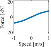
a)
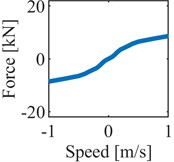
b)
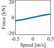
c)
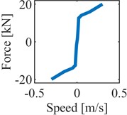
d)
2.2. Car body flexible model
Car body flexibility proved to be a relevant feature in ride comfort assessment of rail vehicles, amplifying the excitation received from track unevenness in the frequency ranges closer to its natural frequencies [11]. For this reason, a flexible car body has been modelled in Abaqus through a finite element approach to be imported in the Simpack multibody model. This interpretative model is intended to simulate the modal behavior of a typical car body of a modern high-speed train. For this reason, special attention has been focused on obtaining natural frequencies and mode shapes aligned with the ones reported in literature. In particular, the natural frequencies of the diamond deformable mode and the first bending modes in vertical and horizontal planes have been compared with the ones reported in [10, 12]. The three main three-dimensional mode shapes and their corresponding natural frequencies have been reported in Fig. 2. The car body model features 33 measurement points on the pavement, and Fig. 2 describes the relationship between the first three deformable mode shapes and the measurement points on the car body. The modal behavior of the multibody model has been analyzed by means of a linearized eigenvalue analysis. The natural frequencies are summarized in Table 2, where the terms related to the main rigid and deformable modes are compared with corresponding values reported in previous research works focused on similar vehicles [13, 14]. The comparison of the natural frequencies of the main mode shapes of the vehicle shows that the multibody model proposed in this paper is aligned to the expected modal behavior of high-speed vehicles.
3. Results
3.1. Ride comfort assessment: NMV index
According to the EN 12299 standard, ride comfort in rail vehicles can be quantified with the Mean Comfort Standard Method considering the NMV performance index. The NMV is processed starting from the Root Mean Square of the car body accelerations. Weighting functions are applied to consider variation of the human beings’ perception of vibrations in the frequency domain. Then, a statistical analysis is implemented considering the measurements from three different points (front, rear and middle car body) along the three directions. Recently, suggestions about improving the robustness of ride comfort assessment considering different measurement locations have been discussed [15]. For this reason, the proposed numerical assessment considers 33 locations distributed on the car body pavement (see Fig. 2) to improve the reliability of the standard numerical analysis focused on the influence of yaw dampers on ride comfort.
Table 2Comparison of the natural frequencies of the multibody model with corresponding values previously reported in literature, for both rigid and deformable modes
Rigid modes | Frequency | Expected frequency (from [13]) |
Car body bounce | 0.87 Hz | 0.90 Hz |
Car body yaw | 0.96 Hz | 1.10 Hz |
Car body pitch | 1.01 Hz | 1.03 Hz |
Bogie bounce | 6.24 Hz | 6.10 Hz |
Deformable modes | Frequency | Expected frequency (from [14]) |
Diamond-skew mode | 9.51 Hz | 9.70 Hz |
1st bending, vertical plane | 12.00 Hz | 11.63 Hz |
1st bending, horizontal plane | 14.01 Hz | 14.16 Hz |
Fig. 2Three-dimensional car body mode shapes related to the first three natural frequencies, with influence of the modal behavior on the 33 measurement points proposed in this papera) Diamond-skew mode, with a natural frequency of 9.51 Hz, b) 1st bending mode on the vertical plane, with a natural frequency of 12.00 Hz, c) 1st bending mode on the horizontal plane with a natural frequency of 14.01 Hz
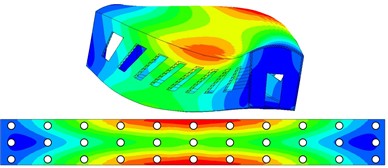
a)
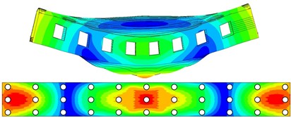
b)
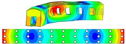
c)
In this paper, the influence of the yaw dampers mounting angle on the ride comfort is evaluated. Multibody simulations of straight track running with a duration of 5 minutes (in accordance with EN 12299) have been performed by varying the yaw damper inclination angle α in the vertical plane from 0° to 10°. Track irregularity in vertical and lateral directions have been considered according to the ERRI B176/DT290 technical report, high level. The vehicle speed has been set equal to 350 km/h.
3.2. Results discussion
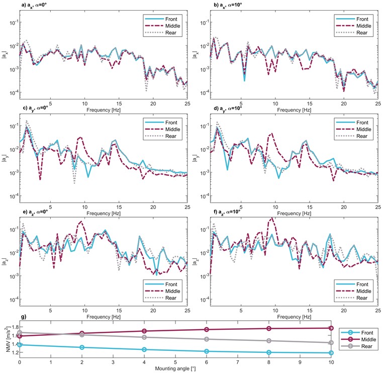
The ride comfort performances evaluated at the 33 measurement points through the NMV index are reported in Fig.3. It can be noticed that modifying the inclination angle of yaw damper components from 0° to 10° leads to a significant variation of the NMV distribution along the car body. Indeed, with 0° the worst area (highest NMV) is located at the rear end of the car body, while the increase of leads to a progressive migration of the worst locations towards the external positions (left and right) at the car body center. The distribution of the NMV values can be compared with the mode shapes of the pavement reported in Fig. 2, noticing that the higher the values of α, the stronger the correlation between the influence of the diamond car body mode and the NVM distribution. Moreover, Fig. 4 reports an analysis in frequency domain of the data obtained from the multibody simulations only limited to the measurement points suggested by EN 12299 (F5 right, M right, R5 left according to Fig. 3) and the limit mounting angles (0° and 10°).
Fig. 3Distribution of the NMV index along the car body pavement for running speed of 350 km/h, considering the vertical mounting angle of yaw dampers between the range [0°-10°]. Comparison of 33 measurement positions distributed along the car body structure
![Distribution of the NMV index along the car body pavement for running speed of 350 km/h, considering the vertical mounting angle of yaw dampers between the range [0°-10°]. Comparison of 33 measurement positions distributed along the car body structure](https://static-01.extrica.com/articles/23531/23531-img8.jpg)
The frequency analysis confirms the previous hypothesis. As shown in Fig. 2, the car body diamond mode is characterized by a coupled deformation in lateral and vertical direction, and the pavement region where this mode has the highest influence is located at the lateral extremities of the central car body pavement. According to Fig. 4, the middle right point shows a stronger contribution about 9.5 Hz in both vertical and lateral direction with respect to the F5 right and R5 left locations. This result is evident for both values of mounting angle, but it becomes more evident for 10° confirming that the relevance of the diamond mode shape on the perceived accelerations increases with the arising of .
The influence of the first bending mode on the vertical plane on the perceived acceleration can be observed in Fig. 3 by comparing the NMV values of the twelve points located at R5, R4, F4 and F5 rows with the modal shapes reported in Fig. 2. It can be noted that this mode excites the central points in these rows more than the lateral external ones, especially at R4 and F4. At the same time, the diamond mode is acting on the opposite way on the same rows, but its effect is less relevant. Therefore, the effect of the vertical bending mode on rows R5, R4, F4 and F5 can still be observed in Fig. 3.
The influence of the lateral bending mode can be observed in Fig. 4(c) and Fig. 4(d) around 14 Hz. However, its effect on the ride comfort assessment is limited with respect to the two other deformable modes.
A general assessment can be done considering also Fig. 4(g), where the increase in the mounting angle of the yaw dampers brings to a progressive migration of the worst performances from the front and rear edges to the center of the car body. From these results, an optimal damper inclination angle could be suggested. Unfortunately, the standard assessment does not provide an overall quantification of the vehicle performance for all the passenger seating and does not allow the understanding of the main modal contributions. Moreover, limiting the focus on the three suggested measuring point can lead to an overestimation of the ride comfort performance, considering that for low installation angle the worst NMV index lays outside from the three positions specified in EN 12299. For these reasons, considering a higher amount of measurement locations on the car body pavement can be considered as a refined and a more consistent way to study the effect on ride comfort performances of suspension components and car body design.
Fig. 4Frequency domain analysis of the perceived acceleration in the front, middle and rear measurement locations specified by EN12299 (points F5 right, M right, R5 left), considering α= 0° and α= 10°. a)-b) Longitudinal direction, c)-d) lateral direction, e)-f) vertical direction, g) Trend of the NMV values for the points selected by EN12299
4. Conclusions
In this paper, a numerical procedure to assess the ride comfort performances of high-speed rail vehicles is presented. A multibody model of a test case vehicle, consisting in four rigid wheelsets, two rigid bogies and a flexible car body is developed. The modal behavior of the numerical model has been aligned to the typical mode shapes and eigenfrequencies presented in literature. A post process approach based on the EN 12299 standard has been proposed, increasing the number of measurement points on the pavement of the car body.
Multibody simulations have been performed to assess the influence of the inclination angle of yaw damper components on the ride comfort performance of the vehicle. The results obtained from the numerical simulations have been correlated with the modal behavior of the car body. It has been shown that increasing the yaw damper mounting angle can lead to a higher excitation of the diamond and vertical bending modes of the car body, modifying the best and worst car body locations in terms of ride comfort.
The present methodology can be considered as a part of a numerical procedure to optimize yaw dampers, able to also consider their influence on the ride comfort, rather than only their effects on vehicle stability and curve-taking performances.
References
-
F. Ripamonti and A. Chiarabaglio, “A smart solution for improving ride comfort in high-speed railway vehicles,” Journal of Vibration and Control, Vol. 25, No. 13, pp. 1958–1973, Jul. 2019, https://doi.org/10.1177/1077546319843377
-
Y. Wu, F. Gan, H. Shi, J. Zeng, C. Chen, and Y. Feng, “Experimental investigations on the semi-active control of a valve-driven secondary lateral damper for a high-speed rail vehicle,” Journal of Vibration and Control, Vol. 29, No. 13-14, pp. 3025–3037, Jul. 2023, https://doi.org/10.1177/10775463221090322
-
F. Ripamonti, A. Chiarabaglio, and F. Resta, “A semi-active damper in vertical secondary suspension for the comfort increase in passenger trains,” in SPIE Smart Structures and Materials + Nondestructive Evaluation and Health Monitoring, Vol. 10164, pp. 744–754, Apr. 2017, https://doi.org/10.1117/12.2258225
-
G. Isacchi, F. Ripamonti, and M. Corsi, “Innovative passive yaw damper to increase the stability and curve-taking performance of high-speed railway vehicles,” Vehicle System Dynamics, Vol. 61, No. 9, pp. 2273–2291, Sep. 2023, https://doi.org/10.1080/00423114.2022.2105242
-
G. Isacchi, F. Ripamonti, and M. Corsi, “A meta-heuristic optimization procedure for the identification of the nonlinear model parameters of hydraulic dampers based on experimental dataset of real working conditions,” Journal of Computational and Nonlinear Dynamics, Vol. 18, No. 9, Sep. 2023, https://doi.org/10.1115/1.4062541
-
S. Alfi, S. Bruni, R. M. Goodall, and C. P. Ward, “Secondary yaw control to improve curving vs. stability trade-off for a railway vehicle,” Vehicle System Dynamics, Vol. 61, No. 5, pp. 1367–1386, May 2023, https://doi.org/10.1080/00423114.2022.2094277
-
G. Isacchi, F. Ripamonti, M. Corsi, and T. van Dongen, “A smart passive yaw damper for the reduction of lateral contact forces in low-radius curved tracks,” in 15th World Congress on Computational Mechanics & 8th Asian Pacific Congress on Computational Mechanics, 2022.
-
M. Dumitriu and D. I. Stănică, “Effect of the anti-yaw damper on car body vertical vibration and ride comfort of railway vehicle,” Applied Sciences, Vol. 10, No. 22, p. 8167, Nov. 2020, https://doi.org/10.3390/app10228167
-
Z. Xia, J. Zhou, D. Gong, W. Sun, and Y. Sun, “Theoretical study on the effect of the anti-yaw damper for rail vehicles,” Proceedings of the Institution of Mechanical Engineers, Part C: Journal of Mechanical Engineering Science, Vol. 234, No. 2, pp. 457–473, Jan. 2020, https://doi.org/10.1177/0954406219878752
-
R. L. Giossi, A. Shipsha, R. Persson, P. Wennhage, and S. Stichel, “Towards the realization of an innovative rail vehicle – active ride comfort control,” Control Engineering Practice, Vol. 129, p. 105346, Dec. 2022, https://doi.org/10.1016/j.conengprac.2022.105346
-
F. Cheli and R. Corradi, “On rail vehicle vibrations induced by track unevenness: Analysis of the excitation mechanism,” Journal of Sound and Vibration, Vol. 330, No. 15, pp. 3744–3765, Jul. 2011, https://doi.org/10.1016/j.jsv.2011.02.025
-
Q. Wang, J. Zeng, L. Wei, and B. Zhu, “Carbody vibrations of high-speed train caused by dynamic unbalance of underframe suspended equipment,” Advances in Mechanical Engineering, Vol. 10, No. 12, p. 168781401881896, Dec. 2018, https://doi.org/10.1177/1687814018818969
-
H. Shi and P. Wu, “Flexible vibration analysis for car body of high-speed EMU,” Journal of Mechanical Science and Technology, Vol. 30, No. 1, pp. 55–66, Jan. 2016, https://doi.org/10.1007/s12206-015-1207-6
-
Y. Sun, J. Zhou, D. Gong, W. Sun, and Z. Xia, “Vibration control of high-speed trains self-excitation under-chassis equipment by HSLDS vibration isolators,” Journal of Mechanical Science and Technology, Vol. 33, No. 1, pp. 65–76, Jan. 2019, https://doi.org/10.1007/s12206-018-1207-4
-
E. Palomares, A. L. Morales, A. J. Nieto, M. Félix, J. M. Chicharro, and P. Pintado, “Is the standard ride comfort index an actual estimation of railway passenger comfort?,” Vehicle System Dynamics, pp. 1–14, Dec. 2022, https://doi.org/10.1080/00423114.2022.2148543
About this article

The authors have not disclosed any funding.
The datasets generated during and/or analyzed during the current study are available from the corresponding author on reasonable request.
The authors declare that they have no conflict of interest.
