Abstract
It is meaningful to understand the effect of inter-vehicle damper and its parameters on high-speed train dynamics in the context of train inter-vehicle suspension design or optimization. In this study, Multi-body System (MBS) dynamics modelling of a high-speed CRH train with inter-vehicle damper is firstly carried out, in which a simplified-parametric model was proposed and validated to depict damping characteristics of the damper. Simulation results using the MBS model show that inter-vehicle damper devised in high-speed train can obviously reduce lateral vibrations at the connecting passage of adjacent compartments without increasing the wheelset lateral shift force and derailment coefficient, thus it can improve overal ride comfort of the CRH train. In addition, inter-vehicle damper can resist severe lateral shocks and guarantee safety when two high-speed trains pass each other. The developed MBS model of the CRH train is an accurate and useful platform, the obtained results in this study are also valuable in following vibration analysis and inter-vehicle suspension optimization of the CRH train.
Highlights
- In this study, Multi-body System (MBS) dynamics modelling of a high-speed CRH train with inter-vehicle damper is firstly carried out, in which a simplified-parametric model was proposed and validated to depict damping characteristics of the damper.
- Simulation results using the MBS model show that inter-vehicle damper devised in high-speed train can obviously reduce lateral vibrations at the connecting passage of adjacent compartments without increasing the wheelset lateral shift force and derailment coefficient, thus it can improve overal ride comfort of the CRH train.
- In addition, inter-vehicle damper can resist severe lateral shocks and guarantee safety when two high-speed trains pass each other. The developed MBS model of the CRH train is an accurate and useful platform, the obtained results in this study are also valuable in following vibration analysis and inter-vehicle suspension optimization of the CRH train.
1. Introduction
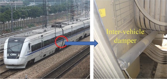
Inter-vehicle dampers, as shown in Fig. 1, are popularly used in modern high-speed trains [1-3] to attenuate relative motions of adjoining cars and improve passenger ride comfort. Longitudinally devised dampers are more appropriate for damping relative yaw and pitch motions of two cars, and the lateral dampers which are usually devised between car-body and coupler [2], and/or between two car-bodies are more appropriate for damping relative lateral shift, yaw and roll motions of two adjacent cars.
Fig. 1Aninter-vehicle hydraulic damper used in a Chinese CRH high-speed train. (Pictures taken by Wenlin Wang in Nanchang Railway Station on 19 May, 2019)
In previous works, many researchers have studied the effects of bogie primary and/or secondary suspension parameters [4] and parameter uncertainty [5] on vehicle system dynamics, the topic of multi-objective optimization of damper characteristics or overall suspension parameters [6, 7] using the genetic algorithms has also been well discussed. However, the research about inter-vehicle damper and its optimization problem seems inadequate, the influence of inter-vehicle damper parameters such as damping coefficient, attachment stiffness [8] and layout [9] on vehicle system dynamics has been preliminarily researched, in addition, Ma et al. [10] has studied the effectiveness of inter-vehicle damper on reducing wheelset lateral shift force and derailment coefficient of two high-speed trains passing each other.
Thus, research work studying the parameter sensitivity of inter-vehicle damper on vehicle system dynamics is inadequate, the problem of inter-vehicle damper optimization has hardly been addressed. As a matter of fact, as an example illustrated in Fig. 1, industry operating and maintenance of the CRH train reports that there exist problems about the design and vibration reduction effect of the inter-vehicle damper.
In this study, MBS modelling of a high-speed CRH train with inter-vehicle dampers is firstly carried out, vehicle system dynamics simulations including the lateral vibration, the ride comfort, the curving performance and the anti-shock performance of two trains passing each other are then performed by using the MBS model, the mechanism and quantification of inter-vehicle damper effect on the CRH train dynamics are finally analyzed. Thus, the MBS model developed and results obtained in this work would be useful for the next step inter-vehicle suspension optimization of the CRH train.
2. MBS modelling of a CRH train with inter-vehicle suspension
To study the effect of inter-vehicle damper and its parameters on the vibration reduction of a high-speed train, Multi-body System (MBS) modeling of the CRH train in SIMAPCK environment is carried out, and modelling the inter-vehicle damper has to be firstly addressed.
Fig. 2 shows the structural and damping mechanism of the inter-vehicle hydraulic damper, it illustrates that the damper is of shim stack type [4], which would produces damping forces by forcing oil through the shim stack valves devised in the pistion and/or the foot valve assemblies when the damper is excited by vehicle vibration.
Fig. 2Structural and damping mechanism of the inter-vehicle hydraulic damper. (Cross-section diagram of the damper product was permitted for publication by Zhuzhou Lince Group Shock Absorber Co., Ltd, Fig. 2 was produced and marked by Wenlin Wang in May, 2023)

A simplified-parametric model was proposed to depict damping characteristics of the inter-vehicle damper in MBS modelling, as:
where is damping force (N); is resultant vibration velocity along axis of the damper (m/s), and are respectively damping coefficients before and after saturation (Ns/m); is damper saturation speed (m/s).
The resultant vibration velocity in Eq. (1) can be formulated by:
where , and are respectively partial velocities along the -, - and -axises (m/s); , and are space coordinates depicting dynamic positions of the two mounting points of the damper (m). The proposed damper model was validated and calibrated by experimental results of the damper product, in addition, the characteristics of the rubber below buffer used in the inter-vehicle suspension is also obtained by bench test.
In MBS modelling of the CRH train, the Chinese LMA worn wheel profile and the CN 60 kg/m Chinese standard rail profile are used, while the simplified Kalker’s law is employed to calculate the creep forces. The American sixth grade track profiles (Am6) are used as track inputs, and the spectrum density function for the rail’s vertical and alignment profile is given by:
while that for the rail’s cross level and gauge profile is given by:
where is the spatial frequency in (rad/m) and is the spectrum density in (cm2/(rad/m)).
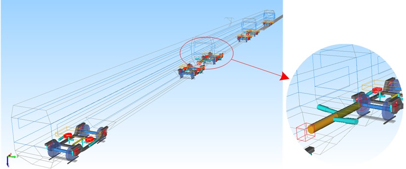
Simulation results agree well with actual test or running data of the CRH train, thus, the MBS model developed, as demonstrated in Fig. 3, is accurate and would be useful in the next step vibration analysis.
Fig. 3The developed MBS model of a CRH train with inter-vehicle suspension
3. Effect of inter-vehicle damper on CRH train dynamics
3.1. Lateral vibration
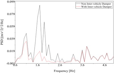
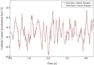
Fig. 4 comprehensively indicates the effect of inter-vehicle damper on lateral vibration of the CRH train. Fig. 4(a) shows that when with inter-vehicle damper lateral vibration acceleration of the middle car end has been obviously reduced, Fig. 4(b) also proves that the inter-vehicle damper can significantly attenuate the energies at main frequencies between 1-2 Hz.
Table 1 summarizes the effect of inter-vehicle damper on Root Mean Square (RMS) values of lateral vibrations of the CRH train, and demonstrate that when with inter-vehicle damper, RMS value of the lateral acceleration of the CRH train can be maximumly reduced by 32.5 %, while that of the yaw acceleration can be maximumly reduced by 30.1 %.
Fig. 4Effect of inter-vehicle damper on lateral vibration of the CRH train: a) Middle car end lateral acceleration and b) PSD

a)
b)
Table 1Effect of inter-vehicle damper on RMS values of lateral vibrations of the CRH train
Vehicle | RMS value of car end lateral acceleration (m/s2) | RMS value of car end yaw acceleration (rad/s2) | ||||
Non inter-vehicle damper | With inter-vehicle damper | Effect | Non inter-vehicle damper | With inter-vehicle damper | Effect | |
Head car | 0.450 | 0.335 | ↓25.6 % | 0.032 | 0.026 | ↓21.3 % |
Middle car | 0.445 | 0.300 | ↓32.5 % | 0.032 | 0.022 | ↓30.1 % |
Tail car | 0.469 | 0.368 | ↓21.5 % | 0.034 | 0.028 | ↓20.0 % |
3.2. Ride comfort
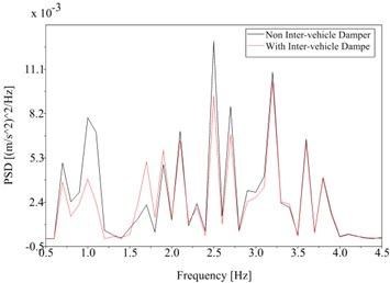
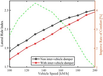
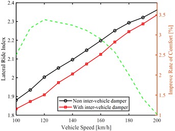
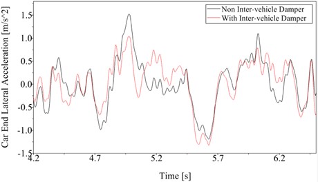
Fig. 5 comprehensively indicates the effect of inter-vehicle damper on ride comfort of the CRH train. Figs. 5(a) and (b) combine to show that when with inter-vehicle damper lateral acceleration and its energies at main frequencies between 0.5-4 Hz of the car-body have been obviously reduced, Figs. 5(c) and (d) also demonstrate that when with inter-vehicle damper, passenger ride comfort in the middle car can be maximumly improved by 4.38 %, while that in the tail car can be maximumly improved by 3.38 %.
3.3. Anti-shock performance of two trains passing each other
Fig. 6 indicates the effect of inter-vehicle damper on anti-shock performance of two CRH trains passing each other. Figs. 6(a) and (b) combine to show that when with inter-vehicle damper, both lateral vibration acceleration and especially roll acceleration at the end of the middle car have been greatly reduced.
Fig. 5Effect of inter-vehicle damper on ride comfort of the CRH train: a) Middle car-body lateral acceleration and b) PSD, c) Lateral ride indices and comfort improvement rates of the middle car and d) the tail car
a)
b)
c)
d)
Fig. 6Effect of inter-vehicle damper on anti-shock performance of two CRH trains passing each other: a) Profiles of the lateral acceleration and b) the roll acceleration at the end of the middle car
a)
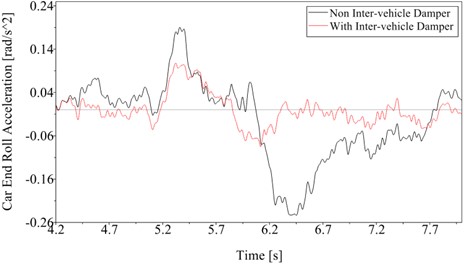
b)
From another point of view, Fig. 6(b) demonstrates that when with non inter-vehicle damper, the maximum roll acceleration of the compartment would be almost three times of that when with inter-vehicle damper, thus, not only can the inter-vehicle damper obviously reduce normal lateral vibrations, but also can it resist severe lateral shocks and guarantee safety when two trains pass each other.
4. Conclusions
1) A simplified-parametric model was proposed and validated to depict damping characteristics of the inter-vehicle damper in MBS modelling of the CRH train, followed research works and results show that the proposed damper model is accurate and useful.
2) Inter-vehicle damper devised in high-speed train can obviously reduce lateral vibrations at the connecting passage of adjacent compartments without increasing the wheelset lateral shift force and derailment coefficient, thus it can improve overall ride comfort of the CRH train. In addition, inter-vehicle damper can resist severe lateral shocks and guarantee safety when two high-speed trains pass each other.
3) The developed MBS model of the CRH train is an accurate and useful platform, the obtained results in this study are also valuable in following vibration analysis and inter-vehicle suspension optimization of the CRH train.
References
-
K. Tanifuji, K. Sakanoue, and S. Kikko, “Modelling of aerodynamic force acting on high speed train in tunnel and a measure to improve the riding comfort utilising restriction between cars,” Vehicle System Dynamics, Vol. 46, No. sup1, pp. 1065–1075, Sep. 2008, https://doi.org/10.1080/00423110802158747
-
D. Brabie and E. Andersson, “On minimizing derailment risks and consequences for passenger trains at higher speeds,” Proceedings of the Institution of Mechanical Engineers, Part F: Journal of Rail and Rapid Transit, Vol. 223, No. 6, pp. 543–566, Nov. 2009, https://doi.org/10.1243/09544097jrrt271
-
S. G. Zhang, Research on Design Approach for High-Speed Train (in Chinese). (in Chinese), China Railway Publishing House Co., Ltd.: Beijing, China, 2009.
-
W. L. Wang, Z. R. Zhou, D. S. Yu, Q. H. Qin, and S. Iwnicki, “Rail vehicle dynamic response to a nonlinear physical ‘in-service’ model of its secondary suspension hydraulic dampers,” Mechanical Systems and Signal Processing, Vol. 95, pp. 138–157, Oct. 2017, https://doi.org/10.1016/j.ymssp.2017.03.031
-
K. Zhou, T. You, D. Gong, and J. Zhou, “Effects of uncertain suspension parameters on dynamic responses of the railway vehicle system,” Probabilistic Engineering Mechanics, Vol. 71, p. 103405, Jan. 2023, https://doi.org/10.1016/j.probengmech.2022.103405
-
G. Li, R. Wu, X. Deng, L. Shen, and Y. Yao, “Suspension parameters matching of high-speed locomotive based on stability/comfort pareto optimization,” Vehicle System Dynamics, Vol. 60, No. 11, pp. 3848–3867, Nov. 2022, https://doi.org/10.1080/00423114.2021.1979602
-
X. Zhang, H. Li, J. Cheng, L. Sheng, and Y. Yao, “Adaptive stability mechanism of high-speed train employing parallel inerter yaw damper,” Vehicle System Dynamics, Vol. 61, No. 1, pp. 38–57, Jan. 2023, https://doi.org/10.1080/00423114.2022.2045027
-
C. Sun, “Research on influence of the characteristic parameter of inter-vehicle longitudinal damper on dynamic performance of high speed EMUs,” Journal of Mechanical Engineering, Vol. 53, No. 24, p. 170, 2017, https://doi.org/10.3901/jme.2017.24.170
-
Y. Z. Sun and B. L. Chen, “Research on best layout and dynamic behavior of inter-vehicle damper in CRH2 EMU,” Railway Locomotive and Car, Vol. 40, No. 4, pp. 64–71, 2020.
-
C. Ma, A. Zhu, F. Zhang, J. Yang, and P. Sun, “Effect of high-speed trains passing each other on wheel wear under different track excitations,” Proceedings of the Institution of Mechanical Engineers, Part F: Journal of Rail and Rapid Transit, Vol. 237, No. 4, pp. 470–478, Apr. 2023, https://doi.org/10.1177/09544097221118154
About this article

The authors thank fundings from the National Natural Science Foundation of China (NSFC) under Grant No. 12072075 and No. 11572123.
The datasets generated during and/or analyzed during the current study are available from the corresponding author on reasonable request.
The authors declare that they have no conflict of interest.
