Abstract
Multibody system (MBS) dynamics modelling and simulation of high-speed train system is essential and meaningful in the context of train dynamics research and product design. In this work, MBS modelling of a CRH high-speed train is carried out, in the modelling process, nonlinear geometry of wheel-rail contact, nonlinear characteristics of the suspensions and nonlinear railroad irregularities are fully considered. With the obtained MBS model, simulation is performed and demonstrates that critical speed of the CRH train is 378 km/h, vertical ride comfort of the CRH train is in “Excellent” level and lateral ride comfort is in “Good” level, in addition, RMS derailment coefficient of the train is less than 0.5 which means curving performance of the train is good. Agreement of simulation result with actual test or running data validates the established MBS model, thus, the MBS model developed in this study is accurate and would be useful in the next step vibration analysis and suspension optimization of the CRH train.
1. Introduction
With the rapid development of high-speed railway transportation in recent years, modern railway vehicle safety and ride comfort [1-2] becomes an essential subject in the context of vehicle system dynamics research, and Multibody System (MBS) dynamics modelling and simulation [3-4] are frequently used in the vehicle system vibration analysis and suspension optimization.
In previous works, Wang et al. [5] has studied a locomotive’s dynamic response to in-service parameter variations of its suspension damper by means of MBS modelling, Bideleh et al. [6] and Yao et al. [7] have performed sensitivity analysis of bogie dynamics to suspension parameters, in addition, Zhou et al. [8] has particularly studied the effects of suspension parameter uncertainties. Based on the above parameter sensitivity analysis, multi-objective optimizations of railway vehicle suspensions using design of experiment (DoE) approach [9] or genetic algorithms [10-11] have been carried out.
In this study, MBS modelling of a high-speed CRH train is carried out, vehicle system dynamics simulations including the nonlinear stability, the ride comfort and the curving performance are performed. Agreement of simulation result with actual running data validates the established MBS model, thus, the MBS model developed is useful and would act as a platform in the next step vibration analysis and suspension optimization of the CRH train.
2. Multi-body system dynamics modelling
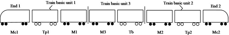
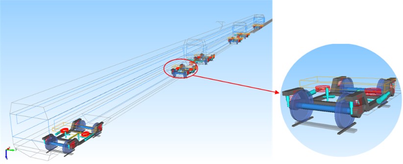
Fig. 1 shows the configuration of a Chinese CRH high-speed train which consists of two end units (Mc1, Mc2), three power units electric motors (M1, M2, M3), two trailer units with pantographs (Tp1, Tp2) and one pure trailer (Tb). The basic train unit 1includes Mc1, Tp1 and M1, the basic train unit 2 includes Mc2, Tp2 and M2, and the basic train unit 3 includes M3 and Tb. The eight cars are coupled together with couplers and draft gears, and with inter-car hydraulic dampers.
Fig. 1The configuration of a Chinese CRH high-speed train
2.1. Modelling the nonlinear components
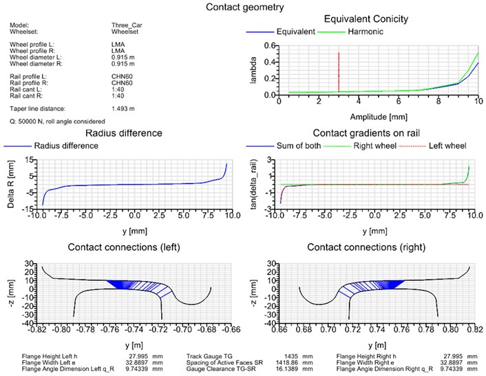
MBS modelling of the above CRH train is carried out in the SIMPACK software environment. In modelling nonlinear wheel-rail contact, the Chinese LMA worn wheel profile and the CN 60 kg/m Chinese standard rail profile are used, the simplified Kalker’s law is employed to calculate the creep force, thus, the obtained nonlinear geometry of wheel-rail contact is demonstrated by Fig. 2.
Fig. 2The nonlinear geometry of wheel-rail contact
The suspension system includes the primary suspension with coil spring and axle damper, the secondary suspension with air springs and vertical and lateral hydraulic dampers and the inter-car suspension with coupler and draft gear, and with inter-car hydraulic dampers.
In modelling the nonlinear railroad irregularities, the American fifth grade track profiles are used as track inputs, in which the vertical and alignment profile spectrums are respectively formulated by:
and:
the cross level and gauge profile spectrums are formulated by:
where the meaning, value and dimension of the parameter symbols in Eqs. (1-3) are documented in Table 2. Thus, the final nonlinear railroad irregularities in time domain are obtained and shown in Fig. 3.
Table 1The meaning, value and dimension of the parameter symbols in Eqs. (1-3)
Parameter | Symbol | Value | Dimension |
Roughness constant | 0.2095 | cm2/(rad/m) | |
0.0762 | |||
Cutoff frequency | 0.8209 | rad/m | |
0.8245 | |||
Coefficient | 0.25 | – | |
Power spectrum density | – | cm2/(rad/m) | |
Spatial frequency | – | rad/m |
Fig. 3The obtained nonlinear random a) vertical and b) lateral railroad irregularity profiles
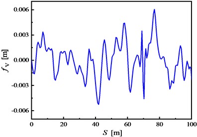
a)
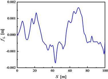
b)
2.2. The main dynamic indices
The ride comfort index for simulation of the high-speed train can be calculated by:
where is the car-body vibration acceleration (m/s2), is vibration frequency (Hz) and is coefficient for frequency correction. Thus, the class for ride comfort evaluation of the high-speed train calculated by Eq. (4) can be shown by Table 2.
In addition, the derailment coefficient for evaluating curving behavior of the high-speed train can be calculated by:
where is the wheel-rail lateral force (kN), is the wheel-rail vertical force (kN), is the angle of wheel flange (rad) and is the wheel-rail friction coefficient.
Table 2The ride comfort class of the high-speed CRH train
Class of ride comfort | Ride index | Meaning |
Class 1 | 2.50 | Excellent |
Class 2 | 2.50 2.75 | Good |
Class 3 | 2.75 3.00 | Ordinary |
2.3. MBS model of the high-speed train
The finally obtained MBS model of the CRH train is illustrated in Fig. 4, for simplicity, this model consists of three vehicles “Mc-Tp-M”. Followed nominal force calculation shows that the acceleration of the MBS model in its equilibrium state is 6.24E-10 m/s2, which is far less than the evaluation criteria of 1E-4 m/s2, indicating that the established MBS model is pretty accurate.
Fig. 4MBS model of the CRH high-speed train
3. Dynamics simulation
3.1. Nonlinear stability
Vehicle system dynamics of the CRH train are simulated by using the above MBS model. Fig. 5 demonstrates nonlinear stability characteristics of the train. As an example, Fig. 5(a) shows lateral excursion behavior of the No. 3 wheelset of the head carat different speeds, Fig. 5(a) illustrates that when vehicle speed equals to or exceeds 380 km/h, lateral vibration of the No. 3 wheelset diverges, thus, critical speed of the head car is 380 km/h.
Fig. 5(b) summarizes the wheelset lateral excursion limit cycles of the three vehicles. Fig. 5(b) indicates that when vehicle speed falls between 370-380 km/h, limit cycles of the three vehicles occur, thus, it can be concluded from the simulation that nonlinear critical speed of the CRH train is 378 km/h, which is consistent with the actual test result of the CRH train [12].
3.2. Ride comfort
Fig. 6 demonstrates riding performance of the CRH train. As an example, Fig. 6(a) shows lateral acceleration of the middle car-body at different speeds, it indicates that the accelerations fall within a scope of –0.5 m/s2~0.4 m/s2, which means good ride comfort.
Fig. 5Nonlinear stability characteristics of the CRH train: a) lateral excursion of the No. 3 wheelset of the head car, b) wheelset lateral excursion limit cycles of the three vehicles
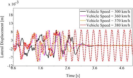
a)
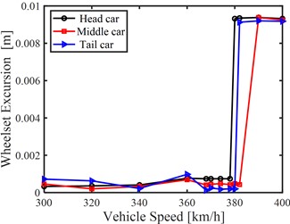
b)
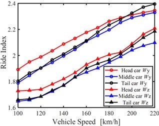
Fig. 6(b) concretely summarizes the vertical and lateral ride comfort indices of the three vehicles, referring to Table 2, vertical ride comfort of the CRH train is in “Excellent” level, while lateral ride comfort of the CRH train is in “Good” level. The simulated ride comfort results also agree well with actual test result of the CRH train [12].
Fig. 6Riding performance of the CRH train: a) lateral acceleration of the middle car-body, b) vertical and lateral ride comfort indices of the three vehicles
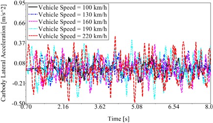
a)
b)
3.3. Curve negotiation performance
Fig. 7 demonstrates curving behavior of the CRH train.
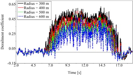
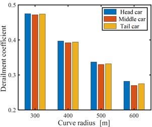
Fig. 7Curving behavior of the CRH train: a) derailment coefficient profile of the middle car, b) a summary of RMS derailment coefficients of the three vehicles
a)
b)
Fig. 7(a) shows derailment coefficient profiles of the middle car when it is passing through different curves at a constant speed of 80 km/h, Fig. 7(a) indicates that the maximum derailment coefficient is less than 0.6 when the train is negotiating a tight curve with 300 m radius.
In addition, Fig. 7(b) summarizes the RMS derailment coefficients of the three vehicles, Fig. 7(b) indicates that curving performance of CRH train is good. The simulated derailment coefficient level is also consistent with the actual test result and field curving performance of the CRH train [12].
4. Conclusions
1) In MBS modelling of the CRH high-speed train, nonlinear geometry of wheel-rail contact, nonlinear characteristics of the suspensions and nonlinear railroad irregularities are fully considered, thus, this will improve and benefit the accuracy of MBS model and simulation results.
2) Simulation results indicate that critical speed of the CRH train is 378 km/h, vertical ride comfort of the CRH train is in “Excellent” level and lateral ride comfort is in “Good” level, in addition, RMS derailment coefficient of the train is less than 0.5 which means curving performance of the train is good.
3) Simulation results agree well with actual test or running data of the CRH train, thus, the MBS model developed in this study is accurate and would be useful in the next step vibration analysis and suspension optimization of the CRH train.
References
-
W. H. Zhang, “The development of China’s high-speed railway systems and a study of the dynamics of coupled systems in high-speed trains,” Proceedings of the Institution of Mechanical Engineers, Part F: Journal of Rail and Rapid Transit, Vol. 228, No. 4, pp. 367–377, May 2014, https://doi.org/10.1177/0954409713478528
-
X. Liang, T. Jiang, Y. Hong, J. Zhang, M. Jiang, and Z. Wang, “Vibration response analysis of simply supported box girder bridge-maglev train in accelerated test of Changsha maglev express,” Advances in Materials Science and Engineering, Vol. 2020, pp. 1–18, Nov. 2020, https://doi.org/10.1155/2020/9563747
-
A. Ibrahim, M. A. Abdullah, and K. Hudha, “Multibody dynamics models of railway vehicle using Adams/Rail,” Applied Mechanics and Materials, Vol. 393, pp. 644–648, Sep. 2013, https://doi.org/10.4028/www.scientific.net/amm.393.644
-
F. Liu, F. Gu, A. D. Ball, Y. Zhao, and B. Peng, “The validation of an ACS-SSI based online condition monitoring for railway vehicle suspension systems using a SIMPACK model,” in 2017 23rd International Conference on Automation and Computing (ICAC), pp. 1–6, Sep. 2017, https://doi.org/10.23919/iconac.2017.8082030
-
W. L. Wang, D. S. Yu, Y. Huang, Z. Zhou, and R. Xu, “A locomotive’s dynamic response to in-service parameter variations of its hydraulic yaw damper,” Nonlinear Dynamics, Vol. 77, No. 4, pp. 1485–1502, Sep. 2014, https://doi.org/10.1007/s11071-014-1393-2
-
S. M. Mousavi Bideleh and V. Berbyuk, “Global sensitivity analysis of bogie dynamics with respect to suspension components,” Multibody System Dynamics, Vol. 37, No. 2, pp. 145–174, Jun. 2016, https://doi.org/10.1007/s11044-015-9497-0
-
Y. Yao, X. Chen, H. Li, and G. Li, “Suspension parameters design for robust and adaptive lateral stability of high-speed train,” Vehicle System Dynamics, Vol. 61, No. 4, pp. 943–967, Apr. 2023, https://doi.org/10.1080/00423114.2022.2062012
-
K. Zhou, T. You, D. Gong, and J. Zhou, “Effects of uncertain suspension parameters on dynamic responses of the railway vehicle system,” Probabilistic Engineering Mechanics, Vol. 71, p. 103405, Jan. 2023, https://doi.org/10.1016/j.probengmech.2022.103405
-
D. S. Y. A. W. L. Wang and S. Iwnicki, “Nonlinear optimal specification of a locomotive axle-box hydraulic damper for vibration reduction and track-friendliness,” The Dynamics of Vehicles on Roads and Tracks, pp. 1457–1466, Mar. 2016, https://doi.org/10.1201/b21185-154
-
G. Li, R. Wu, X. Deng, L. Shen, and Y. Yao, “Suspension parameters matching of high-speed locomotive based on stability/comfort pareto optimization,” Vehicle System Dynamics, Vol. 60, No. 11, pp. 3848–3867, Nov. 2022, https://doi.org/10.1080/00423114.2021.1979602
-
X. Zhang, H. Li, J. Cheng, L. Sheng, and Y. Yao, “Adaptive stability mechanism of high-speed train employing parallel inerter yaw damper,” Vehicle System Dynamics, Vol. 61, No. 1, pp. 38–57, Jan. 2023, https://doi.org/10.1080/00423114.2022.2045027
-
B. M. Wang, System and Bogie of High-speed EMUs. (in Chinese), Chengdu, P.R. China: Southwest Jiaotong University Press, 2008.
About this article

The authors thank fundings from the National Natural Science Foundation of China (NSFC) under Grant No. 12072075 and No. 11572123.
The datasets generated during and/or analyzed during the current study are available from the corresponding author on reasonable request.
The authors declare that they have no conflict of interest.
