Abstract
The paper presents tools for vibration evaluation of power train mounting system of a passenger car to meet demands for passenger’s comfort. The computational model is based on the Multi-Body System principles and includes submodules as are engine, clutch, gearbox, final drive, drive shafts and rheological models of all power train mountings. Simulation results are validated on account of measurement of power train vibration at different engine load conditions. Both simulation and measurement are carried out at power train of the European B-segment car with an in-line three-cylinder spark-ignition engine and manual gearbox. Presented methodology can bring time and cost savings particularly during mountings design process.
1. Introduction
An internal-combustion engine is one of the main sources of vibration transmitted to the vehicle body as a result of engine’s working principle. Without a good isolation, accompanying dynamic disturbances could cause a rapid fatigue of vehicle components and a huge discomfort for the passengers and this is the reason why the power train mounts (engine mount, gearbox mount and torque rod) have to be an integral and essential part of power train development.
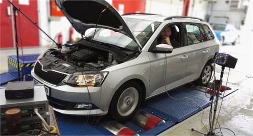
In spite of long history of the mounting systems development, need for further improvement in the performance of engine mounting systems for new modern small cars still exists [1]. These cars, Fig. 1, have lightweight power train with small engine, lightweight car body and low idle speed. However, these trends can cause low-frequency vibration of the car body, lowering ride comfort and acting on passengers.
Fig. 1Measurement of vibration at full engine load
As the response to this challenge, traditional physical prototyping and testing (highly time-consuming and expensive processes) are gradually being replaced by virtual prototyping and simulations, including components from rubber-like materials. However, this way of development has been more or less overlook in this case of rubber components, partially due to problematic modelling of complex characteristics of rubber, but also due to limited understanding of the mechanical properties of rubber-like materials [2]. This article therefore presents potential in inclusion of rubber-like components into power train unit simulations.
2. Computational model
Analytical models are not sufficient for complete description of dynamic behaviour of specific components and therefore more complex numerical model based on Multi-Body SW are usually used [2].
The multibody method utilizes rigid and flexible bodies, joints, springs, dampers, and actuators to represent a physical system. The movement of bodies is described by ordinary differential equations (ODE) which are based on the fundamental equations of motion. Mechanical joints between bodies are represented by non-linear algebraic equations [3].
The MBS computational model can incorporate rigid and flexible bodies. At rigid bodies, the mass and inertia properties are invariable in time and the body is unable to deform with loading. Two arbitrary points on a rigid body cannot move against each other [4].
The used MBS model of power train, Fig. 2, just consist in rigid bodies, because there is no intention to calculate stress of individual components, but only excitation effect in mounts caused by their inertia properties [5]. Another specificity of the model is simulation of torque transmission from crankshaft up to wheels allowing a good understanding of the difference between engine idling and full load.
Fig. 2Computational model of a vehicle power train
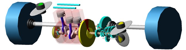
The vibration and force excitations caused by crank train originate from gas pressure and firing order, unbalances and operating conditions, such as engine load and speed. The conception of crank train substantially affects frequency spectrum of the power train vibration. Expected harmonic orders of described crank train without balancing shaft are therefore 1st, 1.5th, 2nd, 3th, 4.5th and 6th.
The term power train includes all driven components from crankshaft pulley to vehicle wheels. These are crank train, complete clutch, gearbox, final drive, drive shafts and wheels. Many of these components are included as a lumped parameter model, because modally reduced FE bodies are not necessary for analysis like this, however FEM is used for determination of some of these parameters.
3. Power train mounts
The primary function of mounts is to support weight of the power train and to reduce the transmission of power train vibration to the car body. The design of the engine mount system thus has to meet static and dynamic load requirements.
To isolate vibration caused by the crank train unbalance and reaction torque, i.e. in order to ensure low values of vibration transmissibility, low elastic stiffness and damping are needed as the forces transmitted to the structure of the car body are related to the stiffness and damping of the mounts [6].
However, if the mount’s elastic stiffness and damping are too low, the transient response of the power train mount system can become problematic in the case of shock excitations caused, for example, by sudden vehicle and engine acceleration and deceleration, braking and riding on uneven roads. Hence, from this point of view, high elastic stiffness and damping are required to minimize the engine motion and to absorb power train shake. The final design of the power train mounts has to be a compromise between these requirements. This is the reason why more basic concepts of mounts were developed: for example, elastomeric mounts or hydraulic mounts.
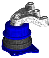
Simple elastomeric mounts offer advantages in the view of their compactness, low costs and undemanding maintenance. The dynamic stiffness of an elastomeric mount at higher frequencies is generally higher than its stiffness at lower frequencies [7]. In tested car, rubber mount is used as the gearbox mount and the torque rod.
A range of hydraulic mounts have been developed to realize enhanced variable damping properties. Such mounts are tuned to achieve high damping near the power train bounce frequency for resonance control and relatively low stiffness under high frequency excitation [7]. In the case of the mentioned car, hydro mount is used as the engine mount, Fig. 3.
Fig. 3FE models of mounts: a) engine, b) gearbox, c) torque rod
a)
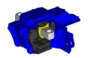
b)

c)
3.1. Mounts static properties
Rubbers are hyperelastic and viscoelastic materials whose mechanical properties are strain-rate and time dependent. The properties of rubber when subjected to a steady state or a slowly applied load are referred to as static properties, whereas the properties of rubber when subjected to a dynamic load are referred to as dynamic properties.
The important static properties of rubber are related to strength and hardness [8]. They are typically measured to check if the rubber is being produced to required standard or specification. Some common static properties of rubber are hardness, elongation-to-tear, bulk modulus, tensile strength, tensile modulus, shear modulus and toughness [9].
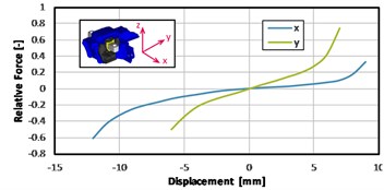
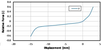
In the Fig. 4 it can be seen an example of the force-displacement relation of one of the measured mounts (gearbox mount) in three axes. In the case of this mount, the static stiffness is very direction dependent.
Fig. 4Measured results of a gearbox mount static stiffness
a)
b)
3.2. Mounts dynamic properties
The dynamic properties of rubber (i.e., shear modulus, shear stiffness) are generally obtained from the response of a specimen to harmonic deformation [10].
Viscoelasticity refers to the combination of elastic (solid like storage of elastic energy) and viscous (liquid like dissipation of energy) features of the behaviour:
where is storage modulus (representing energy stored elastically), is loss modulus (representing loss energy during deformation), is complex dynamic modulus and is loss angle [10, 11].
To perform dynamic analysis of structures with elastomers (such as vibration dampers – mounts), the description of the rheological behaviour of the elastomer has to be done. The rheological behaviour is usually represented with a stress-strain plot and may be frequency, temperature, and strain (amplitude) dependent.
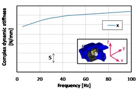
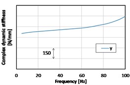
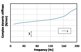
In the Fig. 5, the measured dynamic stiffness can be seen (gearbox mount). This complex dynamic stiffness is the expression of stiffness in a complex form and its real part is called storage modulus and imaginary part is called loss modulus. Both the real and imaginary parts are frequency, temperature and displacement-magnitude dependent. The ratio between storage and loss modulus is called loss factor:
Fig. 5Measured results of a gearbox mount dynamic stiffness (complex stiffness amplitude)
a)
b)
c)
3.3. Computational model of mounts
The dynamic behaviour of viscoelastic materials is often simulated by a set of springs and viscous dampers connected in variety of configurations [12]. The simplest type of configuration represents Maxwell model (linear spring in series with linear damper) and Kelvin-Voigt model (linear spring and linear damper placed in parallel) [13, 14].
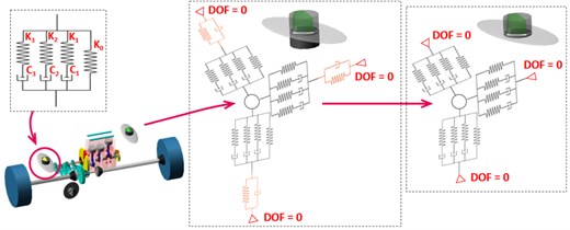
The most often model used to simulate the dynamic response of viscoelastic material is generalized Maxwell model, also known as a Prony series. The model is assembled from n Maxwell models in parallel with a spring (if only one Maxwell is in parallel with the spring, the model is called Poynting-Thomson. It can be found a Prony series named as extended Poynting-Thomson model [8]). The number of required Maxwell models used in parallel depends on the shape of measured stiffness-frequency curve which is used for fitting. For the purpose of our Multi-Body model, there are used three Prony series terms (total three dampers and four springs, see Fig. 6.) [7].
The car body stiffness can also be incorporated into the Multi-Body model. In principle, two approaches are possible [7]. First one is more realistic and theoretically more correct, however it is more difficult to obtain input data. In this case, car body is completely simulated with its stiffness and damping properties, which has to be measured. The second approach simplifies model by set up a car body as a rigid body, so vibration of car body is equal to zero. If measured vibration the side of the car body are subtracted from vibration at the side of the power train, this approach, Fig. 6, can be compared with measurement.
Fig. 6Computational model of mounts for simulation in MBS
4. Experimental validation of simulation
For verification of calculated results from Multi-Body simulation, an extensive set of measurements is carried out. The measurement is performed with 200 rpm speed step and statistical repeatability of measurement is reached by sufficient number of repeats in each speed point. Each mount is equipped by two 3-axis accelerometers: one at the power train side and one at the car body side near the mount.
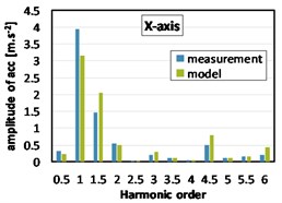
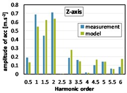
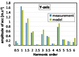
During the measurement without load, the vehicle stands on a flat floor, wheels are not rotating, a gear lever is moved to neutral position and engine speed is setup by software for control of engine control unit. Measured data and data from simulation both shows a significant amplitude of 1st harmonic order, which was expected. The differences between results from model and measured data are not greater than 16 %, see Fig. 7.
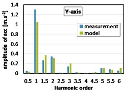
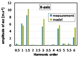
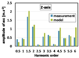
During the measurement with full load, the vehicle dynamometer is used to measure this full load state (full throttle, third gear). As was expected, 1.5th, 3th, 4.5th etc. orders are more dominant with engine under full load, see Fig. 8. Greater values of harmonic components amplitudes obtained by simulation are caused due to variations in the inertia tensor of power train, further connections of the real power train with the car body (exhaust system) etc.
Fig. 7Harmonic analyses of acceleration at the gearbox mount (2000 rpm, without load)
a)
b)
c)
Fig. 8Harmonic analyses of acceleration at the gearbox mount (2000 rpm, full load)
a)
b)
c)
5. Conclusions
The design process of power train mounting system and its optimisation has to meet wide range of requirements which are often contradictory and except partial tuning and optimisation (frequency and temperature dependent stiffness, loss factor etc.), layout analysis of the mounting system must be done (mount locations and orientation angles of the individual engine rubber mounts).
Described computation model of power train vibration can help to understand the mechanism of power train vibration transmission to the car body and it is also helpful and suitable for parametric studies in early phase of power train design process.
References
-
Roderic L. Viscoelastic Materials. Cambridge University Press, New York, 2009, p. 461.
-
Williams H., Whear R. Elastomer model for virtual mounting models. SAE World Congress, Detroit, 2005, p. 111-114.
-
Prokop A., Řehák K. Virtual prototype application to heavy-duty vehicle gearbox concept. Engineering Mechanics, Svratka, Czech Republic, 2017, p. 810-813.
-
Ambrosio J., Gongalves J. Complex Multibody Systems with Application to Vehicle Dynamics. Kluwer Academic Publishers, Detroit, 2001, p. 216.
-
Drápal L., Šopík L. Influence of Crankshaft Counterweights upon Engine Block Load. Proceedings of International Conference Transport Means, Kaunas, Lithuania, 2016, p. 809-814.
-
Vahdati N., Saunders L. High frequency testing of rubber mounts. ISA Transactions, Vol. 41, Issue 2, 2002, p. 145-154.
-
Kim J., Kim H. Shape design of engine mount by method of parameter optimization. Computers and Structures, Vol. 65, 1997, p. 725-731.
-
Renardy M., Hrusa W., Nohel W. J. Mathematical Problems in Viscoelasticity. John Wiley, New York, 1987, p. 421.
-
Ward L. M, Hadley D. W. Mechanical Properties of Solid Polymers. John Wiley, New York, 1993, p. 232.
-
Sim S., Kim K. J. A method to determine the complex modulus and Poisson’s ratio of viscoelastic materials from FEM applications. Journal of Sound and Vibration, Vol. 141, 1990, p. 71-82.
-
He S., Singh R. Prediction of high frequency response characteristics of mounts. Proceedings of SAE Noise and Vibration Conference and Exhibition, 2005, p. 16-19.
-
Píštěk V., Klimeš L., Mauder T., Kučera P. Optimal design of structure in rheological models: an automotive application to dampers with high viscosity silicone fluids. Journal of Vibroengineering, Vol. 19, Issue 6, 2017, p. 4459-4470.
-
Wineman A., Rajagopal K. R. Mechanical Response of Polymers. Cambridge University Press, Cambridge, 2000, p. 296.
-
Brinson H., Brinson L. Polymer Engineering Science and Viscoelasticity. Springer, New York, 2015, p. 482.
About this article

The research leading to these results has received funding from the MEYS under National Sustainability Programme I (Project LO1202) and Specific Research Project of the Faculty of Mechanical Engineering, Brno University of Technology (FSI-S-17-4104).
