Abstract
This article presents the potential of computational modelling during the development of an unconventional crank train. The computational model is assembled as well as numerically solved in a Multi-Body System incorporating the modally reduced bodies and hydrodynamic bearings. Regarding the simulation results, the attention is paid to the torsional vibration and its analysis, including concept design of a torsional damper.
1. Introduction
Torsional vibration is common to internal-combustion engine crankshafts. The crank train generates alternating torque due to alternating combustion pressure in conjunction with the alternating effect of reciprocating parts inertia. This torque brings the elastic crankshaft in vibration about the axis of rotation. The torsional vibration can cause cracking and crankshaft failure; and therefore, this crankshaft loading is very dangerous.
This type of loading is investigated in the case of unconventional crank train of a 1.6-litre naturally aspirated spark-ignition in-line four-cylinder engine with reduced friction losses. The reducing of crank train friction losses is achieved by a reduced number of crankshaft main bearings from 5 to 3.
The new 3-main-bearing crankshaft is based on a 5-main-bearing version of the standard engine. The missing main bearings are replaced by sheet-metal webs due to mass and inertia moments reduction, see Fig. 1. A connection between the web and the crankshaft is created by laser welding for low thermal load of the weld. Current version of the 3-main-bearing crankshaft results from a previous design, computational, and technology studies [1].
Fig. 1An exploded view of the 3-main-bearing crankshaft
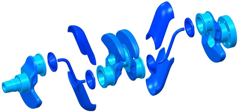
These studies show that potential for savings of power losses of crankshaft main bearing reaches around 33 % in comparison with the standard 5-main-bearing crankshaft.
However, not only friction losses are affected by the new crankshaft design, but also changes in system dynamic response must be taken into account. In order to investigate a dynamic response of excited crank train, the state-of-the-art computational approaches are used.
2. Simulations of crank train dynamics
A complex computational model of an engine (in other words a virtual engine) is solved in the time domain. This enables different physical problems including various non-linearities to be incorporated. The virtual engine is assembled as well as numerically solved in MBS (Multi-Body System) ADAMS which is a general code and enables integration of user-defined models to be made directly using ADAMS commands or user-written FORTRAN or C++ subroutines [2].
In general, the virtual engine includes all significant components necessary for dynamics analyses. The included module is a crank train, a valve train, a timing drive and a rubber damper. Following analyses just deal with the crank train as a main module of the virtual engine.
The crank train module consists of solid model bodies, linearly elastic model bodies and constraints between them. Solid model bodies – defined by location of centre of gravity, mass, and inertia tensor – are piston assembly, connecting rod assembly, dynamometer rotor. The linearly elastic model bodies are modally reduced finite element models suitable for dynamic simulation. These are crankshaft, crankshaft pulley, flywheel, engine block, cylinder head, crank train sump, gear case.
A dumb-bell shaft connecting a flywheel with a dynamometer rotor is represented by a body with defined torsional stiffness and damping. These characteristics are adjusted on account of torsional vibration measurement.
The interaction between the crankshaft and the engine block is ensured via a non-linear hydrodynamic journal bearing model [3].
Virtual engine is excited by means of cylinder pressure, defined by high-pressure measurement, and via inertial forces from moving parts. Simulations start from 1000 rpm and are carried out to 6200 rpm.
3. Torsional vibration
The crankshaft pulley angular displacement is chosen for description and comparison of the crank train torsional vibration due to its complexity, the crank train speed oscillation and crankshaft torsional static and alternating deformation are therefore included into this quantity.
Harmonic analysis of a pulley angular displacement of the standard crankshaft is shown in Fig. 2.
It is obvious that there is a relatively strong impact of the 6th harmonic component of the torsional vibration that is reaching resonance under the high speed. At 3900 rpm the resonance of the 8th harmonic component is evident. The 10th harmonic component shows some resonance too, but its impact on the total shaft oscillation is considerably smaller. The mentioned harmonic components bring crankshaft on alternating torsional deformation while lower harmonic components, reflecting resonances at lower engine speed (the 2nd one or the 4th one), show whole crank train speed oscillation.
Harmonic analysis of the torsional vibration proved the theoretical assumptions, namely the fact that the major orders take the highest part in vibrations due to their identical phase angle at all cylinder units of the engine. For the given engine concept these orders are integer multiples of 2. The synthesis is equal to the half-size of peak-to-peak value from the periodic torsional oscillation.
The occurrence of half-harmonic components (6.5th, 7.5th etc.) is caused by the fact that whole working cycle of a four-stroke internal-combustion engine takes two crankshaft revolutions (720°) while the fundamental frequency for engine dynamics is crankshaft rotational frequency (360°).
In the Fig. 3, the results of the new crank train harmonic analysis are presented. The virtual engine simulation has proved that the 3-main-bearing crankshaft is torsionally softer than the standard one. Lower torsional stiffness is evident, for example, at the resonance from the 8th harmonic component which occurs at 3600 rpm (minus 300 rpm in comparison with the standard one). This is caused mainly by enlarged counterweighs of the new crankshaft significantly reducing load of the middle main bearing however also decreasing torsional natural frequency of the crank train.
Fig. 2Harmonic analysis of a pulley angular displacement of the standard crankshaft
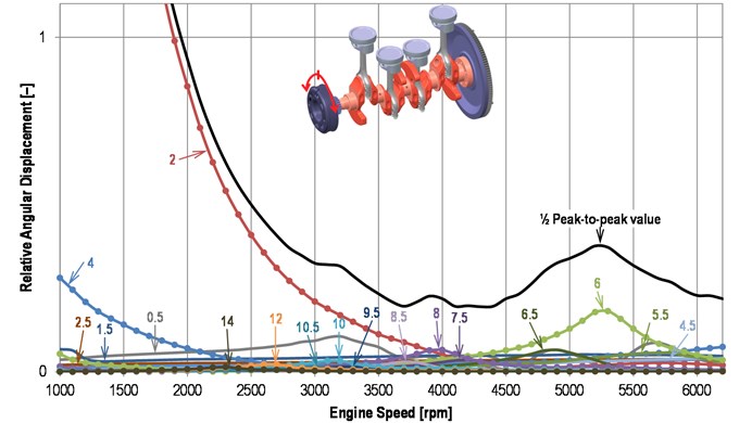
Fig. 3Harmonic analysis of a pulley angular displacement of the new crankshaft
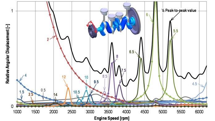
Nevertheless, the small number of the crankshaft pivot points at the engine block brings specific changes in crank train dynamics behaviour. The resonance amplitudes not only of the major harmonic orders but also the other harmonic orders are increased.
Crankshaft material has inherent damping determined by the experimental modal analysis for the need of simulation. However, as the simulation results show, “the sharpness” of resonance curves is caused, in particular, by the lower external damping of crank train torsional vibration since the dominant sources of damping are the crankshaft main bearings.
Shown torsional vibration of the new crankshaft, Fig. 3, cannot be admitted owing to likely crankshaft failure. Hence the next step for its reduction must be done.
4. Concept design of a torsional vibration damper
Engines of class as presented used to be equipped by a tuned rubber torsional vibration damper featured by good effect and low-costs. The damper consists of a rubber band interposed between an inertia ring and a crankshaft pulley and its function, in sum, rests in retuning of the torsional system and putting more damping into it.
4.1. Parameters of a torsional vibration damper
According to Fig. 4, that describes torsional system including the reduced crank train and parallel model of torsional damper and with the use of relative parameters, can be derived:
where is relative amplitude is relative damping relative frequency is the damper relative tuning and is relative size.
Fig. 4A scheme of reduced crank train with a torsional damper
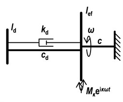
This formula allows to investigate the influence of damper relative parameters on the resonance curves of harmonic components of the crank train torsional vibration and is very useful for parametric studies.
Fig. 5Comparison of the torsional damper effect on resonance curve
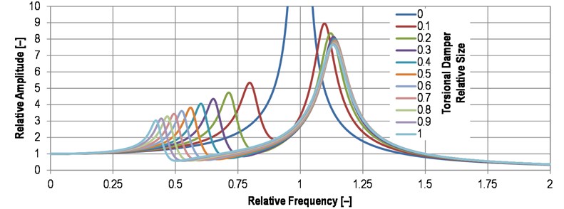
Resonance curves, presented in Fig. 5, show the influence of damper relative size on relative amplitude for given relative tuning and the same damping ratio. The range of damper parameters is, in practice, limited by the build-up area, and material properties of a rubber band.
4.2. Effect of a torsional vibration damper
The effect of the torsional vibration damper is verified by the virtual engine as well. Since real rubbers show hysteretic damping properties rather than viscous, Wiechert rheological model of a rubber band is used [11].
Fig. 6Comparison of the torsional damper effect on a crankshaft pulley angular displacement (½ peak-to-peak value)
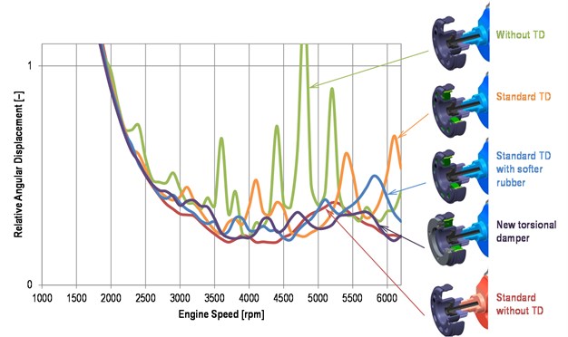
The influence of the torsional vibration damper upon a crankshaft pulley torsional vibration is shown in Fig. 6 where the notes used mean:
• Without TD: the new crank train without the torsional damper,
• Standard TD: the new crank train with torsional damper intended for the standard crank train,
• Standard TD with softer rubber: the new crank train with torsional damper intended for the standard crank train but with lower torsional stiffness of the rubber band,
• New torsional damper: the new crank train equipped with torsional damper with optimized parameters,
• Standard without TD: the standard crank train without a torsional damper.
Since the standard crank train can operate reliably without the use of a torsional damper (verified by a measurement), it is evident that the new crank train equipped by the optimized torsional damper should operate as well.
5. Conclusions
Modern internal-combustion engines have to meet strict requirements on fuel efficiency which can be reached, among others, by low friction losses of a crank train. However, lowering of friction losses is often attached to the decline in system dynamic behaviour. The described unconventional crank train represents an extreme case of this behaviour. Nevertheless, modern computational methods can bring solutions of the mentioned challenges and can shift manufacturing of expensive prototypes to later phase of the development process.
Further steps of this project will therefore be: a detail design of a torsional damper focused on temperature endurance of the rubber band, an analysis of crankshaft fatigue life, and a measurement of the real crank train prototype.
References
-
Drápal L., Novotný P., Maršálek O., Raffai P., Píštěk V. A Conceptual Study of Cranktrain with Low Friction Losses. MECCA – Journal of Middle European Construction and Design of Cars, Vol. 11, Issue 2, 2013, p. 6-11.
-
Novotný P. Virtual Engine – A Tool for Powertrain Development. Inaugural Dissertation, Brno University of Technology, Czech Republic, 2009.
-
Butenschön H. J. Das Hydrodynamische, Zylindrische Gleitlager Endlicher Breite Unter Instationärer Belastung. Ph.D. Dissertation, Universität Karlsruhe, Germany, 1976, p. 219.
-
Novotný P., Píštěk V. New efficient methods for powertrain vibration analysis. Proceedings of the Institution of Mechanical Engineers, Part D, Journal of Automobile Engineering, Vol. 224, Issue 5, 2010, p. 611-629.
-
Craig R. R. Structural Dynamics. John Willey and Sons, 1981, p. 527.
-
Nestorides E. J. A Handbook on Torsional Vibration. Cambridge University Press, Cambridge, 1958, p. 664.
-
Rebbert M. Simulation der Kurbewellendynamik unter Berücksichtigung der Hydrodynamischen Lagerung zur Lösung Motorakusticher Fragen. Ph. D. Dissertation, Rheinisch-Westfälischen Technischen Hochschule, Aachen, Germany, 2000, p. 110.
-
Hafner K. E., Maass H. Torsionsschingungen in der Verbrennungs-Kraftmaschine. Springer-Verlag, Vienna – New York, 1985, p. 434.
-
Heisler H. Advanced Engine Technology. 1st Edition. Arnold, Oxford, Great Britain, 2002, p. 794.
-
ADAMS/Engine Help. Version MD Adams R3. MSC.SOFTWARE, MSC Software Corporation, Newport Beach, CA, 2008.
-
Brinson H. F., Brinson L. C. Polymer Engineering Science and Viscoelasticity: An Introduction. Second Edition. Springer, New York, 2015, p. 482.
About this article

The research leading to these results has received funding from the MEYS under National Sustainability Programme I (Project LO1202) and Specific Research Project of the Faculty of Mechanical Engineering, Brno University of Technology (FSI-S-14-2334).
