Abstract
The influence of the geometrical and material parameters of damping coatings, covering helical spring wires, on the resonant longitudinal vibration amplitudes is presented in the paper. It is shown that coatings with geometrical parameters that are possible to obtain in practice allow the efficient reduction of the maximal amplitudes of these vibrations, when the materials used for coatings have properties specific for macromolecular polymers. The considerations are illustrated with numerical examples.
1. Introduction
Helical springs applied in general machine constructions are usually subjected to excitation, which consists of a static load component and a dynamic periodical load component. The static load component is mostly caused by a supported machine part weight or pre-tension, whereas the changing load component is a result of working machine excitations, foundation vibrations or both of these factors simultaneously. The natural frequencies of helical springs can be situated within the range of frequencies of the excitations mentioned above, both in steady and transient conditions, which may result in the generation of resonant spring vibrations, which are dangerous and detrimental from the spring durability point of view. The vast range of helical spring applications means that these vibrations constitute an important practical problem. Spring vibrations are a serious problem, among others, in vehicle suspension systems, fuel injection systems and timing systems in piston combustion engines [1]. Research focused on the reduction of combustion engine valve spring vibrations, which has been conducted for many years, indicates the importance of this problem [2-4]. There are many constructional solutions which aim to restrain this phenomenon [5-7]. The application of a damping coating covering the spring wire is one of methods that restrain the amplitudes of spring vibrations. This solution utilizes the internal material friction and, as opposed to the methods utilizing constructional friction, it also protects the spring wire against corrosion, which is a very important factor that negatively influences the fatigue strength of steel springs.
2. Longitudinal vibrations
In typical industrial applications of helical springs, like vibrating machine support or vibration isolation systems, one end of the spring is mounted to an element that can be treated as a fixed one, whilst the second end of the spring is subjected to vibrations, having an axial component of a certain amplitude and circular frequency . In conditions of steady resonant vibrations, the maximal spring vibration amplitude (a lower index denotes the number of the mode of longitudinal natural vibrations) can achieve such high values that it can be assumed with high accuracy that the mode of the spring vibrations corresponds to the mode characteristic for clamped-clamped boundary conditions.
2.1. Equivalent rod model
The equivalent rod model with suitable dynamic parameters can be utilised when considering the longitudinal vibrations of coated helical springs. The effects connected with damping can be initially omitted, as damping does not affect the normal mode shapes, and due to the relatively low damping obtained by elastomeric coatings, its influence on natural frequencies is small. Thus, the wave equation of undamped longitudinal vibrations of equivalent rod takes a conventional for :
where denotes the linear density of equivalent rod, whereas denotes an equivalent compression rigidity [8]:
where: – number of active coils, – current active spring height, – half of the nominal diameter of the spring, and – shear modulus of the spring wire and coating material respectively, and are area moments of inertia of the wire and coating cross-sections respectively.
2.2. Amplitudes of resonant longitudinal spring vibrations
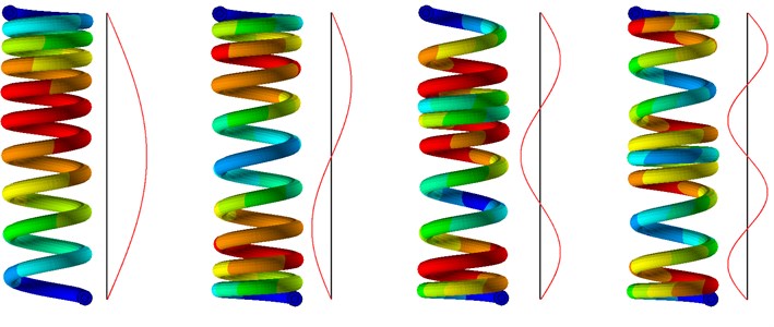
The first four normal longitudinal modes of a clamped-clamped coated helical spring as well as plots of the displacement amplitudes of equivalent rod modelling for the spring are presented in Fig. 1.
Fig. 1The first four longitudinal natural modes of a clamped-clamped coated helical spring with corresponding plots of displacement amplitudes of equivalent rod
Under the initial assumption that both ends of the spring are fixed, one can write the stationary solution of Eq. (1) and the time independent factor of this solution, which describes the amplitudes of longitudinal vibrations of equivalent rod modelling for the considered spring:
where 1, 2, 3,... denotes the number of the natural longitudinal frequency .
Knowing the shape of the vibration mode, one can calculate the maximal elastic energy stored in the spring in resonance conditions as a function of the maximal amplitude and, subsequently using the definition of the specific damping capacity , the energy dissipated during one period of vibrations can be determined. According to this definition [9], energy dissipated during the cycle is equal to the maximal potential energy of the vibratory system within one cycle multiplied by the specific damping capacity. In the case of a spring with a damping coating on its wire, the equivalent relative energy dissipation can be written in the form [10]:
where: is the specific damping capacity of the spring wire material, whereas is the specific damping capacity of the coating material. Longitudinal deformations of the spring are connected mainly with the twisting of the wire and the coating, thus the energy dissipated by the spring during one period of vibrations amounts to:
where: is the active length of the coating and the spring wire, – the coordinate along the spring wire axis, – the lead angle of the helix.
Giving up the initial assumption that both ends of the spring are clamped and assuming in return that one end of the spring (at 0) is moving in accordance with the equation and only the second end of the spring (at ) is clamped, the work performed by the vibrating support on the spring can be determined. This work can be expressed in the following form:
It should be mentioned that in resonance conditions, when , there is a phase shift between the driving oscillation and vibrations equal to one quarter of the period, thus the function appearing in Eq. (6) has the following form:
Comparing the energy dissipated during one period of vibrations (Eq. (5)) with the work performed on the spring during this period (Eq. (6)), after transformations we obtain the ratio of the maximal amplitude to the amplitude of the spring end (at 0) displacement :
The relationship Eq. (8) therefore allows the maximal vibration amplitude of the spring with a damping coating on its wire to be determined, when the amplitude of driving oscillations is given.
2.3. Numerical examples
Fig. 2 presents the ratio between the maximal resonant vibration amplitude of the spring with a damping coating to the maximal resonant vibration amplitude of the same spring but without a damping coating, under the assumption that the excitation amplitude is the same in both cases as a function of the coating material shear modulus and the ratio of coating and wire diameters. It was assumed that 0.01 and 0.4.
Fig. 2The ratio of amplitudes Ai/Anci as a function of coating material shear modulus Gc and the ratio of coating and wire diameters dc/dw
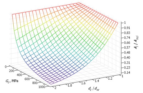
Fig. 3 presents the ratio of amplitudes as a function of coating material shear modulus and the coating material specific damping capacity under the assumption that 2 and 0.01.
Fig. 3The ratio of amplitudes Ai/Anci as a function of the coating material shear modulus Gc and the coating material specific damping capacity ξc
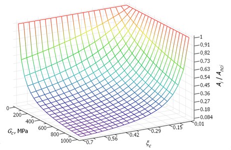
The assumed range of the shear modulus and the specific damping capacity of the damping coating material includes values of these parameters typical for both industrial rubber and plastics, such as polyurethane, polyethylene of high density or polyamide. Rubber-like materials usually have very good damping properties, but are accompanied by very low shear modulus values. Thus, although they are successfully applied in many different types of dampers [11], it can be seen in Fig. 3 that in the considered case such materials do not provide good results. Materials with good damping properties but higher shear modulus, such as typical polymers [12], provide much higher vibration damping efficiency. It is also visible in Fig. 2 that the relative thickness of the coating plays a major role in damping effectiveness – the increase in the ratio is accompanied by a slow increase in damping.
3. Conclusions
The presented model allows the maximum amplitude of coated helical spring vibrations to be calculated when the amplitude of excitation is known. The considerations proved that the resonant longitudinal vibration amplitudes of helical springs can be effectively reduced using damping coatings applied on their wires. It was shown that the material used for the coating should have properties characteristic for typical macromolecular plastics rather than rubber.
References
-
Berger C., Kaiser B. Results of very high cycle fatigue tests on helical compression springs. International Journal of Fatigue, Vol. 28, 2006, p. 1658-1663.
-
Yang O., Engel P., Shiva Prasad B. G., Woollatt, D. Dynamic response of compressor valve springs to impact loading. International Compressor Engineering Conference, 1996, p. 353-358.
-
Flenker Ch, Uphoff U. Efficient valve-spring modelling with MBS valve-train design. MTZ, Vol. 66, Issue 12, 2005, p. 946-950.
-
Liu H., Kim D. Effects of end coils on the natural frequency of automotive engine valve springs. International Journal of Automotive Technology, Vol. 10, Issue 4, 2009, p. 413-420.
-
Speckhart F. H., Mongold B. D., Chun H., Tyler V. M. Helical Coil Spring Damper Assembly. Patent US6789790 B2, 2004.
-
Kutzbach J. H., Menzel J. D. I. Anti-vibration Element. Patent DE10332637 A1, 2005.
-
Sai K. Valve Train of Internal Combustion Engine. Patent US8479696 B2, 2013.
-
Michalczyk K. Analysis of the influence of elastomeric layer on helical spring stresses in longitudinal resonance vibration conditions. Archives of Civil and Mechanical Engineering, Vol. 13, Issue 1, 2013, p. 21-26.
-
Rivin E. Passive Vibration Isolation. ASME Press, New York, 2003.
-
Michalczyk K. Influence of the elastomeric coating on parameters of steady state vibrations of coil springs in the resonance and outside it. Journal of Theoretical and Applied Mechanics, Vol. 52, Issue 2, 2014, p. 507-518.
-
Dziurdź J., Zawisza M. The investigation of the impact of changes in the characteristics of the rubber element on the effectiveness of torsional vibration damper. Vibroengineering Procedia, Vol. 6, 2015, p. 36-39.
-
Chung D. D. L. B. Review materials for vibration damping. Journal of Materials Science, Vol. 36, 2001, p. 5733-5737.
About this article

