Abstract
A dual-chamber air spring is an important vibration absorber. The shape and number of damping orifices directly influence the damping characteristics of dual-chamber air springs. The study investigates the application of damping characteristics of gas-liquid coupling dual-chamber air springs to mitigate the motion of a marine floating platform. An experimental method is used to analyze the influence of changes in the orifice number and shape on the damping characteristics of dual-chamber air springs given the same opening area. To analyze the effect of various orifice shapes, the study adopts a non-dimensional number to measure the image complexity, namely area/perimeter2 ratio. Additionally, two non-dimensional numbers are considered simultaneously, namely the orifice number and tightness factor, and the influence of changes in the orifice number and orifice position layout on damping characteristics of circular and square orifices is investigated, given the same opening area. The damping cloud map and a formula to calculate the damping for the gas-liquid coupling dual-chamber air springs are obtained by analyzing the experimental data. The proposed formula can be used to quickly calculate the damping coefficients of the dual-chamber air springs when the number and position layout of the orifices are known.
1. Introduction
Air springs are widely applied as vibration absorbers in large-scale industrial devices such as railway vehicles, ground automobiles, and mechanical equipment [1]. Enhancements in the design of various performance index requirements for vibration-damping systems led to the continuous exploration of new types of dampers [2, 3]. Thus, an increasing number of extant studies focus on dual-chamber air springs. The principle of vibration damping relates to the consumption of the vibration energy and reduction of the equipment amplitude to achieve vibration absorption. With respect to the industrial design of a vibration damping absorber, increasing the damping of a vibration damping absorber can achieve a better vibration-damping effect [4-6]. The industrial design of a vibration damping absorber necessitates accurate determination of the damping coefficient.
Bachrach and Rivin [7] investigated the complex stiffness of traditional air springs. Their investigation indicated that the functions for excitation frequency include stiffness and damping. Erin and Wilson [8] improved the standard model by considering the influence of the diaphragm, and this involved simply adopting the linear dynamic model consisting of a viscous damper, a hysteretic damper and a spring, and adjusting parameters of these units based on the experimental measurements. An experimental study by Kim and Lee [9] showed that the amplitude depends on nonlinear frequency behaviors. Additionally, Jing et al. [10, 11] proposed a method of nonlinear characteristic output spectrum (nCOS) to effectively solve the issue of air springs in a nonlinear vehicle suspension system based on the Volterra series expansion system principle. Rijken, Bian, Spillane, et al. [12-14] investigated the adoption of a vibration-absorbing system composed of a dual-chamber air spring and a liquid column to suppress the resonant response of a marine platform. They investigated the influence of a circular orifice ratio on the structural damping.
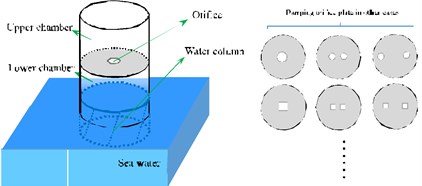
Currently, most extant studies on dual-chamber air springs mainly focus on traditional air springs. The compression of the gas in a traditional air spring is directly determined by the external load on the chamber. The load compresses the compression face of chamber with a piston. Therefore, the compression face and load are in the same phase and amplitude [15-19]. The gas-liquid coupling dual-chamber air spring that is applied for motion mitigation of a marine floating platform has two gas chambers, namely the upper gas chamber as an air store with a fixed volume and a lower gas chamber that is in contact with water, with volume changes based on the movement of the water column. The amount of compression gas in a chamber results from the relative displacement of a water column with respect to the top of the air spring. And the movement of the water column, which is similar to the action of a piston, is in different phases and amplitudes with the external excitation. Such differences reveal the unique characteristics of the gas-liquid coupling dual-chamber air spring.
The structure of a gas-liquid coupling dual-chamber air spring differs from that of a traditional air spring as shown in Fig. 1. Current studies mainly focus on traditional air springs. There is a paucity of research on gas-liquid coupling air spring dampers. Most previous studies on airflow via orifice plates involved adopting empirical formulas [20-22] and solely focused on circular orifices. Thus, there is a need to perform an in-depth investigation on the damping characteristics of gas-liquid coupling air spring dampers.
Zeng et al. [23] conducted the preliminary analysis for a gas-liquid coupling dual-chamber air spring and investigated the influence of parameters, such as the volume ratio of upper and lower chambers, orifice ratio, and amplitude and frequency of external loads, in a circular orifice case, on the damping and stiffness characteristics of dual-chamber air springs.
Fig. 1A schematic of gas-liquid coupling dual-chamber air spring and orifice plate
Current investigations on the damping characteristics of dual-chamber air springs mainly focus on the case of circular orifices, and to the best of the knowledge of the authors, there are no investigations that examine cases involving orifices with different shapes.
The present study investigates the damping characteristics of gas-liquid coupling dual-chamber air springs applied to the motion mitigation of a floating marine platform. The study uses an experimental method to examine the effect of the form of an orifice opening on the damping characteristics of dual-chamber air springs. A non-dimensional number termed the area/perimeter2 ratio is adopted to measure the various shapes of single orifices, and the damping coefficients of orifices with different shapes are analyzed. Finally, the study simultaneously considers two non-dimensional numbers, namely the orifice number and tightness factor and investigates the influence of different orifice numbers and layouts of orifices on damping characteristics, given the same opening area.
2. Mathematical calculation model
2.1. Energy consumption relationship
If a change in a thermodynamic system is sufficiently fast to ignore heat exchange with the environment, then such a change process is considered an adiabatic process, which can be adopted for the theoretical analysis of dual-chamber air springs [14].
Fig. 2A schematic of dual-chamber air springs
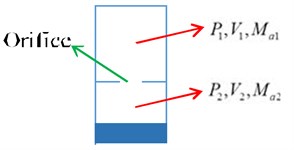
As shown in Fig. 2, the state equation of the open system gas in the adiabatic process is as follows:
where denotes the adiabatic exponent of gas and – constant. With respect to diatomic gases (such as nitrogen and oxygen, which are the main components of the earth’s atmosphere), .
The state equation of the gas in the upper chamber is as follows:
The volume in the upper chamber remains unchanged. Additionally, denotes initial air pressure of the upper chamber, denotes the changes in the air pressure in the upper chamber, denotes the mass of the initial gas in the upper chamber, and denotes the air mass flows into (or out of) small orifices.
The air mass that enters the upper chamber is as follows:
The state equation of gas in the lower chamber is as follows:
denotes the initial air pressure of the lower chamber, denotes the change in air pressure in the lower chamber, denotes the initial volume of the lower chamber, denotes volume change of the lower chamber, denotes the mass of the initial gas in the lower chamber, and denotes the outflow (or inflow) of air mass with respect to small orifices. It is noted that , and the initial air pressure of the upper chamber is the same as that of the lower chamber; that is, , where denotes atmospheric pressure. Thus, the length of the upper chamber is set as and that of the lower chamber is set as , and then the volume change of the lower chamber is obtained as follows:
where, denotes the motion change in the liquid column of the lower chamber. Based on the work–energy theorem, the damping dissipation energy within a period is equal to the work performed by the water surface of a liquid column on the air chamber as follows:
where denotes the work performed by the liquid column on the air chamber.
2.2. Viscoelastic model
In the study, the Kelvin viscoelastic model is adopted to investigate the damping characteristics of dual-chamber air spring dampers. The Kelvin model is composed of elastic and viscous components in a parallel configuration, and this is also termed the Kelvin-Voigt model. The elastic components follow Hooke’s law while the viscous components follow the law of viscosity. The strain and stress of viscoelastic objects involve different phases when subject to alternate loads. The objects exhibit the viscosity effect and cause the dissipation of energy, which is one of the important features of a dynamic viscoelastic property.
Fig. 3A schematic diagram of the principle of the Kelvin-Voigt model
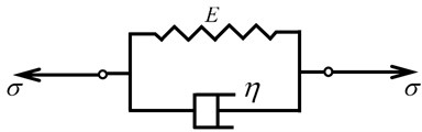
In the Kelvin-Voigt model, the strain , stress , and the change rate with respect to time are controlled by the following equation:
where denotes the elasticity modulus of Kelvin-Voigt material, and denotes viscosity.
2.3. Energy loss of viscoelastic model
Given the energy dissipation of materials, it is necessary to consider the deformation work applied by an external action on the objects. With respect to the one-dimensional axial loading, deformation work of unit volume corresponds to , and thus the total work is as follows:
It is assumed that the viscoelastic objects are subject to a one-dimensional harmonic strain denoted by , and the strain rate corresponds to ; thus, the stress can be expressed as follows:
It is observed that the stress response of viscoelastic objects is composed of two parts, namely an elastic term related to the storage modulus that is proportional to the strain and a viscous part that is related to the loss modulus that generates a phase difference of with respect to the strain. Within one cycle period, the work applied to the unit volume of objects is as follows:
The first term corresponds to reversible elastic potential energy while the second term represents the energy of viscous loss.
The harmonic strain can be represented as , and the energy of each cycle consumed for a unit volume is as follows:
From Eqs. (6) and (11), the following expression is obtained:
where denotes the maximum amplitude of motion change for a liquid column in the lower chamber.
3. Experimental design and setting
3.1. Design of the testing device
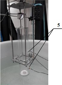
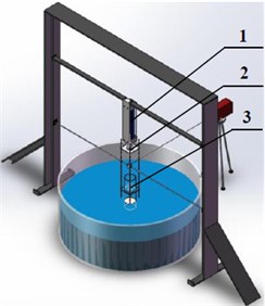
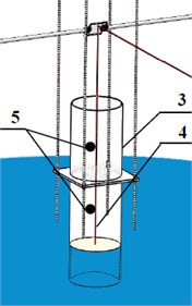
The study mainly focuses on investigating the dual-chamber air spring dampers applicable to the motion mitigation of a marine floating platform. To simulate the action of seawater in a more realistic manner, a vibration experiment device containing a gas-liquid coupling interaction system is designed, and it includes a cylindrical container, dual-chamber air spring, and servo control loading system. Additionally, the diameter of the cylindrical container corresponds to 1500 mm, which significantly exceeds that of the chamber (100 mm). As shown in Fig. 4, the test device specifically includes the following: 1) a hydraulic loading device, 2) a high sensitivity force sensor, 3) a dual-chamber air spring, 4) a throttle orifice plate, and 5) a high sensitivity air pressure sensor. Fig. 5 shows the loading system for the experimental device.
Fig. 4a) A photograph of the experimental device; b) a schematic of the experimental device; c) a dual-chamber air spring
a)
b)
c)
Additionally, , , and can be obtained after experimental measurement and simple data processing using the experimental device as shown in Fig. 4. Specifically, denotes the maximum amplitude of motion change for the liquid column in the lower chamber. The damping dissipation energy within one period can be obtained after substituting and into Eq. (6). The damping coefficient of the dual-chamber air springs, denoted as , is then obtained by substituting and into Eq. (12).
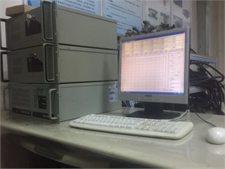
Fig. 5The data acquisition system
3.2. Setting of basic test parameters
In a previous study, the influences of the volume ratio of the upper and lower chambers, orifice ratio, as well as loading frequency and amplitude were analyzed with respect to the stiffness and damping of dual-chamber air springs [23]. Progress is made in this study. The influence of differences in the number and layout of orifices on the damping characteristics of dual-chamber air springs is investigated experimentally with the parameters given in Table 1. The condition is such that it is ensured that the volume ratio of the upper and lower chambers, orifice rate, loading amplitude ratio, and loading frequency remain unchanged.
Table 1The setting of basic parameters
Height of upper chamber () | Height of lower chamber () | Orifice ratio () | Loading amplitude ratio () | Loading frequency () |
150 mm | 200 mm | 0.4 | 0.01 | 1.649 |
In Table 1, denotes the volume ratio; denotes the orifice ratio, denotes the opening area, denotes the diameter of the chamber; denotes the ratio of the amplitude of outer excitation and height of the air chamber, and denotes the amplitude of outer excitation.
4. Results of experiment and discussion
4.1. Influence of differences in the shapes of orifices on the damping characteristics of dual-chamber air springs
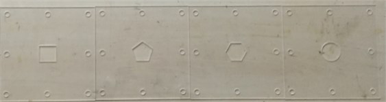
A previous study investigated the effects of the orifice ratio on the damping characteristics of dual-chamber air springs mainly based on the assumption that the damping orifices correspond to circular orifices [23]. However, this section mainly explains the influence of different orifice shapes on the damping characteristics of dual-chamber air springs, given the same opening area. The section mainly discusses the influence of square-shaped, pentagonal, and hexagonal orifices on the damping characteristics of dual-chamber air springs and makes a comparison with circular orifices.
To analyze the effect of various orifice shapes, a non-dimensional number termed the area/perimeter2 ratio to measure image complexity was adopted. This is more widely used in computer graphics, general image recognition, landscape ecology, and geographic information systems [24].
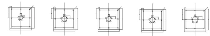
Fig. 6Experimental specimen of various shape orifices
The compactness of an object or shape is usually measured by area and perimeter . Several researchers adopt a non-dimensional number to measure the image complexity known as the area/perimeter2 ratio [25] that is given as follows:
The area/perimeter2 ratio of a circle is the highest in all cases. Thus, a modified ratio is used in this study, and this results in a uniform value for the circular shape that is based on the following relation: for a circle, which is calculated as follows:
With respect to shapes other than circular, .
Table 2 lists the modified area/perimeter2 ratio of the various orifice shapes discussed in this section.
The influence of the four differently shaped orifices on the damping coefficient of a dual-chamber air spring is shown in Fig. 7. Please refer to Appendix for details of the experimental data.
Table 2Modified area/perimeter2 ratio for various shapes of orifices
Square orifice | Pentagon orifice | Hexagon orifice | Circular orifice | |
0.886 | 0.9295 | 0.9515 | 1.0 |
Fig. 7Damping coefficient for different area/perimeter2 ratio
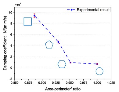
As shown in Fig. 7, various shapes of orifices, given the same opening area, exert extremely different influences on the damping characteristics of dual-chamber air springs. An increase in the modified area/perimeter2 ratio tends to decrease the damping coefficient of the air spring. Therefore, the damping coefficient is maximum when the orifice shape is square and minimum when the orifice shape is circular. From the viewpoint of viscous fluid dynamics, the damping generated by the damping orifice plate is divided into two parts when the dual-chamber air springs are subject to reciprocating motion. The first is the damping generated when the air in the dual-chamber air springs rubs against the wall of the damping hole. The second part involves vortices, which are generated as air quickly passes through the damping hole. Energy dissipation caused by the vortex leads to damping. These two types of damping are related to the perimeter of the hole. An increase in the perimeter of the hole increases the damping of the dual-chamber air springs. Given the same opening area, decreases in the perimeters of square, pentagon, hexagon, and circular orifices lead to decreases in the damping coefficient as shown in Fig. 7. Table 3 lists the perimeters of various shapes of orifices with the same opening area corresponding to 1.
Table 3The perimeter of various shapes of orifices with the same opening area corresponding to 1
Square orifice | Pentagon orifice | Hexagon orifice | Circular orifice | |
4.0 | 3.812 | 3.722 | 1.0 |
4.2. Influence of differences in the orifice number and position layout of circular orifices on the variation in damping characteristics
This section mainly analyzes the influence of differences in the number and layout of circular orifices on the variation in the damping characteristics of dual-chamber air springs, given the same orifice area.
In case of single orifices, the non-dimensional number mentioned in the above section, i.e., the modified area/perimeter2 ratio, can describe the influence of various orifice shapes on damping characteristics in a proper manner. However, in the case of multiple orifices, that non-dimensional number has limitations and cannot describe the effect of the orifice position layout.
To reflect the influence of the relative positions of multiple orifices on the damping characteristics of dual-chamber air springs, another non-dimensional physical quantity denoted is introduced to represent the compactness of orifices, i.e. the tightness factor. Additionally, the centers of orifices examined in the study are evenly arranged in an arc with different radii, and the tightness factor represents the ratio of the diameter of the arc with respect to that of the chamber. Given the same opening area, increases in the value of the tightness factor decrease the tightness.
The section mainly focuses on the case in which the orifice number is in the range of 2-5 with the value range of the tightness factor corresponding to 0.4-0.6.
Based on the experimental data processed in the section, the influence of the orifice number and tightness factor of circular orifices on the variation rule for the damping characteristics of dual-chamber air springs is obtained. Please refer to Appendix for the details on the experimental data.
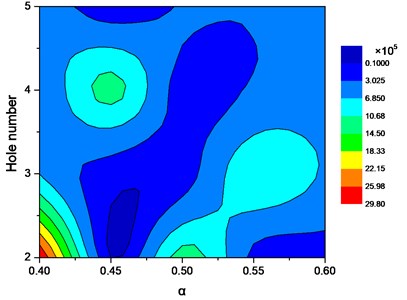
As shown in Fig. 9 and Fig. 10, the circular orifice number and the tightness factor exert a complex influence on the damping coefficient of the dual-chamber air springs. The maximum damping coefficient is associated with an orifice number corresponding to 2 and a tightness factor . The corresponding tests in the study are presented as case 1.2.1 and case 1.2.2 in Appendix. With respect to an orifice number corresponding to 4 and tightness factor , as shown in the figure, the damping coefficient corresponding to another peak area and corresponding tests in the study are given in case 1.4.2, case 1.4.3, and case 1.5.2 in Appendix.
With respect to the case of the circular orifice, both the orifice number and tightness factor change the damping coefficient of the dual-chamber air springs. As shown in the experimental results in Figs. 9 and 10, both the aforementioned parameters exert complex influences on the damping coefficient for the case investigated in the present study. Vortices generated by each hole interact with other vortices when the circular orifice number exceeds one. The effect of this type of interaction will vary with the orifice number. This type of interaction between vortices generated by multi-holes will also vary with variations in the hole spacing, which then leads to obvious changes in the damping coefficient due to the variations in the orifice number and the tightness factor. The damping coefficient can decrease due to the counteraction of different hole vortices within a certain parameter range or increase due to the enhancement of interaction in the range of the other parameters.
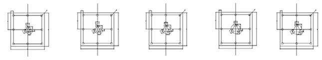
Fig. 8Experimental specimens with different orifice numbers and position layout of circular orifices
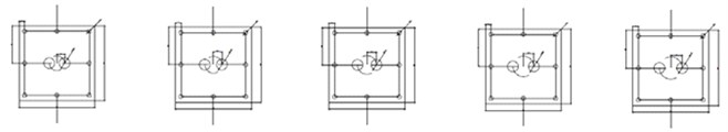
a) Two circular orifices
b) Three circular orifices
c) Four circular orifices
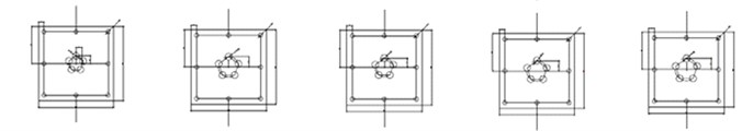
d) Five circular orifices
Fig. 9Damping coefficient of circular orifices with respect to the tightness factor and orifice number
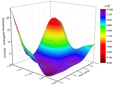
Fig. 10Cloud map of the damping coefficient for circular orifices with respect to the tightness factor and orifice number
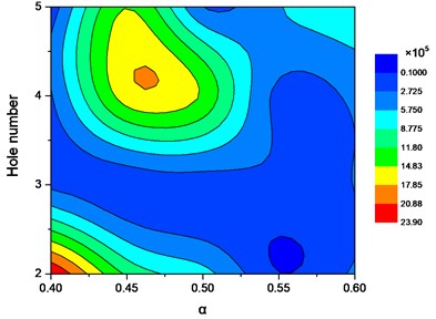
Additionally, the total perimeter of the damping holes increases with the number of the circular orifice, and subsequently the damping coefficient increases to a certain extent given the same opening area. The forementioned mechanisms affecting the damping value display a competing relationship. The final result of the damping coefficient reflects the comprehensive effect of different mechanisms. As shown in Fig. 9 and Fig. 10, the variations in the trend of the damping coefficient with differences in the number of circular orifice and the tightness factor is not monotonous, but evidently fluctuates with multiple extreme value points. In order to facilitate future engineering applications, based on the statistical analysis of the experimental results, a quick formula is proposed in Eq. (15) to calculate the damping coefficient of dual-chamber air springs. The damping coefficient of this type of a damping plate can be quickly calculated as long as the circular orifice number and tightness factor are substituted in Eq. (15).
In the study, the least square method is adopted to analyze the experimental data, and a formula to quickly calculate the damping coefficient for the dual-chamber air springs with respect to the circular orifices is obtained as follows:
where denotes the damping coefficient in the circular orifice case, denotes the number of orifice, and denotes the tightness factor.
Generally, the coefficient of determination is adopted for the analysis to fit the result reliability for evaluation, and is within the approximate range of 0-1. The value of is closer to 1, and thus its regression fitting effect is improved. Typically, it is considered that the model exceeding 0.8 corresponds to a relatively higher goodness of fit. Additionally, the value of the coefficient of determination is related to the number of independent variables. In order to check the accuracy of the model, the adjusted coefficient of determination is adopted in the study, and the coefficient of determination adjusted can reflect the level of fitting between the model simulation results and experimental data.
In this section, the coefficient of determination for fitting model corresponds to , which indicates that the model can adequately calculate and predict the experimental results, thereby validating the effectiveness of the regression equation fitted in the study.
In conclusion, it is possible to conveniently calculate the damping coefficient of circular orifice dual-chamber air springs by using Eq. (15) when the values of the orifice number and tightness factor are known.
4.3. Influence of differences in the orifice number and position layout of square orifices on the variations in damping characteristics
The section mainly analyzes the influence of differences in the orifice number and position layout of square orifices on the variations in the damping characteristics of dual-chamber air springs given the same opening area. The orifice number corresponds to the range 2-5 while the value range of tightness factor corresponds to 0.4-0.6.
Based on the experimental data processed in the section, the influence of differences in the number and tightness factor of square orifices on the variations in the damping characteristics of dual-chamber air springs can be obtained. Please refer to Appendix for the details on the experimental data.
As shown in Fig. 12 and Fig. 13, the differences in the number and tightness factor of square orifices exert different influences on the damping coefficient for dual-chamber air springs when compared with those of circular orifices. The maximum damping coefficient is associated with an orifice number corresponding to 2 and a tightness factor [0.4, 0.425] and [0.475, 0.525]. The corresponding tests in the study are represented by case 2.2.1 and case 2.2.3 in Appendix. With respect to an orifice number corresponding to 4 and a tightness factor [0.425, 0.475], as shown in the figure, the damping coefficient corresponding to another peak area and the corresponding test in the study is given in case 2.4.2 in Appendix.
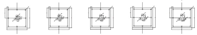
Fig. 11Experimental specimens with differences in the number and position layout of square orifices
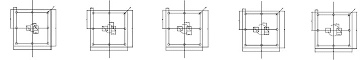
a) Two square orifices
b) Three square orifices
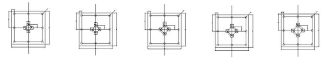
c) Four square orifices
d) Five square orifices
With respect to the case of the square orifice, the number and tightness factor of the orifices significantly influence the damping coefficient of dual-chamber air springs. In a manner similar to the discussion in section 4.2, number and tightness factor of the square orifices have a complex influence on the damping coefficient. Additionally, there are two competing mechanisms as shown in section 4.2. The damping coefficient fluctuates with respect to the number and tightness factor of the orifices, and corresponds to multiple evident extreme values. It should be noted that the dominant position of the two competing mechanisms varies when the shape of the orifices change from circular to square.
Fig. 12Damping coefficient of square orifices with respect to the tightness factor and orifice number
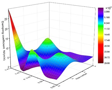
Fig. 13Cloud map of damping coefficient for square orifices with respect to the tightness factor and the orifice number
As shown in Fig. 12 and Fig. 13, Fig. 9 and Fig. 10, there are significant differences in the values of the damping coefficient, surface shape of the cloud map, and the position of the extreme points. In order to facilitate future engineering applications, based on the statistical analysis of the experimental results, a formula in Eq. (16) is proposed to quickly calculate the damping coefficient of dual-chamber air springs. The damping coefficient of this type of damping plate can be quickly calculated as long as the number and tightness factor of circular orifices are substituted into Eq. (16).
In this study, the least square method is adopted to analyze the experimental data, and a formula to quickly calculate the damping coefficient for the dual-chamber air springs with respect to the square orifices is obtained as follows:
where denotes the damping coefficient in the square orifice case, denotes the number of orifice, and denotes the tightness factor.
In the section, the coefficient of determination for the fitting model corresponds to , which indicates that the model accurately calculates and predicts the experimental result, thereby demonstrating the effectiveness of the regression equation fitted in the study.
In conclusion, it is possible to conveniently calculate the damping coefficient of square orifice dual-chamber air springs by using Eq. (16) when the values of the orifice number and tightness factor are known.
5. Conclusions
The dual-chamber air spring is an important vibration absorber, and the shape and number of damping orifices directly influence the damping characteristics of dual-chamber air springs. In this study, an experimental method is adopted to investigate the aforementioned problem. To analyze various orifice shapes, a non-dimensional number, the area/perimeter2 ratio, was introduced to measure image complexity and analyze the influence of various orifice shapes on the variations in the damping characteristics of air springs, given the same opening area. Additionally, the study introduced another non-dimensional number, the tightness factor , and analyzed the influence of the number and position layout of orifices on the variations in damping characteristics for circular and square orifices given the same opening area.
The following conclusions were drawn from the study:
1) Various shapes of orifices, given the same opening area, have significantly different influences on the damping characteristics of dual-chamber air springs. The damping coefficient of dual-chamber air springs tends to decrease with increases in the modified area/perimeter2 ratio. Therefore, the damping coefficient reaches a maximum when the orifice shape is square and a minimum when the orifice shape is circular.
2) The number and tightness factor of circular orifices exert complex influences on the damping coefficient of dual-chamber air springs. The maximum damping coefficient occurs when the orifice number corresponds to 2 and the tightness factor . When the orifice number corresponds to 4 and the tightness factor , another peak area for damping coefficient is observed in the corresponding figure.
3) With respect to the damping coefficient of square orifices dual-chamber air springs, the number of orifices and tightness factor do not correspond to the same as that of the circular orifices. The maximum damping coefficient is observed when the orifice number corresponds to 2 and tightness factor and . In the area where the orifice number corresponds to 4 and tightness factor , another peak area for damping coefficient is observed in the corresponding figure.
To facilitate future engineering applications, two formulae Eqs. (15) and (16) are proposed to quickly calculate the damping coefficient for circular and square orifices based on the statistical analysis of the experimental results. An investigation of the coefficient of determination for the fitting model verifies the effectiveness of the fitted regression equation. It is possible to conveniently calculate the damping coefficient of dual-chamber air springs using Eqs. (15) and (16) when the values of the orifice number and tightness factor are given.
References
-
Ibrahim R. A. Recent advances in nonlinear passive vibration isolators. Journal of Sound and Vibration, Vol. 314, Issue 3, 2008, p. 371-452.
-
Shimozawa K., Tohtake T. An air spring model with non-linear damping for vertical motion. Quarterly Report of RTRI, Vol. 49, Issue 4, 2008, p. 209-214.
-
Ning D. Y., Sun C. L. Study on active vibration isolation based on electromagnetic responses. IEEE International Conference on Computer Science and Automation Engineering, Vol. 2, 2012, p. 648-652.
-
Zeng X., Yu Y., Zhang L., et al. A new energy-absorbing device for motion suppression in deep-sea floating platforms. Energies, Vol. 8, Issue 1, 2015, p. 111-132.
-
Zeng X., Shen X., Wu Y. Governing equations and numerical solutions of tension leg platform with finite amplitude motion. Applied Mathematics and Mechanics, Vol. 28, Issue 1, 2007, p. 37-49.
-
Zeng X., Li X., Liu Y., et al. Nonlinear dynamic responses of tension leg platform with slack-taut tether. China Ocean Engineering, Vol. 23, Issue 1, 2009, p. 37-48.
-
Bachrach B. I., Rivin E. Analysis of a damped pneumatic spring. Journal of Sound and Vibration, Vol. 86, Issue 2, 1983, p. 191-197.
-
Erin C., Wilson B., Zapfe J. An improved model of a pneumatic vibration isolator: theory and experiment. Journal of Sound and Vibration, Vol. 218, Issue 1, 1998, p. 81-101.
-
Lee J. H., Kim K. J. Modeling of nonlinear complex stiffness of dual-chamber pneumatic spring for precision vibration isolations. Journal of Sound and Vibration, Vol. 301, Issue 3, 2007, p. 909-926.
-
Xiao Z., Jing X. An SIMO nonlinear system approach to analysis and design of vehicle suspensions. IEEE/ASME Transactions on Mechatronics, Vol. 20, Issue 6, 2015, p. 3098-3111.
-
Jing X. Nonlinear characteristic output spectrum for nonlinear analysis and design. IEEE/ASME Transactions on Mechatronics, Vol. 19, Issue 1, 2014, p. 171-183.
-
Rijken O., Spillane M., Leverette S. J. Vibration absorber technology and conceptual design of vibration absorber for TLP in ultradeep water. International Conference on Ocean, Offshore and Arctic Engineering, 2010, p. 629-638.
-
Bian X. S., Leverette S. J., Rijken O. R. A TLP solution for 8000 Ft water depth. International Conference on Ocean, Offshore and Arctic Engineering, American Society of Mechanical Engineers, 2010.
-
Spillane M. W., Rijken O. R., Leverette S. J. Vibration absorbers for deepwater TLP’s. The Seventeenth International Offshore and Polar Engineering Conference, International Society of Offshore and Polar Engineers, 2007.
-
Lee J. H., Kim K. J. A method of transmissibility design for dual-chamber pneumatic vibration isolator. Journal of Sound and Vibration, Vol. 323, Issue 1, 2009, p. 67-92.
-
Shin Y. H., Kim K. J. Performance enhancement of pneumatic vibration isolation tables in low frequency range by time delay control. Journal of Sound and Vibration, Vol. 321, Issue 3, 2009, p. 537-553.
-
Chang P., Han D. K., Shin Y., et al. Effective suppression of pneumatic vibration isolators by using input–output linearization and time delay control. Journal of Sound and Vibration, Vol. 329, Issue 10, 2010, p. 1636-1652.
-
Nieto A. J., Morales A. L., Trapero J. R., et al. An adaptive pneumatic suspension based on the estimation of the excitation frequency. Journal of Sound and Vibration, Vol. 330, Issue 9, 2011, p. 1891-1903.
-
Löcken F., Welsch M. The dynamic characteristic and hysteresis effect of an air spring. International Journal of Applied Mechanics and Engineering, Vol. 20, Issue 1, 2015, p. 127-145.
-
Pu H., Luo X., Chen X. Modeling and analysis of dual-chamber pneumatic spring with adjustable damping for precision vibration isolation. Journal of Sound and Vibration, Vol. 330, Issue 15, 2011, p. 3578-3590.
-
Liu H., Lee J. C. Model development and experimental research on an air spring with auxiliary reservoir. International Journal of Automotive Technology, Vol. 12, Issue 6, 2011, p. 839-847.
-
Sihong Z., Jiasheng W., Ying Z. Research on theoretical calculation model for dynamic stiffness of air spring with auxiliary chamber. Vehicle Power and Propulsion Conference, 2008.
-
Zeng X., Zhang L., Yu Y., et al. The stiffness and damping characteristics of a dual-chamber air spring device applied to motion suppression of marine structures. Applied Sciences, Vol. 6, Issue 3, 2016, p. 74.
-
Bogaert J., Rousseau R., Van Hecke P., et al. Alternative area-perimeter ratios for measurement of 2D shape compactness of habitats. Applied Mathematics and Computation, Vol. 111, Issue 1, 2000, p. 71-85.
-
Montero R. S., Bribiesca E. State of the art of compactness and circularity measures. Psychoanalysis and Contemporary Science, Vol. 4, Issue 27, 2009, p. 1305-1335.
About this article

The authors would like to express their gratitude for the financial support of the National Natural Science Foundation of China (Grant Nos. 11672306, 51490673, 11232012), the Strategic Priority Research Program of the Chinese Academy of Sciences (XDB22020101), and the National Basic Research Program of China (973 Program 2014CB046801).
