Abstract
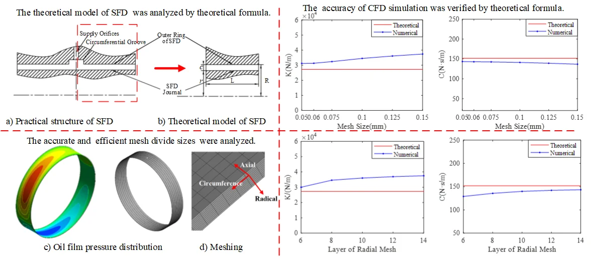
To accurately and efficiently calculate the dynamic characteristics of squeeze film damper (SFD), the influences of different parameters on computational fluid dynamics simulation were analyzed. The simulation was verified by theoretical formula of SFD based on the short bearing and semi-oil film hypothesis considering the oil film inertia force. Numerical simulation results have shown that mesh stiffness value can guarantee the convergence without influence on results. The mesh sizes have obvious influence on simulation results, while the influence of circumferential mesh size is comparatively weak. When there are more than 200-time steps in a cycle or more than 2 cycles are selected, it will take more computation time but with less influence on results. When the length-diameter ratio of SFD is smaller, the numerical calculation results have a better agreement with the theoretical results. The research will provide a reference for the options of simulation parameters of SFD while taking into account both analysis precision and computer time.
Highlights
- CFD simulation of squeeze film damper (SFD) was verified by theoretical formula.
- It provides a mesh size selection strategy for CFD simulation.
- The options of the transient solution method were analyzed.
1. Introduction
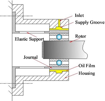
Squeeze film dampers (SFDs) aid to reduce rotor vibration and isolate a rotor from a stator or housing[1]. They are widely used in aircraft engines, high-speed centrifugal compressors and turbo-expanders[2]. Fig. 1 shows a schematic of SFD structure.
Fig. 1Schematic of SFD structure
The traditional method for SFD analysis usually involves a development of some rather complicated numerical calculation programs that may just focus on a simplified and specific physical model. The application of the general computational fluid dynamics (CFD) codes may make this analysis available and effective where complex flow geometries are involved or when more detailed solutions are needed [3-5]. Chen et al. [6] demonstrated the suitability of using CFD software for solving steady state hydrodynamic lubrication problems pertaining to SFDs. The steady-state laminar flow analysis was conducted on the theoretical 2D SFD. They observed that the temporal and convective effects tended to be opposite on the stiffness and damping coefficient for short SFD. Neadkratoke [7] modeled a 2D SFD with different amplitudes and frequencies in FLUENT. His results indicated that the forces increased with increased eccentricities and whirl frequencies of the journal. Khandare [8] also modeled a 2D SFD with different frequencies in FLUENT. After the successful use of the cavitation model in the 2D case, a 3D model with the same dimensions as the experimental setup was built and meshed. His work was validated by using the experimental results of Delgado[9]. Guo et al. [3] used CFX-TASC flow predicting the pressure distribution with a 3D SFD model, and analyzed the steady and dynamic characteristics of SFD. Xing [10] applied CFD-ACE establishing a two-phase flow model, and obtained both the damping coefficient and additional mass coefficient of SFD. Boppa et al. [11, 12] established the 3D numerical simulations model of SFDs in Fluent to determine the effect of changing groove size on the pressure profile. They observed that addition of the central groove reduced the rigidity developed in the film land when running at higher speeds. Wang [13] studied pressure distribution characteristics and oil film force characteristics by Fluent. Meanwhile, he also made a grid independence and time steps study according to the oil film force convergence in both vectors position on fixed coordinate system. Dousti [14] addressed the supply groove depth and pressurization effects on the behavior of open end squeeze film dampers using numerical CFD approach. Lee et al.[15] used CFD software to simulate the influence of oil-sealing ring, central groove and inlet on the dynamic characteristics of SFD. Yan et al. [16] established a SFD numerical simulation model by CFD software combined with multiphase flow theory. Based on dynamic mesh, Jiang et al. [17] carried out a numerical simulation study on SFD with a center groove structure. Zhou et al. [18] studied the effect of oil supply conditions on the damping characteristics of SFD with numerical CFD approach. Perreault et al. [19]provided the development of a CFD simulation model to study the thermohydrodynamic effects in SFDs. The results showed that the temperature of the lubricant was observed to rise with increasing whirl speed and eccentricity ratios in SFD. Ferfecki et al. [20] studied the pressure and velocity distribution of the segmented integral SFD. Their results showed that the supply pressure and the inertia of the oil had the influence on the pressure distribution and the hydraulic forces in the segmented integral SFD. , Zhou Hai-lun et al. [21] researched the air ingestion of open-ends SFD by CFD software CFX. The research shows that air ingestion will make the oil film damping tend to reduce with the increase of procession frequency and eccentricity ratio.
CFD software has been widely used in the study of SFD. Nevertheless, few researches focused on the research of calculation parameters of CFD in details, such as the mesh size of circumferential, radial and axial direction, calculation cycle numbers, time steps in a cycle and so on. The circumferential direction size of SFD is almost 1000 times of radial direction (oil film clearance) and 10 times of its axial direction. Therefore, reasonable mesh size in three directions (circumferential, axial, radial direction) is the key to obtaining accurate result and high-efficiency calculation.
In order to accurately and efficiently predict the dynamic characteristics of SFD, firstly, the numerical CFD results calculated by Ansys-CFX software were verified by the theoretical formula of SFD based on the short bearing and semi-oil film hypothesis considering the inertia force of the oil film. Then the influence of different calculating parameters is analyzed by CFD simulation results for SFD. Finally, the reasonable parameter settings of CFD simulation are provided for predicting SFD dynamic characteristics when a balancing act takes into account both the analysis precision and the time consuming of computer.
2. Dynamic characteristics of SFD considering oil film inertia force
The structure of SFD is usually simplified for deducing the dynamic characteristics formula of SFD, as shown in Fig. 2(a). Taking the middle line of central groove as the reference line, the left or right part of the structure is extracted as the theoretical model, which is shown in Fig. 2(b). The front and lateral view of theoretical model of SFD are shown in Fig. 3.
Fig. 2Structure of SFD
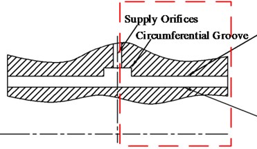
a) Practical structure
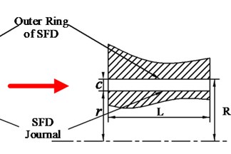
b) Theoretical model
Fig. 3Coordinate of SFD
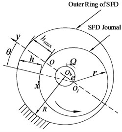
a) Front view
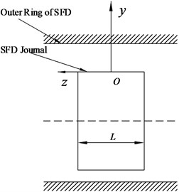
b) Lateral view
A rotating coordinate system is created in Fig. 3, where is the origin of the coordinate system of SFD. And the , and mean the circumferential, normal and the axial directions of journal surface respectively. is the center of the bearing housing, center of the journal, oil film thickness, angle which starts from the maximum oil film thickness (), eccentricity and precession angular velocity of journal motion, housing radius of SFD, journal radius, and oil film width.
In order to consider the oil film inertia, the axial pressure distribution equation can be obtained based on the short bearing assumption by Tichy and Ei-shafei [22] is as follows:
where is the viscosity of fluid, density of fluid. When , the pressure () is equal to atmospheric pressure, 0. Oil film pressure expression can be obtained by integrating the Eq. (1) with the boundary conditions as follows:
The radial force and tangential force can be obtained by integrating the Eq. (2) along the circumferential and axial direction respectively as follows:
In the above equations, and represent the boundary of oil film pressure region. Eq. (3) and Eq. (4) can be written as follows:
where and are radial and tangential forces of oil film respectively, which are dimensionless parameters. They are as follows:
where , , , is the Reynolds number of SFD, . And is damping coefficient, inertia force coefficient. The detailed expressions of and are list in Table 1 and 2 [23].
Table 1Damping coefficient C
Damping Coefficient of oil film | |||
Table 2Inertial force coefficient M
Inertia coefficient of oil film | |||
When the SFD works as circular centered-orbit motion in the steady state at the same frequency, the 0, and is equal to be constant, 0 and 1. Thereby the radial force and tangential force can be obtained as follows:
The equivalent oil film stiffness () and equivalent oil film damping () are the important characteristic parameters of SFD dynamic characteristic, they can be written as follows:
Considering that oil film inertia, equivalent stiffness () and equivalent damping () can be obtained based on the short bearing approximation theory, when the SFD works as circular centered-orbit motion in the steady state at the same frequency, they are written as follows:
3. CFD Model of SFD
According to the geometry of SFD shown in Fig. 3, the SFD parameters are list in Table 3. Fluid domain model can be established based on the parameters of the SFD. It is treated as computational domain. The hexahedral meshes are generated by the way of sweep method. The fluid domain mesh is shown in the Fig. 4, and Fig. 4(a) shows that the mesh density decreases to 10 % of simulation density in the circumferential, axial and radical directions for clear display. The thickness of film is too thin and the flow condition is usually treated as laminar [24]. Thereby, the influence of the side boundary layer mesh is not considered.
Table 3Structural parameters of SFD (mm)
Housing radial | Journal radial | Radial clearance | Length of bearing |
21.65 | 21.5 | 0.15 | 8.25 |
According to the short bearing assumption, the axial end of the “end land” is modeled as opening to ambient pressure [15]. The housing and journal of SFD is set to “wall”. The housing is stationary, while journal moves as circular centered-orbit motion in steady state as follows:
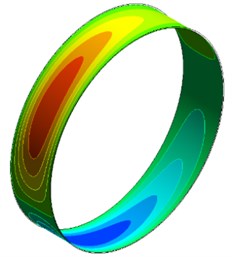
The oil density is 885 kg/m3 and viscosity 0.023 Pa.s. The whirl frequency of journal is 80 Hz. The oil film pressure distribution can be obtained by CFD software, as shown in Fig. 5. Then the radial force and tangential force can be obtained by Eq. (3) and Eq. (4). The equivalent oil film stiffness () and damping () can also be obtain by Eq. (11) and Eq. (12).
Fig. 4Flow domain mesh model
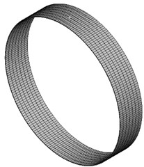
a) Mesh of fluid domain
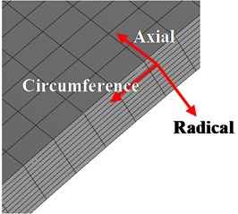
b) Local mesh of fluid domain
Fig. 5Oil film pressure distribution
4. Influence factors analysis of SFD dynamic characteristics by CFD simulation
In order to accurately and reasonably predict the dynamic characteristics of SFD, the influence of different calculating parameters on numerical simulation results of SFD is analyzed. Initial calculating parameters are chosen as follows.
The mesh size of circumference and axial is both 0.125 mm. The radial meshes are divided into 10 layers. Each cycle includes 50 steps and a total of 2 cycles. Eccentricity ratio is equal to 0.3.
4.1. Influence of mesh stiffness value
During the CFD calculation, when SFD operates with large amplitude orbital motions, mesh shape will change severely. It will lead to failure of calculation because of the negative mesh volume. If the mesh size is reduced, the problem of negative mesh volume will be strengthened. Although the problem can be alleviated by increasing the mesh size, it will obviously affect the calculation accuracy. Therefore, the problem of negative mesh volume cannot be solved by simply changing mesh resolution. The CFX software provides the function of mesh stiffness adjustment, which can improve the ability to resist deformation for mesh by changing the “Mesh Stiffness Value”. It will obviously ease the problem of negative mesh volume.
In order to study the influence of predicting the dynamic characteristics of SFD by adjusting mesh stiffness value, a series of values of mesh stiffness are selected respectively for calculating the film stiffness and damping of SFD. They are 1×10⁻⁵, 1, 3, 5, 10, 50, 100, where the default value of mesh stiffness is equal to 1. The calculation results for the film stiffness and film damping with different mesh stiffness value are shown in the Fig. 6.
Fig. 6 shows that the mesh stiffness value has few influences on film stiffness and film damping. Therefore, changing “Mesh Stiffness Value” can only guarantee the calculation to be finished, but few influences on calculation results.
Fig. 6Stiffness and damping of SFD versus different mesh stiffness
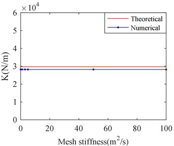
a) Film stiffness versus mesh stiffness
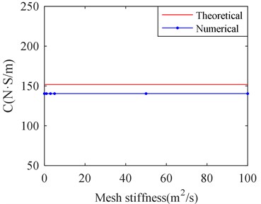
b) Film damping versus mesh stiffness
4.2. Influence of calculation cycle numbers
In order to select suitable calculation cycle numbers, different calculation cycle numbers are selected for calculating the equivalent stiffness and damping of SFD by CFX. They are respectively 1, 2, 5, 10, 20 and 50 cycles. The results are shown in Fig. 7.
Fig. 7Stiffness and damping of SFD versus different cycle number
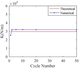
a) Film stiffness versus cycle number
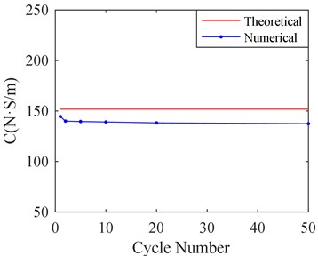
b) Film damping versus cycle number
Fig. 7 shows that calculation cycle numbers obviously affect the results calculated by CFX. When more than 2 cycles are selected, the calculating results are almost identical. Therefore, it is suitable to select 2 calculation cycles, when a balancing act takes into account both the analysis precision and the time consuming of computer.
4.3. Influence of mesh size
To conduct the mesh independence study, the mesh sizes of radial, axial and circumferential direction are adjusted respectively for simulation.
4.3.1. Influence of size of radial mesh
When the size of radial meshes is adjusted, the sizes of circumference and axial meshes remain 0.125 mm. The adjusting of radial meshes size is realized by changing the layer number of radial mesh. Five kinds of layer numbers of radial mesh are selected, which are 6, 8, 10, 12 and 14. Fig. 8 shows the film stiffness and damping of SFD, which are obtained by CFD calculation with five kinds of layer number of radial mesh.
Fig. 8Stiffness and damping of SFD versus different layer of radial mesh
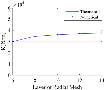
a) Film stiffness versus layer of radial mesh
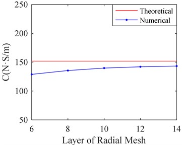
b) Film damping versus layer of radial mesh
It can be seen from Fig. 8 that the film stiffness and damping tend to be convergent as the layer number of radial mesh increases. When the layer number is larger than 10, the film stiffness and damping changes a little as the layer number increases. The film damping value is closer to the theoretical value with the bigger layer number while the film stiffness is further from theoretical value. It may be related to the size of circumference and axial mesh. Therefore, the influence on the size of circumference and axial mesh should be studied.
4.3.2. Influence of size of circumference and axial mesh size
Firstly, make the size of circumference and axial mesh equal. Six kinds of circumference and axial mesh sizes are selected for simulation. They are listed in Table 4.
According to Table 4, it can be seen that quantity of mesh and calculation time remarkedly increases as the mesh size decreases. The corresponding results are shown in Fig. 9.
Table 4Number of mesh for different sizes
Mesh Sizes / mm | Number of Mesh | Calculation Time / min |
0.05 | 4416000 | 909 |
0.06 | 3118000 | 446 |
0.075 | 1988000 | 276 |
0.1 | 1127000 | 194 |
0.125 | 716000 | 130 |
0.15 | 498000 | 118 |
Fig. 9 shows the calculation result with different sizes of circumference and axial mesh. It can be seen that the film stiffness and damping tends to convenge and becomes closer to the theoretical value as the mesh size decreases. When the mesh size is less than 0.06 mm, the film stiffness and damping has little change as the mesh size decreases. However, it will take much more time to the process of calculation according to Table 4.
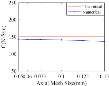
To save the computer time, the influence of mesh size in circumference and axial direction on simulation is studied respectively. Make the axial mesh size equal to 0.06 mm, and the circumference mesh size 0.06 mm, 0.125 mm, 0.25 mm, 0.5 mm, 1 mm, 2 mm and 4 mm respectively. The corresponding calculation results are shown in Fig. 10.
It can be seen from the Fig. 10 that there is little influence on simulation results with decrease of circumferential mesh size when the mesh size is less than 1 mm. Therefore, make mesh sizes equal to 1mm in circumferential direction, which cannot obviously affect the results.
Fig. 9Stiffness and damping of SFD versus different mesh sizes
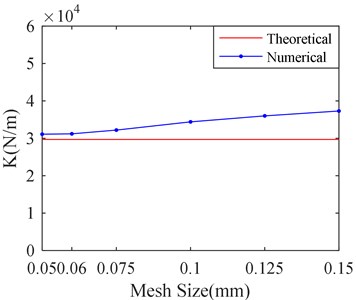
a) Film stiffness versus mesh sizes
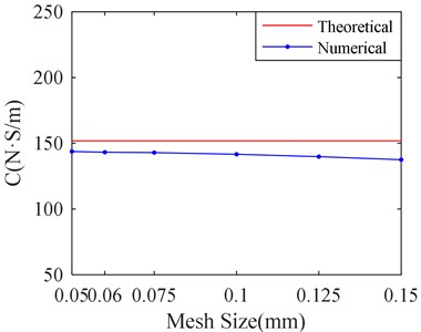
b) Film damping versus mesh sizes
Fig. 10Stiffness and damping of SFD versus different circumferential mesh sizes
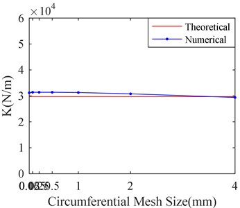
a) Stiffness versus circumferential mesh sizes
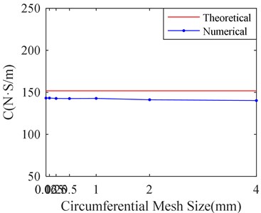
b) Damping versus circumferential mesh sizes
In order to study the influence of mesh size in axial direction for simulation results, six kinds of mesh sizes are selected. They are 0.05 mm, 0.06 mm, 0.075 mm, 0.1 mm, 0.125 mm, and 0.15 mm. The mesh size in circumference direction is set to 1 mm. The corresponding calculation results are shown in Fig. 11.
Fig. 11Stiffness and damping of SFD versus different axial mesh sizes
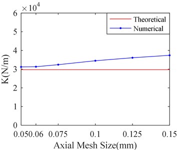
a) Stiffness versus axial mesh sizes
b) Stiffness versus axial mesh sizes
Fig. 11 shows that there is little influence on simulation results with decrease of Axial mesh size when the mesh size is less than 0.06 mm. Therefore, it is suitable to make mesh sizes equal to 0.06 mm in axial direction. From the Fig. 8 to Fig. 10, it can be seen that the axial mesh size has more obvious influence on the simulation result than the circumference mesh size. It may be attributed to the fact that the circumference dimension is larger than the axial.
According to Table 5, the calculation time is 446 minutes, when the circumference and axial mesh size are both 0.06 mm. However, the calculation time is only 91 minutes, when the circumference mesh size is 1mm and axial mesh size is 0.06 mm. And the relative calculation error is only 0.3 % for the two kinds of mesh generation while the calculation time is nearly five times different. Therefore, the circumference mesh size is set to 1mm and axial mesh size is 0.06 mm in the follow simulation, it can take into account a balance between both analysis precision and the time consuming of computer.
The axial mesh size was set as 0.125 mm, the radial mesh was divided into 10 layers, the number of calculation cycle was 2, the calculation time step was 200 steps/T and the mesh stiffness value was 1. The oil film pressure of mesh size in different circumferential direction is shown in Fig. 12. The oil film pressure distribution is shown in Fig. 12(a) when the circumferential mesh size is 0.125 mm. Fig. 12(b) shows the oil film pressure distribution when the circumferential mesh size is 1 mm. The oil film pressure curve at the same monitoring point under the two circumferential mesh sizes is shown in Fig. 12(c). The monitoring point is located at the negative axis and the center of the axis in the model.
Fig. 12Oil film pressure
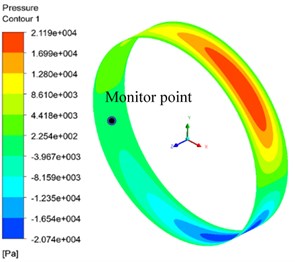
a) Circumference direction mesh 0.125 mm
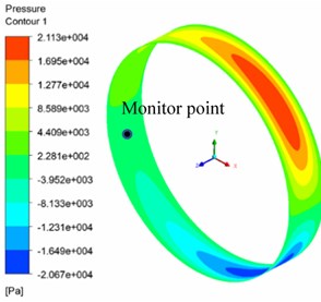
b) Circumference direction mesh 1 mm
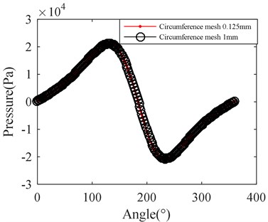
c) Curve of the pressure
4.4. Influence of time steps in a cycle
The simulation for SFD dynamic characteristic is a transient calculation with numerical CFD approach. Numbers of time steps in a cycle has important influence on simulation results. More time steps will lead to a sharp increase in calculation time, while less time steps may lead to an inaccurate calculation result. In order to study the effect of time steps in a cycle, five kinds of time-steps are selected, which are 50, 100, 200, 400, and 600 steps respectively in a cycle. The corresponding calculation results are shown in Fig. 13. The other parameters are based on the before study.
It can be seen from Fig. 13 that the film stiffness and damping tend to be convergent as the number of time steps increases in a cycle. When the number of time steps is more than 200, the film stiffness and damping changes a little as the number of time steps increases. Therefore, it is suitable to make time steps in a cycle equal to 200.
Fig. 13Stiffness and damping of SFD versus different time-steps in a single cycle
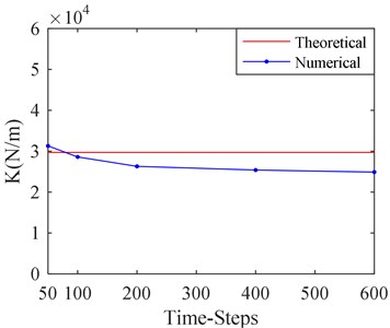
a) Stiffness versus time-steps
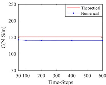
b) Damping versus time-steps
4.5. Influence of length to diameter ratio of SFD
It can be seen from the above calculation results that a certain error still exists between the theoretical and numerical solution, although smaller mesh size, more numbers of cycles and time steps are selected. It may lie in two aspects: one is the theoretical formula ignoring the change of oil film pressure in radial direction, and the other is due to the simplification in the theoretical calculation formula based on the short bearing assumption.
Fig. 14Stiffness and damping error of SFD versus length to diameter ratio
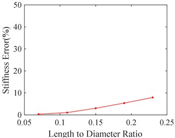
a) Stiffness error versus length to diameter ratio
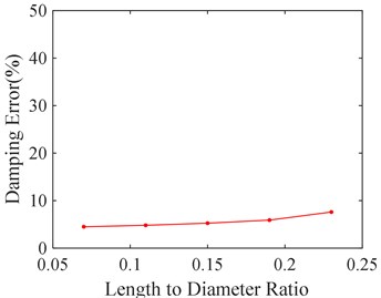
b) Damping error versus length to diameter ratio
In order to study the effect of the short bearing assumption, five kinds of length to diameter ratio of SFD are selected, 0.07, 0.11, 0.15, 0.19, and 0.23 respectively. The corresponding calculation errors between the theoretical and numerical solution are shown in Fig. 14. It can be seen from Fig. 14 that calculation error shrinks as the length to diameter ratio decreases. It is mainly because smaller length to diameter ratio is more qualified for short bearing assumption.
5. Conclusions
In order to accurately and efficiently predict the dynamic characteristics of SFD, the influence of mesh stiffness, calculation cycle numbers, calculation time steps, mesh size and damper length-diameter ratio were analyzed by using CFD software. The conclusions of the study are as follows:
1) Mesh stiffness value has few influence on the calculation results of film stiffness and damping for SFD, but it can guarantee the convergence of numerical simulations and avoid negative mesh.
2) When the number of calculation cycle is 2, the equivalent stiffness and equivalent damping tend to be convergent.
3) When the calculation time-step is 200 steps/T, the equivalent stiffness and equivalent damping tend to be convergent.
4) When the mesh sizes in axial, circumferential and radical directions are 0.06 mm, 1 mm and 10 layers, the CFD results are efficient and accurate.
5) When the length-diameter ratio of the damper is smaller, the numerical calculation results are consistent with the theoretical results well.
The research will provide a reference for the numerical simulation parameter selection of SFD dynamic characteristics when both the analysis precision and the time consuming of computer is taken into account in balancing act.
References
-
San Andrés L., Koo B., Jeung S.-H. Experimental force coefficients for two sealed ends squeeze film dampers (Piston Rings and O-Rings): an assessment of their similarities and differences. Journal of Engineering for Gas Turbines and Power, Vol. 141, 2019, p. 76224.
-
Sarkar S. Numerical Investigation of Vapor and Gaseous Cavitation in Squeeze-Film Damper Bearings. University of Cincinnati, Ohio, 2018.
-
Guo Z., Hirano T., Kirk R. G. Application of CFD analysis for rotating machinery – part I: Hydrodynamic, hydrostatic bearings and squeeze film damper. Journal of Engineering for Gas Turbines and Power, Vol. 127, Issue 2, 2005, p. 445-451.
-
Zhao H.-M., Zheng J.-J., Xu J., et al. Fault diagnosis method based on principal component analysis and broad learning system. IEEE Access, Vol. 7, 2019, p. 99263-99272.
-
Zhao H.-M., Zheng J.-J., Deng W., et al. Semi-Supervised broad learning system based on manifold regularization and broad network. IEEE Transactions on Circuits and Systems, Vol. 67, Issue 3, 2020, p. 983-994.
-
Chen P. Y. P., Hahn E. J. Use of computational fluid dynamics in hydrodynamic lubrication. Proceedings of the Institution of Mechanical Engineers, Part J: Journal of Engineering Tribology, Vol. 212, Issue 6, 1998, p. 427-436.
-
Neadkratoke T. Numerical Investigation of Flow Fields and Forces for 2-D Squeeze Film Dampers. Texas A&M University, 2011.
-
Khandare M. N. Numerical Simulation of Flow Field Inside a Squeeze Film Damper and the Study of the Effect of Cavitation on the Pressure Distribution. Texas A&M University, 2010.
-
Delgado Marquez A. A Linear Fluid Inertia Model for Improved Prediction of Force Coefficients in Grooved Squeeze Film Dampers and Grooved Oil Seal Rings. Texas A&M University, 2008.
-
Xing C., Braun M. J., Li H. Damping and added mass coefficients for a squeeze film damper using the full 3-D Navier-Stokes equation. Tribology International, Vol. 43, Issue 3, 2010, p. 654-666.
-
Boppa P., Sekaran A., Morrison G. Effects of adding a central groove to the squeeze film damper lands. Proceedings of the ASME Fluids Engineering Division Summer Meeting, Nevada, USA, 2013.
-
Boppa P. Numerical Simulation of Squeeze Film Dampers and Study of the Effect of Central Groove on the Dynamic Pressure Distribution. Texas A&M University, 2011.
-
Wang Z. L. Numerical and Experimental Study on Damping Characteristics of Squeeze film Damper for Turboshaft Engine. Harbin Institute of Technology, Harbin, 2013.
-
Dousti S., Gerami A., Dousti M. A numerical CFD analysis on supply groove effects in high pressure,open end squeeze film dampers. International Journal of Engineering Innovation and Research, Vol. 5, Issue 1, 2016, p. 80-89.
-
Lee G. J., Kim J., Steen T. Application of computational fluid dynamics simulation to squeeze film damper analysis. Journal of Engineering for Gas Turbines and Power, Vol. 139, Issue 10, 2017, p. 102501.
-
Yan S. Analysis and Experiment Study on Dynamic Characteristics of Squeeze Film Damper. Nanjing University of Aeronautics and Astronautics, Nanjin, 2017.
-
Jiang Q. Numerical Simulation of Cavitation Field and Dynamic Characteristics of Squeeze Film Damer. Dalian: Dalian Maritime University, 2017.
-
Zhou H. L., Zhang M., Cheng X. M., et al. Effects of oil supply conditions on equivalent damping and circumferential position damping of squeeze film damper. Journal of Mechanical Engineering, Vol. 54, Issue 6, 2018, p. 215-223.
-
Perreault M., Hamzehlouia S., Behdinan K. Application of computational fluid dynamics for thermohydrodynamic analysis of high-speed squeeze-film dampers. Transactions of the Canadian Society for Mechanical Engineering, Vol. 43, Issue 3, 2019, p. 306-321.
-
Ferfecki P., Zapoměl J., Gebauer M., et al. A computational fluid dynamics investigation of the segmented integral squeeze film damper. MATEC Web Conference, Vol. 254, 2019, p. 08005.
-
Zhou H.-L., Chen X., Zhang Y.-Q., et al. An analysis on the influence of air ingestion on vibration damping properties of squeeze film dampers. Tribology International, Vol. 145, 2020, p. 106168.
-
Crandall S. H., Ei Shafei A. Momentum and energy approximations for elementary squeeze-film damper flows. Journal of Applied Mechanics, Vol. 60, Issue 3, 1993, p. 728-736.
-
Della Pietra L., Adiletta G. The squeeze film damper over four decades of investigations. Part I: Characteristics and operating features. The Shock and Vibration Digest, Vol. 34, Issue 1, 2002, p. 3-26.
-
Adiletta G. An insight into the dynamics of a rigid rotor on two-lobe wave squeeze film damper. Tribology International, Vol. 116, 2017, p. 69-83.
About this article

This work is financially supported by the National Natural Science Foundation of China (No. 51505300), Scientific Research Fund of Education, Science and Technology Department of Liaoning Province (No. 2019-ZD-0233, No. JYT19061).
