Abstract
Numerical methods were conducted to simulate the characteristics of SFD under different clearance, eccentricity and precession angular velocity and verified by bidirectional excitation experiments, which is comparatively leading initiative in characteristic measurement of SFD. In addition, finite difference method was introduced to derive Reynolds equation and SOR method to obtain the distribution of oil film, the convergence was also mathematical proof. The results indicate the rotor system keep large vibration state for a long time due to the increasing of actual critical speed of system, which result from the oil film stiffness increases nonlinear excessively with the increase of eccentricity; clearance make a great influence on SFD, especially SFD with large radial size should be kept within 2 ‰.
1. Introduction
Aero-engine structural faults are mostly result from vibration, which seriously affect the performance and endurance. Improving dynamic characteristics of the rotor-support system is a effective way to reduce the engine vibration [1, 2]. SFD (short for Squeeze Film Damper) has been widely used in aero-engines for stabilization and vibration control since its performance was convinced by Cooper in 1970s [3]. Well-designed SFD have been proven to have excellent damping performance, generally reduce vibration by more than 60 % [4, 5]. In order to explore dynamic characteristics of SFD of a certain aero-engine, difference method is used to simulate which verified by the bidirectional incentives experiment in this paper.
2. Modeling and simulation
2.1. Finite difference method modeling principle
For the convenience of comparison between simulation and experimental data, the parameters of SFD in simulation are exactly the same as real one. The width of oil film is 29 mm, average radius of film ring is 154.85 mm, and the kinetic viscosity of 4050 lubricating oil at 40 °C is 0.023368 (pa·s).
Simulation is to obtain the equivalent stiffness and damping of film, difference method is taken into the Reynolds equation to calculate radial and circumferential reaction force under different parameters. The basic idea of finite difference method is to mesh the domain of the problem first, then replace the derivative of definite problem with difference quotient on grids in order to discretizing the original problem into a difference format, which is convenient for finding a numerical solution. Following differentials are defined:
When oil film ring and journal do not rotate and the oil film journal only makes a circular precession motion around the center of the oil film ring, the Reynolds equation at this time is:
Substituting the differentials above into Eq. (1), obtained Eq. (2):
Among them:
2.2. Convergence proof
Taking SFD in an ideal state, the flow filed of damper is cut away from the maximum oil thickness, nodes are generated in direction and nodes are generated in direction in the discrete region, calculation precision improved with number of meshes increased. Iterative method is generally used to solve equations, in order to improve the iteration speed, successive over-relaxation method is used here:
Take:
Substituting Eq. (4) into Eq. (2):
Among them:
Thus, Eq. (5) can be expanded as:
It’s easy to prove that the coefficient matrix , , , stay positive when and approaches 0. Thus, the coefficient matrix of Eq. (6) is a diagonally dominant matrix, which proven the SOR method is convergent when , where is the relaxation factor, taken here 0.95.
According to Table 1, 2, maximum error decreased by 1/3 with step size decreased to 1/2.
Table 1Exact solutions at partial nodes and numerical solutions for variable step size
(, ) | (, ) | |||
(1/5, 1/5) | (3/5, 2/5) | (2/5, 3/5) | (4/5, 4/5) | |
(1/10, 1/20) | 154359.52 | 373772.41 | 524645.75 | 125927.06 |
(1/20, 1/40) | 242487.34 | 377547.15 | 546633.40 | 124413.70 |
(1/40, 1/80) | 281143.55 | 382724.82 | 549250.31 | 121603.36 |
(1/80, 1/160) | 298539.74 | 380216.77 | 549386.72 | 119813.64 |
Exact solution | 298626.85 | 380908.76 | 551032.22 | 120778.78 |
Table 2Relative error of numerical solutions at partial nodes for variable step size
(, ) | (, ) | |||
(1/5, 1/5) | (3/5, 2/5) | (2/5, 3/5) | (4/5, 4/5) | |
(1/10, 1/20) | 48.31 % | 1.87 % | 4.79 % | 4.26 % |
(1/20, 1/40) | 18.80 % | 0.88 % | 0.80 % | 3.01 % |
(1/40, 1/80) | 5.85 % | 0.48 % | 0.32 % | 0.68 % |
(1/80, 1/160) | 0.03 % | 0.18 % | 0.30 % | 0.80 % |
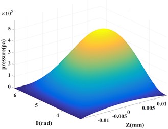
Fig. 1 and 2 show the pressure distribution of SFD based on short bearing hypothesis and difference method, they are almost identical which verified the convergence of difference method used in this paper.
Fig. 1Pressure distribution based on short bearing hypothesis
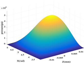
Fig. 2Pressure distribution based on difference method
2.3. Simulation
In order to obtain oil film characteristics of SFD under different clearance, eccentricity, precession angular velocity, change one geometric parameter and keep other parameters unchanged. Simulation results are shown in Table 3, Table 4 and Table 5, where is oil film radius clearance, is journal eccentricity, is journal precession angular velocity, and is radial and circumferential reaction force of film, and is equivalent stiffness and damping of film.
Table 3Oil film stiffness and damping under different clearance
(mm) | (rads/s) | (N) | (N) | (N/m) | (N/(m/s)) | |
0.1 | 0.2 | 100 | 109.71 | 395.83 | 3.66E+06 | 4.20E+04 |
0.2 | 0.2 | 100 | 61.71 | 222.66 | 1.54E+06 | 1.77E+04 |
0.3 | 0.2 | 100 | 27.43 | 98.96 | 4.57E+05 | 5.25E+03 |
Table 4Oil film stiffness and damping under different eccentricity
(mm) | (rads/s) | (N) | (N) | (N/m) | (N/(m/s)) | |
0.15 | 0.1 | 100 | 27.32 | 189.50 | 1.82E+06 | 4.02E+04 |
0.15 | 0.2 | 100 | 109.71 | 395.83 | 3.66E+06 | 4.20E+04 |
0.15 | 0.3 | 100 | 268.92 | 641.29 | 5.98E+06 | 4.54E+04 |
0.15 | 0.4 | 100 | 554.09 | 960.25 | 9.23E+06 | 5.09E+04 |
Table 5Oil film stiffness and damping under different precession angular velocity
(mm) | (rads/s) | (N) | (N) | (N/m) | (N/(m/s)) | |
0.15 | 0.2 | 100 | 109.71 | 395.83 | 3.66E+06 | 4.20E+04 |
0.15 | 0.2 | 200 | 219.43 | 791.67 | 7.31E+06 | 4.20E+04 |
0.15 | 0.2 | 300 | 329.14 | 1187.50 | 1.10E+07 | 4.20E+04 |
0.15 | 0.2 | 400 | 438.86 | 1583.30 | 1.46E+07 | 4.20E+04 |
0.15 | 0.2 | 500 | 548.57 | 1979.20 | 1.83E+07 | 4.20E+04 |
0.15 | 0.2 | 600 | 658.29 | 2375.00 | 2.19E+07 | 4.20E+04 |
Fig. 3Reaction force under different parameters
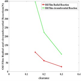
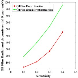
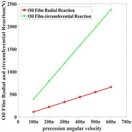
Table 3 and Fig. 3 show that with other parameters unchanged, the reaction force, equivalent stiffness and damping of oil film are gradually reduced as clearance increased.
Simulation results with eccentricity in 0.1, 0.2, 0.3, 0.4 are shown in Table 4. Equivalent stiffness and damping of oil film increased as eccentricity increase and stiffness grew faster. Strong nonlinear were started to manifested in film force when eccentricity ≥ 0.3, which indicates when rotor passing through the critical state of system under large unbalanced response, it won’t pass fast and keep large vibration for a long time due to the increasing of actual critical speed of system which result from stiffness increases nonlinear excessively.
Table 5 and Fig. 3 indicate that circumferential and radial reaction force increased linearly as precession angular velocity increased, and circumferential reaction force increased faster. Equivalent stiffness of oil film increased while damping of oil film kept unchanged, which indicates that increase the journal’s speed can’t reduce the vibration very well.
3. Experiment
The bidirectional excitation experiment uses bidirectional excitation tester to simulate SFD in working condition with oil. Fig. 4 shows the main structure of bidirectional excitation test rig, the center axis of exciter, flexible rod, impedance head and the center axis of transfer should be kept in the same straight line to reduce the influence of additional bending moment during installation, phase of two transfer should be offset with 90°. During the experiment, two force fork transmit the excitation of exciters to SFD to simulate its whirl which eliminated the interference of rolling bearing and coupling on results. Harmonic excitations with different frequencies, phase displacement 90° are generated by signal generator during experiment, amplitude of two harmonic signals keep the same. Excitation frequencies are 50, 100, 150, 200, 250, 300 Hz (corresponding precession angular velocity ). In order to ensure measurement accuracy, squirrel cage and mandrel are fit for interference.
Fig. 4SFD bidirectional excitation test rig
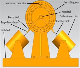
Fig. 5Schematic configuration of SFD
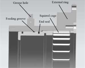
Fig. 5 shows assembly of the damper and squirrel cage, oil fills rapidly through the feeding groove to compensate for leakage and suppress cavitation effect. In most cases, two O-rings act as end seals to reduce leakage. Mechanical impedance principle is used to fit excitation and response signals to obtain oil film stiffness and damping.
Fig. 6 shows experimental data are basically fitted with simulation, the error may result from factors such as end seal and inlet oil pressure are not taken into account in theoretical model. Future research directions is study the effects of these factors on oil film characteristics.
Fig. 6Comparison of experimental data and simulation data under different parameters
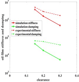
a) Clearances
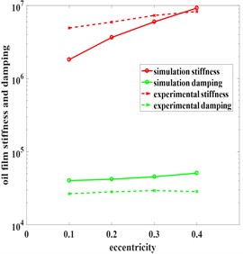
c) Eccentricity
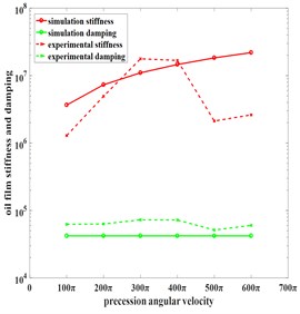
b) Precession angular velocity
4. Conclusions
Numerical and experimental search indicated that film stiffness and damping are reduced with increase of clearance, oil sealing and extrusion effect of dampers become weaker. For dampers with small radial size, clearance should be maintained at 1 ‰-3 ‰; and for dampers with large radial size, the upper limit should be reduced to 2 ‰. In addition, increasing the precession angular velocity appropriately helps to improve film stiffness, but less impact on damping. Oil film squeeze enhanced with increase of eccentricity, but it has great damage to critical stability of rotor system. Thus, eccentricity should be controlled within a suitable range.
References
-
Chen Zhao Research on Dynamic Characteristics Analysis Method of Projectile Squeeze Film Damper. Nanjing University of Aeronautics and Astronautics, Nanjing, 2008.
-
Su Chunfeng Research on Dynamic Characteristics of Elastic Ring Squeeze Film Damper. Shenyang Institute of Aeronautical Industry, Shenyang, 2009.
-
Cooper S. Preliminary investigation of oil-films for the control of vibration. Proceedings of the Lubrication and Wear Convention, London, 1963.
-
Zhang Ming Simulation and Experiment Study on Dynamic Characteristics of Squeeze Film Damper. Shenyang Aerospace University, Shenyang, 2018.
-
Yang Xiguan Stability Analysis of Rotor System Under The Action of Airflow Excitation Force. Nanjing University of Aeronautics and Astronautics, Nanjing, 2008.
About this article

