Abstract
In view of the large maneuvering overload of the rotor system in Unmanned Aerial Vehicle (UAV), the dynamic characteristics of rotor system under large maneuvering overload conditions were analyzed in this paper. The finite element model of rotor system under large maneuvering overload was first established by Timoshenko beam element theory and finite element method. The motion differential equations of the rotor system were derived by Lagrange equation, and the additional damping matrix, stiffness matrix and excitation force were obtained. Critical speeds and unbalance response were calculated by characteristic equation method and Newmark-β numerical integration method respectively. The calculation results showed that the additional damping and stiffness leaded the critical speeds of the rotor system to change under large maneuvering flight, and the additional excitation force resulted in a certain static displacement of the whirling orbits.
1. Introduction
The maneuvering overload of mainstream fighters is generally less than 9 g because of the pilot's tolerance ability. With the continuous improvement of technology, the UAV appears frequently in modern local wars, mainly be responsible for tasks such as intelligence reconnaissance, military strikes, information confrontation, communication relay and logistics support, and its role is becoming more and more significant [1]. Compared with the traditional fighters, the UAV does not need to consider the tolerance ability limit of the human body.
In order to improve the maneuverability greatly, the maneuvering overload of the UAV will far surpass 9 g in the future, and higher requirements are needed for the rotor system in the UAV’s engine than in traditional fighters, therefore, it is necessary to study the dynamic characteristics of the rotor system under large overload conditions (10 g-30 g).
A lot of research has been done on dynamic characteristics of rotor system under maneuvering flight by many scholars. Studies showed that maneuvering will add an additional load on the rotor system. As the overload increases, the effect will become more pronounced, and the dynamic characteristics of the rotor system will change [2].
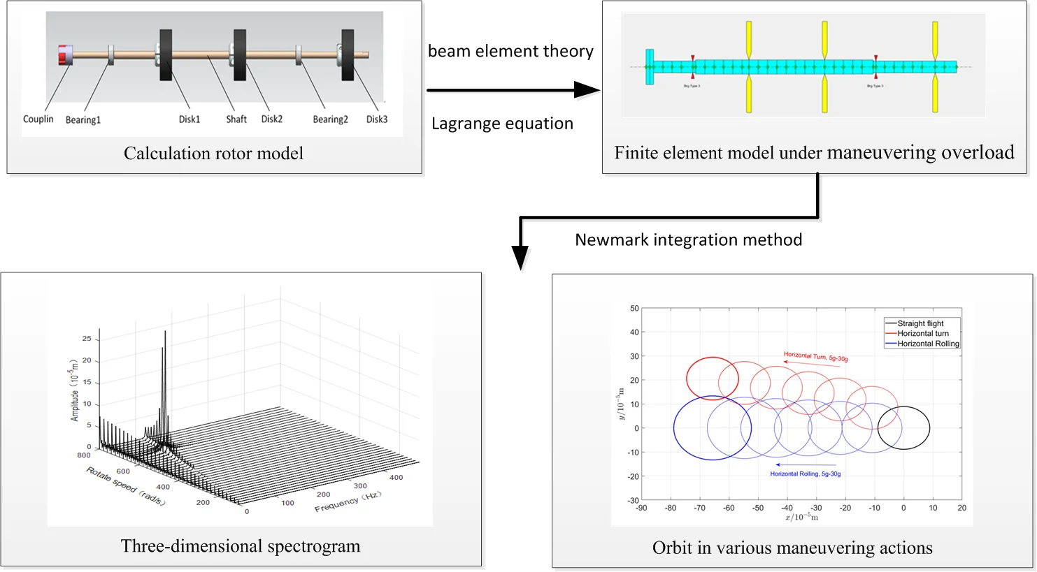
The differential equations of motion under arbitrary maneuvering conditions were derived making use of Lagrange equation, beam element theory and finite element method for the rotor system, and the equations were calculated by characteristic equation method and numerical Newmark- integration method. Then the dynamic characteristics of rotor system were analyzed in this paper.
2. Mathematical model
According to the small deformation hypothesis, the bending deformation of the rotor is generally much smaller than the span of the rotor. Under the circumstances, the differential equations of motion of the rotor system can be modeled by the finite element method and Timoshenko beam theory which can take advantage of shear deformation and moment of inertia.
The equation of motion of the rotor system is expressed by Eq. (1) when the maneuvering overload is not considered:
where represents the displacements of generalized degrees of freedom, represents the inertia matrix of rotor system, represents the damping matrix, represents the gyroscopic matrix, represents the stiffness matrix, represents the speeds of rotor, and represent unbalance force and external incentives on rotor system respectively.
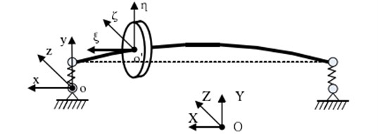
The coordinate system is established to describe the motion of the rotor system considering the maneuvering overload, as shown in Fig. 1, where represents fixed coordinate system on the ground, represents static coordinate system of rotor, and represents rotating coordinate system of the disk.
Fig. 1Coordinate of the rotor system
According to the literatures [3, 4], the differential equation of motion of a disk under arbitrary maneuvering flight condition can be obtained by using the Lagrange equation:
where is the displacements of generalized degrees of freedom for the disk, , , and represent the mass, damping, gyroscopic and stiffness matrix of the disk respectively. is the external incentives on disk, , , and represent the additional damping matrix, stiffness matrix, and excitation force, the expressions are as follows:
where represents the mass of the disk, , , represent the displacements of the aircraft along the axes of , , , , , represent the angular velocity of the aircraft along the axes of , , , and represents the distance of disk and the origin of the coordinate system , is the polar moment of inertia, is diameter moment of inertia of the disk.
In a similar way, the differential equation of motion of the beam element can be obtained by Lagrange equation:
where, is the displacements of generalized degrees of freedom for the beam element, , , and are the mass, damping, gyroscopic and stiffness matrix of the beam element respectively, and is the external incentives on the beam element. , , and represent the additional damping matrix, stiffness matrix and excitation force respectively.
,, , and can be expressed by the physical parameters, shape functions of the beam element and the parameters of maneuvering flight of the aircraft in matrix form, here, the formulas are omitted due to space limitations.
Now the differential equations of motion of the disk and the beam element have been established, and the differential equation of motion of the whole rotor system can be obtained by assembling the motion equations of each shaft segment and disk:
where, is the displacements of generalized degrees of freedom for the rotor system, , , and are the mass, damping, gyroscopic and stiffness matrix of the rotor system respectively, and is the external incentives on the rotor. , , and represent the additional damping matrix, stiffness matrix and excitation force respectively.
3. Calculation model
Calculation model is showed in Fig. 2, the rotor system consists of two supporting and three disks, two of which are simple support disks, and the other one is a cantilever disk. The material of the shaft is 40Cr, and the material of disks is 45 steel, the main dimensions of the rotor are showed in Fig. 3, and other relevant data are showed in Table 1 and Table 2.
Fig. 2The Calculation rotor model
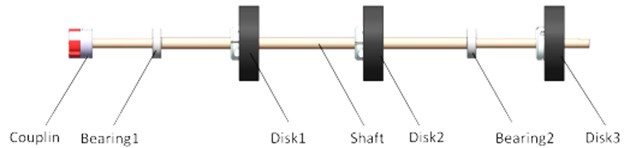
Fig. 3The main sizes of rotor
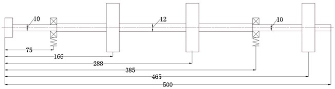
Table 1Stiffness of bearing (N/m)
Bearing1 | Bearing 2 | |
Stiffness | 1×10⁶ | 1×10⁶ |
Table 2Parameters of disks
Disk 1 | Disk 2 | Disk 3 | |
Quality/kg | 0.5344 | 0.5272 | 0.5272 |
Polar moment of inertia / kg·m2 | 0.0004 | 0.0004 | 0.0004 |
Unbalance amount / 10-5kg·m | 0.635 | 0.635 | 0.635 |
Table 3Parameters of maneuvering flight
Horizontal turn | Horizontal rolling | |
Turning and rolling radius (m) | 3 | 3 |
Angular velocity (rad/s) | 9.9 | 9.9 |
maneuvering overload (m/s2) | 294 | 294 |
Taking maneuvering overload as 30 g as an example to analyze the influence of large maneuvering overload on the dynamic characteristics of rotor system,the parameters under different maneuvering flight are showed in Table 3.
4. Results and discussions
4.1. Critical speeds calculation
The critical speeds of the rotor system can be calculated by the characteristic equation method [5] when Eq. (1) and Eq. (7) are converted to homogeneous equations. The first three orders critical speeds of the rotor regardless of maneuvering conditions are showed in Table 4. The calculation results of the critical speeds under maneuvering conditions are showed in Table 5.
According to the equation of motion of the rotor system under large overload conditions, maneuvering will provide additional stiffness, damping, excitation on the rotor system, the additional stiffness is very small compared with the inherent stiffness of the system. The additional damping directly relates the maneuvering flight of horizontal rolling. When the rolling angular velocity is sufficiently large, the additional damping can reach the magnitude of the rotor system’s inherent damping.
Therefore, when the aircraft makes a horizontal turn action, only a small additional stiffness is generated, and the critical speeds vary small, which can be neglected. While the aircraft performs the horizontal rolling motion, additional damping is generated which can cause a larger changes of the critical speeds. For the calculation model in this paper, the additional damping has the greatest impact on the first-order critical speed, which varies by about 2.45 % compared with the condition when the maneuvering overload is not considered.
Table 4The first three critical speeds regardless of maneuvering conditions
Order | Critical speed (rpm) |
First order | 4040 |
Second order | 6566 |
Third order | 15319 |
Table 5Effect of maneuvering flight on critical speed
Maneuver | Order | Critical speed (rpm) | Contrast with straight flight (%) |
Horizontal turn (30 g) | First order | 4039 | 0.025 |
Second order | 6566 | 0 | |
Third order | 15319 | 0 | |
Horizontal rolling (30 g) | First order | 3941 | 2.45 |
Second order | 6542 | 0.37 | |
Third order | 15223 | 0.63 |
4.2. Unbalanced response analysis:
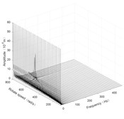
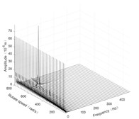
The steady response of the rotor system was solved by the Newmark- numerical integration method. The response results are plotted as three-dimensional spectrums, as shown in Fig. 4 to Fig. 6.
Fig. 4Three-dimensional spectrogram regardless of maneuvering conditions
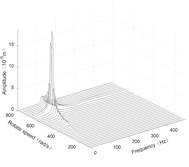
a) Disk 1 along -axis
b) Disk 1 along -axis
c) Disk 3 along -axis
d) Disk 3 along -axis
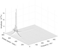
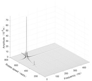
Fig. 5Three-dimensional spectrogram of horizontal turning
a) Disk 1 along -axis
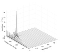
b) Disk 1 along -axis
c) Disk 3 along -axis
d) Disk 3 along -axis
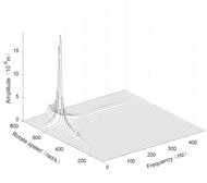
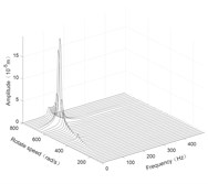
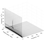
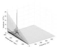
Fig. 6Three-dimensional spectrogram of horizontal rolling
a) Disk 1 along -axis
b) Disk 1 along -axis
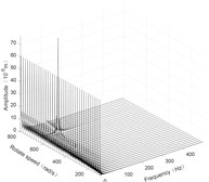
c) Disk 3 along -axis
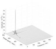
d) Disk 3 along -axis
Fig. 7Comparison of orbit in various maneuvering actions
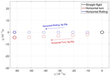
a) Disk 1 460 rad/s
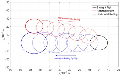
b) Disk 3 640 rad/s
According to the three-dimensional spectrogram, the additional centrifugal force and gyroscopic moment cause the rotor to generate a zero-frequency displacement component. When the aircraft makes horizontal turn action, the critical speeds change slightly, which can be neglected. When the aircraft performs the horizontal rolling, the critical speeds make a certain change, and this verifies the previous conclusion.
Due to the additional centrifugal force and gyroscopic moment generated by the maneuvering flight action, the whirling orbit of the rotor has made a certain static displacement, the comparing whirling orbits in each case are showed in Fig. 7. The horizontal turn action generates a static displacement along both and directions, while the horizontal rolling action generates a static displacement along x direction. In addition, the horizontal rolling action causes a variation of the critical speeds, which can be seen from the variation of the whirling radius.
5. Conclusions
The motion differential equations of the rotor system under arbitrary maneuvering conditions were first derived by beam element theory, finite element method and Lagrange equation, and the critical speeds and unbalance response were calculated by characteristic equation method and Newmark- numerical integration method in this paper. The simulation results showed that the maneuvering flight of the aircraft will have an important impact on the dynamic characteristics of the rotor system. Additional damping and stiffness generated under large maneuvering overload will change the critical speeds of the rotor system. The additional damping makes a greater influence than the additional stiffness on critical speeds. In addition, the maneuvering flight will generate additional excitation force on the rotor system, including centrifugal force and gyroscopic moment. The additional excitation force will cause a certain static displacement of the whirling orbits, which will increase the risk of rub between the rotor and the stator. Therefore, the design of clearance between rotor and stator in aero-engine under maneuvering flight conditions need to be focused.
References
-
Rong Hao, Tan Guojun Development status and trend of military UAV. Modern Business Trade Industry, Vol. 20, Issue 4, 2008, p. 111-112.
-
Chen Yushu, Zhang Huabiao Review and prospect on the research of dynamics of complete aero-engine systems. Acta Aeronautica Et Astronautica Sinica, Vol. 32, Issue 8, 2011, p. 1371-1391.
-
Zhu Changsheng, Chen Yongjun Vibration characteristics of aeroengine’s rotor system during maneuvering flight. Acta Aeronautica Et Astronautica Sinica, Vol. 27, Issue 5, 2006, p. 835-841.
-
Zhu Changsheng, Chen Yongjun General dynamic model of aeroengine’s rotor system during maneuvering flight. Journal of Aerospace Power, Vol. 24, Issue 2, 2009, p. 371-377.
-
Friswell Michael I., et al. Dynamics of Rotating Machines. Cambridge University Press, 2010.
About this article

