Abstract
In order to study the effects of maneuvering overload on the main shaft bearing (abbreviation: bearing) reaction force in an aero-engine, a bending-torsion coupling dynamic model of the dual rotor system under maneuvering overload was established. Combined with the output parameters of the system model, the bearing reaction force analysis model was established. The maneuvering overload parameters are input into system model. Newmark-β and Newton-raphson methods are used to obtain the bearing reaction force response, and the change laws of bearing reaction force under the different maneuvering overloads are analyzed. The results show that gravity will make the transient response of bearing reaction force offset, and maneuvering overload will make the offset shift. Maneuvering overload will cause bearing to produce a circumferential asymmetric reaction force. For bearing 1, the additional gyroscopic torque in maneuvering overload has a significant effect on the dynamic eccentricity, resulting in a larger offset of reaction force of direction. For bearings 3 and 4, reaction force of direction has a larger offset. Under the influence of bent-torsional coupling, the combined frequencies of base frequencies of rotational speed appear in the reaction force spectrum diagram.
Highlights
- Analysis of the reaction force of main shaft bearing
- The main shaft bearing of rotor under maneuvering overload
- Effect of rotor dynamic eccentricity on reaction force
- Frequency analysis of reaction force
1. Introduction
The time-varying loads of the main shaft bearing are significant reference for its design, and can also be used as the input parameters for its fatigue life test. The time-varying loads of bearings in aero-engine are divided into axial load and radial reaction force. The axial load depends on the aerodynamic load of engine compressor blades, while the radial reaction force is related to unbalanced excitation and additional excitation caused by maneuvering overload [1] Generally, the unbalanced excitation affects vibration characteristics of the rotor system [2-3], and furtherly, it affects the dynamic characteristics of the bearings reaction force. The maneuvering overload will results in dynamic eccentricity of the dual-rotor [4-7] and the impacts on the bearings reaction force are more significant. In some cases, an engine rotor system will have bending-torsion coupling vibration, which will change the frequency characteristics of the bearings reaction force. Therefore, the research on the characteristics of the bearings reaction force under maneuvering overload is of great significance to the fatigue life prediction of the bearings of the engine.
In this article, the dynamic model of dual-rotor system under maneuvering overload is first established, the transient response of the rotor system is obtained by Newmark-β and Newton-raphson numerical integration method, furtherly, the transient response is input into the bearing reaction force analysis model to obtain the time-varying reaction force of the bearings for analysis and research.
2. Model of engine dual-rotor system
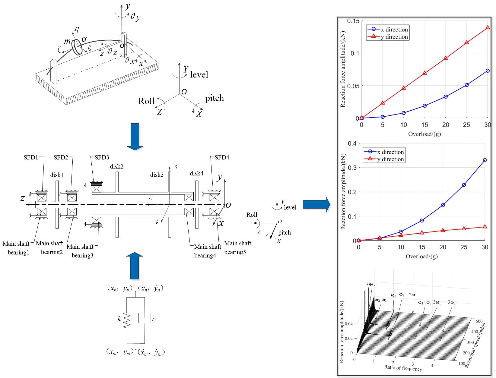
In order to establish dual-rotor system model of engine under maneuvering overload, coordinate systems should be established to describe maneuvering flight of aircraft and the rotating motion of an rotor. As shown in Fig. 1, ground coordinate system , carrier coordinate system and rotor coordinate system are established.
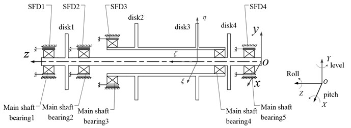
The mass eccentricity of disks cause bending-torsion coupling vibration, thus, the disk bending-torsion coupling dynamic model under maneuvering overload is established. By simplifying the structure of an engine, and the structure diagram of dual-rotor system is obtained, as shown in Fig. 2. Where is the carrier coordinate system in Fig. 1. The outer rings of the bearings 1, 2, 3, 5 are all connected with the squirrel cage elastic support and SFD in series, and the bearing 4 is connected with the high and low pressure rotor to couple two rotors.
Fig. 1Coordinate position relation
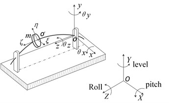
Fig. 2Dual-rotor system structural schematic
The translational kinetic energy , rotational kinetic energy , elastic potential energy and dissipative energy of disk are substituted into Lagrange equation. Let: . The disk bending-torsion coupling dynamic differential equation under maneuvering overload is obtained:
where, , , are the additional stiffness, damping and excitation generated by disk element under maneuvering overload condition. , , are the bending-torsion coupling matrix of disk element.
The model of beam element under maneuvering overload is established. Based on the relationship between element nodes, beam elements and disk elements are assembled. The dynamic differential equation of dual-rotor system considering bending-torsion coupling characteristics under mathematical model is obtained:
where, , , are the additional stiffness matrix, damping matrix and excitation vector generated by dual-rotor system under maneuvering overload, , , . , , are the coupling inertia, stiffness and damping matrix introduced by bending-torsion coupling characteristics.
Where, , , are the additional stiffness, damping and excitation generated by beam element under maneuvering overload condition. The expressions of , , are as follows:
where, , are mass and eccentricity of disk element, , are speed and acceleration of aircraft along axis, , are angular rate and angular acceleration of aircraft around axis.
3. Calculation method of the bearings reaction force
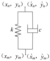
The bearing reaction force analysis model matching the transient response is established. Therefore, this section mainly introduces the bearing reaction force analysis method. The bearings are equivalent to spring-damping system. It can be seen form Fig. 3 that bearing 1 connects node and node , and its stiffness and damping coefficient of and direction are respectively , and , , and the components in and direction and resultant force of bearing 1 reaction force are as follows:
Fig. 3Spring-damping system
4. Calculation parameters
As shown in Table 1, 9 typical conditions are studied. The dual rotor speed ratio is 1.3. Where are 5, 10, 15, 20, 25, 30.
Table 1Parameters of maneuvering flight
Condition number | Maneuvering action | Maneuvering overload (g) | (m/s) | (rad/s) | (m/s) | (rad/s) | (rad/s) |
1 | Level | 0 | 15 | 0 | 0 | 0 | 0 |
2 | Hover | 0.1∙ | 0 | 0 | 0 | ||
3 | Pitch | 15 | 0 | 0 | 15 | 0 | –1.5 |
4 | Roll | 15 | 0 | 0 | –15 | 1.5 | 0 |
5. Calculation results and analysis of bearings reaction force
The dynamic differential equations of the rotor system are solved by Newmark-β and Newton-raphson numerical integration methods. The transient response is input into bearing reaction force analysis model to obtain the time-varying reaction force of the bearing, and effects of maneuvering flight, actions and overloads on the bearing reaction force are analyzed.
5.1. Effects of maneuvering flight on the transient response of bearings reaction force
Taking conditions 1 and 2 as examples, where is 15, the bearings do not bear gravity in direction when aircraft maintains level flight or hovers, so the transient response in direction of the bearings reaction force are studied.
Fig. 4 shows the transient response of reaction force of direction to the bearing 1 with aircraft keeping level flight and hovering when the low pressure rotor is at speed 280 rad/s. Observing Fig. 4(b), due to the existence of gravity, when aircraft is maintaining level flight, bearings reaction force of direction have a certain deviation. When the aircraft hovers, bearing is subjected to gravity in direction. Subjected to gyroscopic torque in direction, the rotor shaft will be whirled and there is dynamic eccentricity, so that the transient response of bearings reaction force are different from that of the level flight.
Fig. 4The transient response of reaction force of y direction to bearing 1
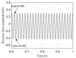
a) Hover
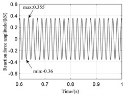
b) Level
Fig. 5The steady response of reaction force to bearings
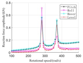
a) Bearing 1
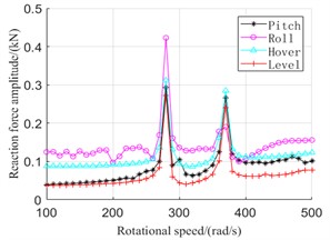
b) Bearing 3
5.2. Effects of maneuvering action on the steady response of bearings reaction force
Taking conditions 1, 2, 3 and 4 as examples, where is 15. The effects of maneuvering action on the steady response of the bearings are analyzed by solving the steady response of the bearings reaction force. Considering that bearing 1 and bearing 3 support the low and high pressure rotor respectively, the bearings 1 and 3 are selected as research objects.
Fig. 5 shows the steady response of the bearing 1 and 3, in which 280 rad/s and 370 rad/s correspond to the first-order critical speed of the high and low pressure rotor respectively. As shown in figure, when aircraft rolls, the bearings reaction force are the largest at speed 280 rad/s, while the bearings reaction force are the smallest at speed 370 rad/s. At the other speed, bearings supporting the low pressure rotor have smaller reaction force, while bearings supporting the high pressure rotor have larger reaction force during rolling. Although the rotor system is subject only to additional gyroscope torque during rolling, the rolling time is always very short, which makes rolling angular velocity larger, so impacts of rolling action on maintain level flight reaction force cannot be ignored. The Changes of impacts of hovering and pitching actions on reaction force of bearings supporting the low pressure rotor is not much, but for bearings supporting the high pressure rotor, bearings reaction force are larger than that of the pitching action.
5.3. Effects of overload on bearings reaction force
Taking conditions as examples, where is 5, 10, 15, 20, 25, 30, when the low pressure rotor is at speed 280 rad/s, the variation laws of the bearings reaction force amplitude caused by dynamic eccentricity with maneuvering load are analyzed.
Fig. 6 shows variation curve of amplitude of reaction force with maneuvering overload when aircraft hovers. When the aircraft hovers, the rotor system is subjected to additional centrifugal force of direction, and additional gyroscope torque acts in direction. Therefore, As shown in Fig. 6, the additional gyroscope torque has a more obvious influence on the rotor shaft dynamic eccentricity at the bearing 1, and for the bearings 3 and 4, the additional centrifugal force has a greater impacts on the offset of reaction force.
Fig. 6Variation curve of amplitude of reaction force with maneuvering overload
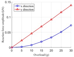
a) Bearing 1
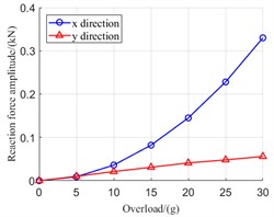
b) Bearing 3
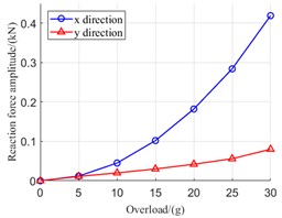
c) Bearing 4
5.4. Effects of maneuvering flight on frequency characteristics of bearings reaction force
Taking conditions 1 and 2 as examples, where is 15, the effects of maneuvering flight on the frequency characteristics of the bearings reaction force are studied.
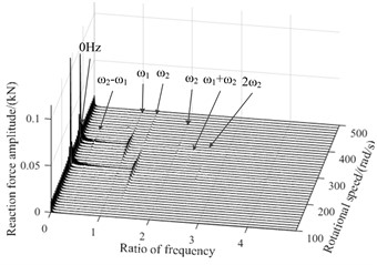
Fig. 7Three-dimensional spectral diagram of reaction force during hovering
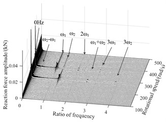
a) Bearing 1
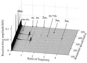
b) Bearing 3
Fig. 8Three-dimensional spectral diagram of reaction force during level
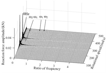
a) Bearing 1
b) Bearing 3
Fig. 7 and Fig. 8 are three-dimensional spectral graphs of the bearings reaction force during hovering and level flight respectively, where, and are base frequency of the low and high pressure rotor speed respectively, and the horizontal coordinate in the figure is the ratio of characteristic frequency to . As shown in figure, when aircraft is keeping level flight, the bearings reaction force have a zero frequency, mainly due to gravity, and the impacts of gravity on the bearing 5 are more significant. When aircraft hovers, rotor system is not only affected by gravity, additional excitation will also cause dynamic eccentricity, and with the increase of the low pressure rotor speed, the dynamic eccentricity will be greater, because the gyroscopic torque is related to speed. In the spectrum diagram of reaction force, there are not only frequency doubling components and of the fundamental frequency, but also and caused by high, low pressure rotor coupling and bending-torsion coupling.
6. Conclusions
In this paper, the change law of the bearing reaction force under maneuvering overload is analyzed. It is found that the transient response of the bearing reaction force is offset due to the gravity and the dynamic eccentricity of the rotor system. The steady state response of the reaction force varies with the bearing position and maneuvering action. For bearing 1, the additional gyroscopic torque in maneuvering overload has a significant effect on dynamic eccentricity, resulting in a larger offset of reaction force of direction. For bearings 3 and 4, the additional centrifugal force makes support reaction of direction have a larger offset. With the increase of maneuvering overload, the bearing reaction force caused by dynamic eccentricity increases. Due to the coupling of high and low pressure rotor and bending-torsion coupling, the frequencies doubling and combination of base frequencies of rotational speed appear in the reaction force spectrum diagram.
References
-
G. Wang, S. Liu, and Q. Zhu, “Study on dynamic characteristics of dual rotor-supporting system based on three-dimensional FEA model,” Transactions of Beijing Institute of Technology, Vol. 31, pp. 1292–1296, Nov. 2011, https://doi.org/10.15918/j.tbit1001-0645.2011.11.024
-
G. Luo, H. Zhou, F. Wang, and X. Guan, “Dynamic response of co-rotating and counter-rotating dual-rotor system supported on ball bearing,” Journal of Aerospace Power, Vol. 27, pp. 1887–1894, Aug. 2012, https://doi.org/10.13224/j.cnki.jasp.2012.08.031
-
X. Yang, G. Luo, Z. Tang, and F. Wang, “Modeling method and dynamic characteristics of high-dimensional counter-rotating dual rotor system,” Journal of Aerospace Power, Vol. 29, pp. 585–595, Mar. 2014, https://doi.org/10.13224/j.cnki.jasp.2014.03.015
-
N. Zheng, G.-H. Luo, X. Kuang, L.-J. Chen, and X.-M. Liao, “Dynamic characteristics of aero-engine’s rotor under large maneuvering flight,” Vibroengineering Procedia, Vol. 28, pp. 246–251, Oct. 2019, https://doi.org/10.21595/vp.2019.21044
-
Ananthan S. and Leishman J. G., “Helicopter rotor wake dynamics during simulated tactical maneuvers,” in Vertical Flight Society Annual Forum and Technology Display – Forum, Vol. 2014, p. 949, 2014.
-
R. Bouziani and N. Ouelaa, “Simulation of the dynamic behavior of a rotor subject to base motion under variable rotational speed,” Mechanics and Industry, Vol. 18, No. 3, p. 308, 2017, https://doi.org/10.1051/meca/2016056
-
M. Chen, Z. Jiang, G. Luo, and W. Wang, “The whirl direction and characteristics of rotor system under maneuvering flight,” Vibroengineering Procedia, Vol. 50, pp. 105–110, Sep. 2023, https://doi.org/10.21595/vp.2023.23493
About this article

The research is funded by National Science and Technology Major Project, Grant number J2019-Ⅳ-004-0071.
The datasets generated during and/or analyzed during the current study are available from the corresponding author on reasonable request.
The authors declare that they have no conflict of interest.
