Abstract
Analytical equations that describe the dynamic behavior of beams with a soft clamped end are very little treated in the literature. The paper aims to solve this problem by introducing a stiffness in the hinged end of the beam, respectively by comparing the bending moment in the clamped end with the slope in the hinge of the same end of the beam. The other end of the beam is permanently hinged. The characteristic equation for determining the eigenvalues and the modal function is deduced. The results show the first four vibration modes for seven stiffness values and the eigenvalues for eleven cases of soft clamped end.
Highlights
- Goals. Deducing an analytical model to compare the results obtained under ideal boundary conditions with experimentally measured values and to establish the degree of soft support of the clamped type.
- Analytical model. Analysis of the dynamic behavior of a normalized beam (L=1) under the action of its dead weight (q) and constant cross-section, starting from the case of a simply supported beam, where on one hinge it was introduced a bending moment equal to the bending moment of a clamped end multiplied by a stiffness coefficient k1. The Euler-Bernoulli model is used to obtain the characteristic equation.
- Results. The eigenvalues for the first six vibration modes for the stiffness coefficient k1=0, 0.1, 0.2, …, 0.9, 1.0 are presented, also the first four vibration modes for k1=0.0, 0.25, 0.50, 0.75, 0.85, 0.95 and 1.00 are illustrated.
- From the point of view of dynamic behavior, for stiffness values k1<0.5 the soft clamped end has a behavior very close to that of a hinged support. For stiffness values k1>0.5, the dynamic behavior of the beam is significantly affected and although the characteristic equation that describes the soft clamped end of the beam is a linear expression of k1, the effect of k1 in the modal function does not have a linear behavior.
- These relative deviations are very small and they decrease as the number of the vibration mode increases. From the analysis of the relative deviations of the eigenvalues by 10% (k1=0.1) compared to the ideal conditions (k1=0), they decrease from vibration mode 1 to 6 thus: e1=1.55% to e6=0.046% in the case of a hinge and from e1=3.13% and e6=2.01% the case of the clamped support, from k1=1 to k1=0.
- By introducing the stiffness coefficient k1, the characteristic equation allows us to calibrate analytically calculated values taking into account the results of experimental measurements on real structures, respectively to determine how soft the real clamped-type support is.
1. Introduction
Different types of failures can be occurred in structures. They can be caused by a lot of factors. It can be mentioned: improper manufacturing conditions, loosening of joints due to shocks and excessive vibrations, degradation caused by environmental conditions, material fatigue and exceeding the expected operating demands [1]. In the literature, there are a limited number of analytical equations to calculate the dynamic behavior of a soft clamped-type support for the beams. A new approach to soft clamping exploiting the vibrations from the perimeter of polygon-shaped resonators bonded to their tips has been demonstrated in [2]. In [3], the authors applied the theory of a doubly clamped non-uniform beam and analytically demonstrated how the dissipation dilution can be improved by modifying the beam shape to implement soft clamping.
In the paper [4], the authors present a weak solution for free vibration of multi-span beams subjected to general elastic boundary and coupling conditions. The general elastic boundary and coupling constraints of the multi-span beams are realized by applying the artificial stiffness-like spring technique. Other authors considered that for a doubly clamped beam the nonlinearities are weak, the beam is slender and elastic, shear deformations, longitudinal and rotational inertia, and gravity are neglected, and cross-sectional rotations and damping are small [5].
From a static or dynamic point of view, the analysis of beams with fixed ends involves the consideration of displacements and slopes perfect boundary conditions. Most researchers use measurement of natural frequencies to characterize imperfect boundary conditions, while others consider modal shapes to detect deviation from ideal conditions [4, 6].
An analytical model by using a negative stiffness resonator prototype to obtain the eigenfrequency for a compressed Euler beam clamped at both ends was analyzed in [7]. Lee [8] proposed an analytical model to distinguish the effects of axial and bending displacements and shear deformation on the natural frequencies of three‐layered beams using the transfer matrix method. Vibration and buckling of rotating composite cantilever beam with clamped-off the rotation axis was analyzed in [9] by using the Ritz method.
In this paper, the authors propose an analytical method regarding the dynamic behavior of a beam for which one of the hinge is considered to be an ideal spring with variable stiffness , so that for the zero value of the support is considered the hinge, and for the 1 value of , the support becomes clamped.
The analytical model proposed in this paper is important for comparing the results obtained analytically, with ideal contour conditions, with the experimentally measured values and to establish the degree of soft clamped-type support.
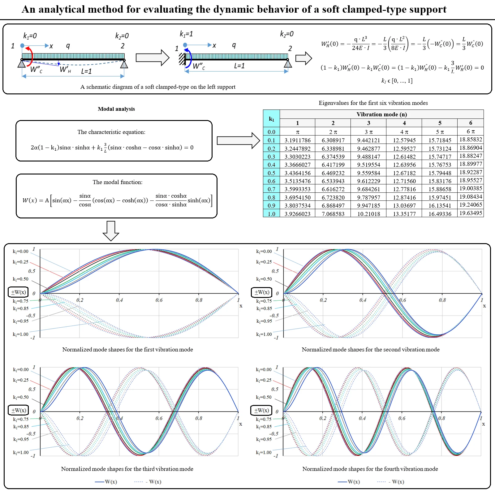
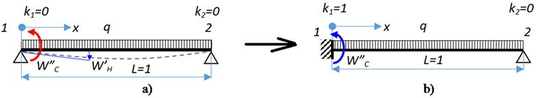
2. Soft clamped-type on the left support
In order to analyze the dynamic behavior of a normalized beam (1) under the action of its dead weight () and constant cross section, we considered the case of a simply supported beam (Fig. 1) where on the left hinge we introduced a bending moment equal to the bending moment of a clamped end [10, 11] multiplied by a stiffness coefficient .
It is considered that for 0, the support is a hinge (Fig. 1(a)) and for 1, the support becomes fix, or clamped (Fig. 1(b)). Any other value of is considered to be a soft clamped.
It is known from the strength of materials that for a hinge support located at 0, the boundary conditions for a beam loaded with its dead weight are: the deflection (0) and the bending moment (0) are equals to zero, and the slope has the expression:
where, [N/m] – is the load per unit of length (dead load); [m] – is the beam length; [N/m2] – is the Young’s modulus; [m4] – is the moment of the inertia of the cross section of the beam.
and for the clamped end at 0, the deflection (0) and the slope (0) are equals to zero, and the bending moment can be written as:
Fig. 1A schematic diagram of a soft clamped-type on the left support
Thus, if the bending moment from relation Eq. (2) is applied to the hinged at 0 (Fig. 1(a)), it becomes a clamped end, and the slope from Eq. (1) depending on the bending moment from Eq. (2) can be written:
or, expressing the bending moment from Eq. (3) and taking into account the stiffness , we have:
To satisfy the boundary conditions for 0 and , so that the left support to be a soft clamped end, we will obtain the relation:
From Eq. (5) it can be seen that for 0, the bending moment is zero (0), so in 0 we have a hinge, and for 1, the slope is zero (0), so we have a clamped end. For any other values of , in the left support we will find both bending moment and slope.
3. Modal analysis
For the Euler-Bernoulli model, it can be started from the spatial solution of the differential equation of bending vibrations, free and undamped:
where, – is the modal motion function; , , , – are integration constants that are obtained from the boundary conditions; – is the eigenvalue; – is the variable length of the normalized beam.
For clamped end and hinged end, at 0, the deflection is zero. Substituting 0 in Eq. (6), we get:
Entering the result from Eq. (7) in the relation Eq. (6), the slope and the bending moment become:
At the right end, for 1, on the hinge support, considering Eq. (7) in Eq. (6), the deflection and the bending moment are equals to zero:
The constants and are obtained from system Eq. (9):
By introducing the constants , and in relation Eq. (5), the characteristic Eq. (11) is obtained whose solutions give us the eigenvalues for each vibration mode and the modal function is presented in Eq. (12):
4. Results
The eigenvalues for the first six vibration modes (6) and different values of , solutions of Eq. (11), can be found in Table 1.
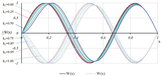
The first 4 (four) vibration modes for the following values of 0.0, 0.25, 0.50, 0.75, 0.85, 0.95 and 1.00 are illustrated in Figs. 2-5.
Fig. 2Normalized mode shapes for the first vibration mode
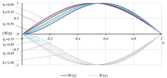
Fig. 3Normalized mode shapes for the second vibration mode
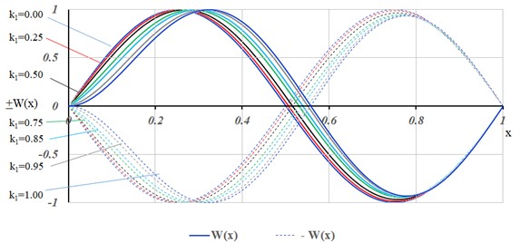
Fig. 4Normalized mode shapes for the third vibration mode
5. Conclusions
From the analysis of the figures from Figs. 2-5, for the first 4 vibration modes, it can be observed that for stiffness values 0.5, from the point of view of dynamic behavior, the soft clamped end has a behavior very close to that of a hinged support.
For stiffness values 0.5, the dynamic behavior of the beam is significantly affected and although the Eq. (5) that describes the soft clamped end of the beam is a linear expression of , the effect of in the modal function does not have a linear behavior.
Fig. 5Normalized mode shapes for the fourth vibration mode
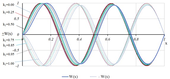
Table 1Eigenvalues for the first six vibration modes
Vibration mode (n) | ||||||
1 | 2 | 3 | 4 | 5 | 6 | |
0.0 | 2 | 3 | 4 | 5 | 6 | |
0.1 | 3.1911786 | 6.308917 | 9.442121 | 12.57945 | 15.71845 | 18.85832 |
0.2 | 3.2447892 | 6.338981 | 9.462877 | 12.59527 | 15.73124 | 18.86904 |
0.3 | 3.3030223 | 6.374539 | 9.488147 | 12.61482 | 15.74717 | 18.88247 |
0.4 | 3.3666027 | 6.417199 | 9.519554 | 12.63956 | 15.76753 | 18.89977 |
0.5 | 3.4364156 | 6.469232 | 9.559584 | 12.67182 | 15.79448 | 18.92287 |
0.6 | 3.5135476 | 6.533943 | 9.612229 | 12.71560 | 15.83176 | 18.95527 |
0.7 | 3.5993353 | 6.616272 | 9.684261 | 12.77816 | 15.88658 | 19.00385 |
0.8 | 3.6954150 | 6.723820 | 9.787957 | 12.87416 | 15.97451 | 19.08434 |
0.9 | 3.8037534 | 6.868497 | 9.947185 | 13.03697 | 16.13541 | 19.24065 |
1.0 | 3.9266023 | 7.068583 | 10.21018 | 13.35177 | 16.49336 | 19.63495 |
For this reason, the Figs. 2-5 show modal shapes with the stiffness with values of 0.75, 0.85, 0.95.
For the extreme cases: 0, the eigenvalues (Table 1) were obtained from the simply supported beam (hinged at both ends); respectively for 1, we find the eigenvalues for the beam clamped at one end and hinged at the other.
The procedure presented by the authors in this issue can also be applied for the soft clamped end at the right end of the beam (left end hinged) with the specification that Eq. (5) becomes:
because the slope has negative values.
The characteristic equation is identical to Eq. (11), so the eigenvalues are the same as the values from Table 1, and the modal function has the expression:
Mode shapes obtained in this case will be the mirror image of those presented in Figs. 2-5.
With relation Eq. (11) the eigenvalues can be determined for very small deviations from the ideal conditions of the fix or hinge type support. From the analysis of the relative deviations of the eigenvalues (Table 1) by 10 % (0.1) compared to the ideal conditions (0), respectively in the case of a hinge, for first vibration mode 1, it obtains: 1.55 % and for the sixth vibration mode: 0.046 %. Also, the relative deviations of the eigenvalues for the clamped support from 1 to 0.9: 3.13 % and 2.01 %. These relative deviations are very small and they decrease as the number of the vibration mode increases.
By introducing the stiffness coefficient , relation Eq. (11) allows us to calibrate analytically calculated values taking into account the results of experimental measurements on real structures, respectively to determine how soft the real clamped-type support is.
References
-
T. Lupu D. and G. G. R. A. M. I. C., “Detection of transverse cracks in prismatic cantilever beams affected by weak clamping using a machine learning method,” Analecta Technica Szegedinenesia, Vol. 16, No. 1, pp. 122–128, 2022.
-
M. J. Bereyhi et al., “Perimeter modes of nanomechanical resonators exhibit quality factors exceeding 109 at room temperature,” Physical Review X, Vol. 12, No. 2, May 2022, https://doi.org/10.1103/physrevx.12.021036
-
S. A. Fedorov et al., “Generalized dissipation dilution in strained mechanical resonators,” Physical Review B, Vol. 99, No. 5, p. 054107, Feb. 2019, https://doi.org/10.1103/physrevb.99.054107
-
D. Shi, Y. Tian, K. N. Choe, and Q. Wang, “A weak solution for free vibration of multi-span beams with general elastic boundary and coupling conditions,” Vibroengineering Procedia, Vol. 10, pp. 298–303, Dec. 2016.
-
Stefan Neumeyer and Jon Juel Thomsen, “Macromechanical parametric amplification with a base-excited doubly clamped beam,” in 11th International Conference on Vibration Problems, pp. 1–8, Sep. 2013.
-
D. Lupu, G. R. Gillich, D. Nedelcu, N. Gillich, and T. Manescu, “A method to detect cracks in the beams with imperfect boundary conditions,” Journal of Physics: Conference Series, Vol. 1781, No. 1, p. 012012, Feb. 2021, https://doi.org/10.1088/1742-6596/1781/1/012012
-
P. Fossat, M. Kothakota, M. Ichchou, and O. Bareille, “Dynamic bending model describing the generation of negative stiffness by buckled beams: qualitative analysis and experimental verification,” Applied Sciences, Vol. 13, No. 16, p. 9458, Aug. 2023, https://doi.org/10.3390/app13169458
-
J. W. Lee, “Free vibration analysis of three layered beams with a soft-core using the transfer matrix method,” Applied Sciences, Vol. 13, No. 1, p. 411, Dec. 2022, https://doi.org/10.3390/app13010411
-
T. Aksencer and M. Aydogdu, “Vibration of a rotating composite beam clamped-off the axis of rotation,” Composite Structures, Vol. 225, p. 111174, Oct. 2019, https://doi.org/10.1016/j.compstruct.2019.111174
-
P. Bratu, Analysis of elastic structures. Behavior in Static and Dynamic Actions. (in Romanian), IMPULS: București, România, 2011.
-
C. Zeveleanu and P. Bratu, Nonlinear Vibrations. (in Romanian), IMPULS: București, România, 2001.
About this article

The authors have not disclosed any funding.
The datasets generated during and/or analyzed during the current study are available from the corresponding author on reasonable request.
The authors declare that they have no conflict of interest.
