Abstract
Maneuvering flight can generate the asymmetry of the stiffness or damping to an engine rotor system, as so to influent the whirl direction and characteristics of rotor system. In this article, the identification method for orbit direction is provided for a rotor system under maneuvering flight condition. By a simulation example, the variable movement shapes about rotor under maneuvering flight are illustrated through cases as the mixed and the pending whirls. The results show that the original low-order critical speed in the backward or forward whirl mode changes to the mixed whirl while considering the impact of maneuvering flight, where some backward and forward critical speeds in the same order are almost overlapped as one critical speed which in the mixed whirl mode. Maneuvering flight results in dynamic eccentricity of the rotor shaft, and the orbits of nodes in the mixed whirl are a series of ellipses with variable inclination angles. The case with pending whirl direction is finally determined as a mixed whirl by the orbit direction graph. The whirl directions of orbits on bearings or the contact angle of bearings maybe different under maneuvering flight can be explained from the rotor dynamical view.
Highlights
- Whirl direction of rotor under maneuvering flight
- Forward, backward and mixed whirl characteristics
- Whirl direction and the contact angle at bearings
- The identification method for whirl direction
1. Introduction
The whirl direction of an engine rotor is not always forward, many literatures have shown that asymmetric stiffness or damping of a rotor can lead to backward whirl, which is one of the commonly used identification methods for faults such as rotor cracks [1-2], rotor rubbing [3], et.al. While vibration fault existed in an engine rotor, the backward whirl motion may happen so that the whirl direction and the spin speed direction are opposite. In addition to the forward and backward whirl, rotors that are more sensitive to asymmetric stiffness will also occur a mixed whirl, with which some shaft segments of the rotor whirl in the same direction as the spin speed while the other shaft segments are opposite to the spin speed, and the whirl direction of different shaft segments in the rotor itself is different [4]. For example, in the case of a small-radius, large-slope, and sideslip hovering of aircraft, an engine rotor will be subjected to different levels of overload in the normal, lateral, and longitudinal directions, and the track, pitch, and roll directions of the rotor will be affected by different angular velocities, thus, causing the asymmetric stiffness and damping in the bending direction of the rotor [5, 6].
In order to understand the effect of maneuver flight on a rotor whirl, this article will provide an identification method for the forward, backward, and mixed whirl of the rotor system under the effect of maneuver flight, and find out the change patterns about the critical speed and the orbit of a rotor in different whirl directions further, which will be a reference for the structure design of rotor system and the analysis of the bearing reaction force.
2. Identification method of whirl direction
According to literature [7], the dynamical responses of a rotor system subjected to maneuvering flight influence can be worked out. For a single node in the finite element model, the vibrational displacements can be written as:
where, if represents the disk plane of the rotor system, then and represent the vibration amplitude of and directions respectively, and are the phase of and directions respectively.
Let:
where . The matrix is symmetric and positive definite, it has real eigenvalues and with . We can know that and is the lengths of the semi-major and semi-minor axes for the whirl orbit of a node respectively [4].
For determining the direction of the orbit at the single node, introducing a variable as:
where is for a forward whirl and for a backward whirl. By Eq. (3), the forward or backward whirl of a single node can be determined. Furtherly, for an entire rotor system, the identification method for the whirl direction is: if the whirl directions of all nodes are same, the rotor rotates in the same direction, and its whirl direction is the same as every node direction, the rotor undergoes a forward or backward whirl; otherwise, the rotor undergoes a mixed whirl, which means there are nodes with inconsistent whirl directions, and one can identify such mixed whirl by orbit moving direction.
3. Simulation example
As shown in Fig. 1, the rotor model of an engine rotor has a solid shaft made of 30Cr material, the mechanical parameters of the three disks with the same sizes are shown in Table 1, and both the left and right bearings have a stiffness of 1×10⁶ N/m symmetrical in their radial direction. The maneuvering flight motion parameters involved in the rotor are shown in Table 2, we can know the aircraft performs a maneuvering flight pattern with pitch as the main action and hovering as the auxiliary term, accompanied by weak sideslip motion.
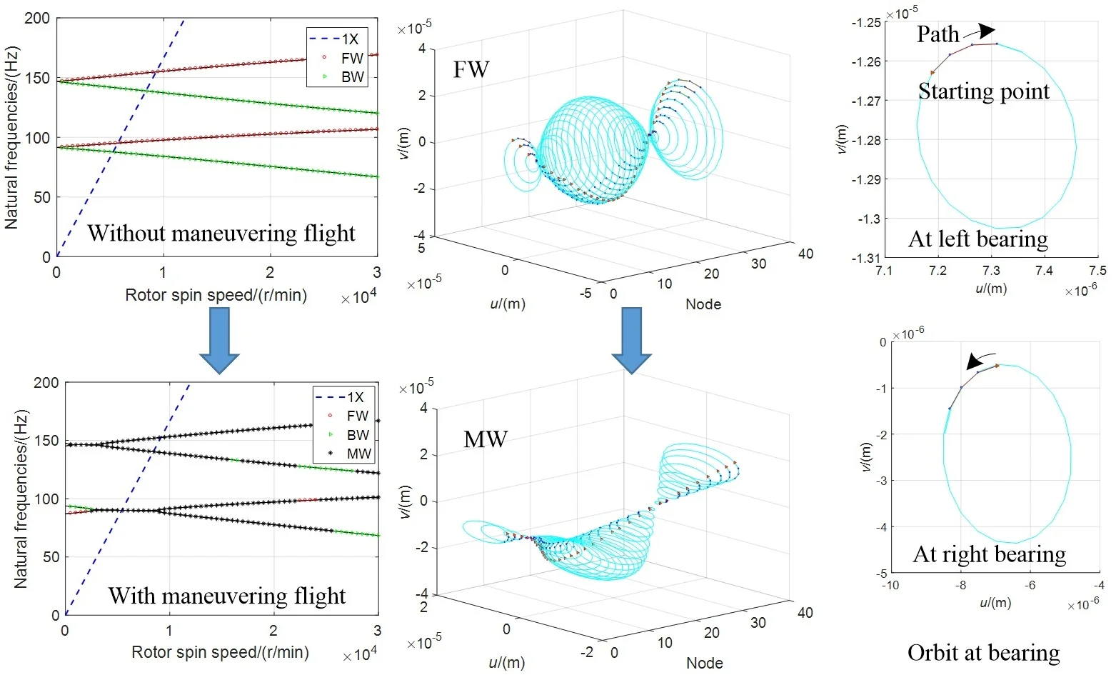
The effect of maneuvering flight on the critical speeds and their whirl directions are shown in Fig. 2, where 1X represents the rotation speed, BW, FW, and MW represent the backward, forward, and mixed whirl respectively. From the Campbell diagram, we can see that, the forward and backward whirl occur under the ground test conditions of the engine rotor that without considering the maneuvering flight, but the mixed whirl does not. When considering the maneuvering flight, that is, under air cruising conditions, the rotor system is mainly characterized by hybrid whirl, the backward and forward whirl only appear in some small ranges of the rotation speed. The biggest difference appears at the range of 3500 r/min to 9000 r/min, the two natural frequencies of forward and backward whirl during non-maneuvering flight almost overlap in certain low frequency range, and the rotor system has a mixed whirl instead of both the forward and backward whirl modes.
Table 3 gives the impact of maneuvering flight on the critical speeds of the rotor system. Compared to non-maneuvering flight, the most change about the critical speeds of the rotor system is at the first order critical speed in the forward whirl mode (critical speed number 2 in Table 3), where 5.36 % smaller than the original speed. Furthermore, at speeds above 9000r/min, the natural frequencies of maneuvering flight exhibit a clear bifurcation, which is similar to the forward and backward whirl frequency lines of non-maneuvering flight. Noting that, the forward or backward whirl mode may be occurred within some small frequency ranges that is similar to the non-maneuvering flight condition and has the same properties, which the natural frequency increasing with rotational speed during forward whirl mode and decreasing during backward whirl.
Fig. 1Rotor structure
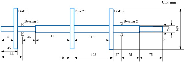
Table 1Parameters of disks
Mass (kg) | Polar moment of inertia (kg·m2) | Diameter moment of inertia (kg·m2) | Unbalance amount (10-6 kg·m) | Unbalance phase (°) | |
Disk 1 | 0.5257 | 0.0004 | 0.0002 | 6.35 | 280 |
Disk 2 | 0.5257 | 0.0004 | 0.0002 | 6.35 | 60 |
Disk 3 | 0.5257 | 0.0004 | 0.0002 | 6.35 | 316 |
Table 2Parameters of maneuvering flight
Direction about Northeast earth’s coordinate system | Longitude | Lateral | Normal |
Turning radius (m) | 5 | 500 | 100 |
Angular velocity (rad/s) | 0.01 | 0.7 | 0.5 |
Maneuvering overload (m/s2) | 1 | 20 | 40 |
Table 3Effect of maneuvering flight on critical speeds
Critical speed number | Without maneuvering flight (r/min) | Maneuvering fight (r/min) | Comparison (%) | ||
Velocity | Direction | Velocity | Direction | ||
1 | 5260.4 | BW | 5402.8 | MW | 2.71 |
2 | 5709.2 | FW | 5403.1 | MW | –5.36 |
3 | 8330.7 | BW | 8419.2 | MW | 1.06 |
4 | 9283.5 | FW | 9149.7 | MW | –1.44 |
To further research the effect of mixed whirl caused by maneuvering flight on rotor vibration response, we investigate the amplitude, shape, and whirl direction of rotor orbits, the involved parameters of unbalance for calculation are shown in Table 1.
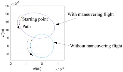
For illustrating the direction easily and visually, we define the spin direction of an orbit by Fig. 3. In this figure, a colored triangle symbol “” is as the starting point of an orbit’s direction, and three adjacent smaller circles “” as the next moving path of the orbit at its nodes. We call this type of orbit in Fig. 3 as orbit direction graph. It can be seen that maneuvering flight not only changes the amplitude of the orbit at a single speed (5402 r/min), but also changes the orbit shape from a circular shape during non-maneuvering flight to a slanted ellipse with some inclined angle.
Fig. 2The Campbell diagram
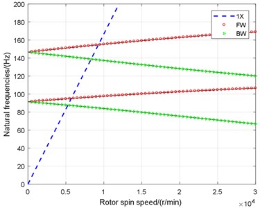
b) Without maneuvering flight
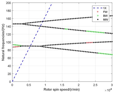
a) With maneuvering flight
Fig. 3Orbits and their directions at 5402 r/min
The whirl orbits and their directions against spin speed are shown in Fig. 4. It can be seen that, maneuvering flight hardly affects the trend of the rotor vibration amplitudes against speed, nor does it change the direction of the rotor centroid motion (for example, both of non-maneuvering flight and maneuvering flight are turning direction between 20000 r/min and 22000 r/min). However, the amplitude range of the rotor in the y direction of the body coordinate system becomes larger than on the non-maneuvering flight condition.
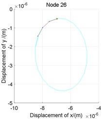
The effects to the orbit’s shape in the mixed whirl modes show in Fig. 5, where the rotor is divided into 36 nodes and numbered as nodes 1 to 36 from left to right in turn, noting that, the node 5 and node 26 are at the left and right bearing respectively. The orbits of the rotor under four cases of speed at 5260 r/min, 5709 r/min, 5402 r/min, and 24000 r/min are calculated, where the first two are in non-maneuvering but the last two are in maneuvering state, which represent BW, FW, MW, and pending directions of whirl. The first two cases are the critical speeds of the rotor in non-maneuvering and the third case are under maneuvering flight, we can determine their whirl directions from the Campbell diagram. The fourth case is complex, from the Campbell diagram, we know the speed in this case are not a critical speed, and all of the mixed, forward and backward direction appear at the speed, the whirl direction of the rotor subjected to unbalanced mass and maneuvering flight cannot be determined by the Campbell diagram and is pending. To distinguish the shape characteristics as well as to determine the direction of case 4, we need to analyze Fig. 5 (a)-(d) carefully.
For analyzing the whirl vibration from simplicity to difficulty, we analyze Case 1 (Fig. 5(a)) and Case 2 (Fig. 5(b)) firstly. Regardless of the forward and backward whirl, the vibration mode shapes of both are circular motion around the shaft axis during non-maneuvering flight, and all nodes synchronize to pass through the balance position in the direction as well as in the direction.
Analyze the mixed whirl mode of case 3 (Fig. 5(c)) furtherly. Combined with the oblique ellipse phenomenon of orbit on the maneuvering flight in Fig. 4, it can be seen from Fig. 5 that the vibrational shape of the rotor during mixed whirl is relatively complex. Some nodes, such as nodes 1-5, always appear centroid dynamic eccentricity, and do not pass through their balance position during the whole vibration procession. The eccentricity amplitude of the cross-sectional center in the rotor system continuously changes with the node position, the centroid position of the rotor shaft can be positive or negative while subjected to the effect of the dynamic eccentricity.
Fig. 4Orbits against spin speed for node at Bearing 2
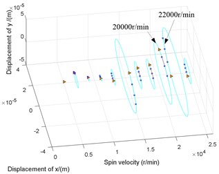
a) Without maneuvering flight
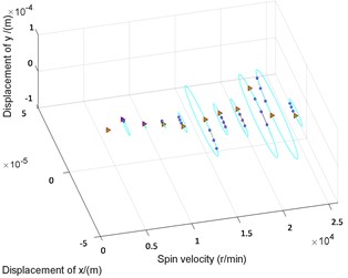
b) With maneuvering flight
Fig. 5Orbits against node
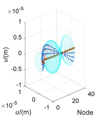
a) Case 1
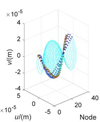
b) Case 2
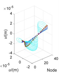
c) Case 3
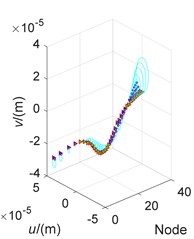
d) Case 4
Fig. 6The orbits of nodes on bearings at 24000 r/min
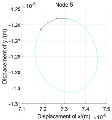
a) Left bearing
b) Right bearing
Analyze now the pending whirl form of case 4 in the end. Observing Fig. 5(d), we can see that the orbits of node 1 and node 36 rotate in opposite direction. Therefore, according to the identification method to whirl direction, case 4 undergoes a mixed whirl due to unbalanced excitation and the maneuvering flight conditions described in the Table 3. In this whirl pattern, even if the interested or operating speed is non-critical, the displacement amplitude of the rotor node may be greater than which at some critical speeds (the displacement amplitude here refers to the combination of the eccentricity amplitude of the shape center and the vibration amplitude).
The orbits of nodes on bearings are shown in Fig. 6, the whirl directions of both bearing are different, indicating once again that case 4 is a mixed whirl pattern, furthermore, the inclination angles of orbits are also different, which can explain theoretically that the actual contact angles of bearings in a rotor system may be different under maneuvering flight and variable with the rotor speed.
4. Conclusions
This paper provides identification method for whirl directions of a rotor system. For the forward, backward and mixed whirls, the effects of maneuvering flight on the critical speed and orbit direction of a single rotor system are analyzed. Maneuvering flight changes the characteristics of the Campbell diagram, both the original backward and forward critical speeds in the same order maybe overlap to one mixed whirl critical speed. Maneuvering flight results in dynamic eccentricity of the rotor shaft centroid position, which can be positive or negative. Even if the rotor operates at a non-critical speed, the displacement amplitude of the rotor centroid may be greater than that at the critical speed. The orbit direction graph can be used to identify the mixed whirl, and the whirl directions of orbits on bearings maybe different under maneuvering flight.
References
-
M. A. Al-Shudeifat, “New backward whirl phenomena in intact and cracked rotor systems,” Journal of Sound and Vibration, Vol. 443, pp. 124–138, Mar. 2019, https://doi.org/10.1016/j.jsv.2018.11.038
-
M. A. Al-Shudeifat, “Impact of non-synchronous whirl on post-resonance backward whirl in vertical cracked rotors,” Journal of Sound and Vibration, Vol. 520, p. 116605, Mar. 2022, https://doi.org/10.1016/j.jsv.2021.116605
-
Y. Kang, S. Cao, Y. Hou, and N. Chen, “Analysis of backward whirling characteristics of a dual-rotor system caused by unbalance,” Measurement, Vol. 203, p. 111982, Nov. 2022, https://doi.org/10.1016/j.measurement.2022.111982
-
M. I. Friswell, J. E. T. Penny, S. D. Garvey, and A. W. Lees, Dynamic of Rotating Machines. New York: Cambridge University Press, 2010, pp. 119–120.
-
N. Zheng, M. Chen, G. Luo, and Z. Ye, “Coupled lateral and torsional vibration of rub-impact rotor during hovering flight,” Shock and Vibration, Vol. 2021, pp. 1–25, Oct. 2021, https://doi.org/10.1155/2021/4077556
-
Y. Jin, Z. Sun, Y. Song, X. Lin, X. Niu, and J. Ding, “Mission segment division of the whole aeroengine loading spectrum based on flight actions,” Chinese Journal of Aeronautics, Vol. 35, No. 2, pp. 164–174, Feb. 2022, https://doi.org/10.1016/j.cja.2021.06.015
-
N. Zheng, M.-L. Chen, G.-H. Luo, and Z.-F. Ye, “Dynamic behavior analysis of intermediate bearing-squeeze film dampers-rotor system under constant maneuvering overload,” Shock and Vibration, Vol. 2021, pp. 1–24, Apr. 2021, https://doi.org/10.1155/2021/5512409
About this article

The research is funded by National Science and Technology Major Project, Grant number J2019-IV-004-0071.
The datasets generated during and/or analyzed during the current study are available from the corresponding author on reasonable request.
The authors declare that they have no conflict of interest.
