Abstract
Dynamic model of bearing-rotor system is developed considering the collision effects between the cage and its guiding land. The modal characteristic and vibration response are studied with the fourth-order Runge-Kutta method. It is demonstrated that the cage whirling motion arising as a result of collision with the guiding land would induce abnormal frequency components in the system’s response including the multiple frequency as well as the modulation between the speed frequency and the natural frequency. Additionally, cage whirling motion and rotor vibration become severe when the rotor rotates around its pitching-mode critical speed. It is shown that the amplitudes of abnormal frequencies can be decreased by reducing rotor unbalance in a given range.
1. Introduction
Rolling bearing is widely used in rotating machinery, and its performance directly affects the rotor dynamic response. Bearing cage is significant component to separate and guide elements. Cage whirling motion due to destructive collision force between the cage and rolling elements or race land can give rise to destruction of bearing structure and abnormal vibration of rotor system. Fig. 1 shows one typical case of bearing structure failure, and cage spin frequency modulated to rotor rotation frequency , producing sideband signals ±, which might generate great harm to the security of whole equipment. Therefore, it is critical to study the mechanism of cage whirling motion and its influence on the dynamic characteristic of bearing-rotor system.
Fig. 1Typical case of bearing damage and rotor vibration problem related to cage whirling motion
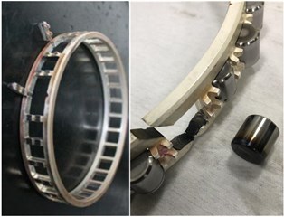
a) Cage fracture and element wearing
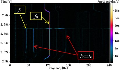
b) Frequency modulation in rotor vibration signal
In the past decades, many researches have been conducted about the dynamic characteristic of bearing cage. Kingsbury [1] firstly put forward the mechanism that the amplitude of cage whirling motion would varies at a particular frequency because of element loading inequality and periodically changing sides within their pockets. Walters [2] numerically integrated the bearing motion equations with a fourth order Runge-Kutta scheme, and the results demonstrated that the cage whirling direction would be different as the cage guiding condition was changed. After that, abundant works have been done about dynamic modeling, parameters effects and motion stability of bearing cages [3]-[6]. However, the influence of rotor dynamic response on the cage motion are hardly considered. On the other hand, dynamic analysis of bearing-rotor system is the hotspot in rotating machinery engineering, but the scholars are mainly focused on the nonlinear stiffness and rotor instability caused by bearing clearance or varying compliance [7]-[9], ignoring the effect of cage motion or excitation. In recent years, some studies on the dynamic interaction between bearing cage and rotor system have been conducted. Chen [10] investigated the effects of rotor vibration on the cage dynamic performance. But the mechanism of cage whirling motion and its influence on the rotor dynamic remains unclear.
In this paper, a dynamic model for high-speed bearing-rotor system considering cage whirling motion and the cage collision with its guiding land is proposed. On the basis, the cage motion characteristic and the frequency components of the rotor response are studied in order to investigate the dynamic coupling effects between rotor and bearing cage.
2. Dynamic model of bearing-rotor system
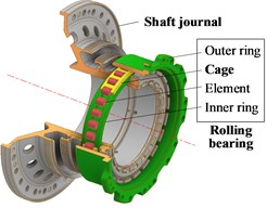
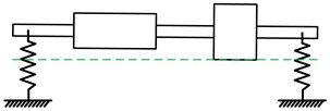
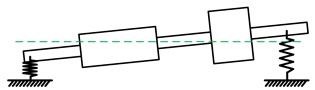
The structure of typical bearing-rotor system supported by fulcrums is shown in Fig. 2. , , (1, 2) are respectively supporting stiffness, damping coefficient and distance to the centroid of two fulcrums. In order to simplify the question, only the effect the rear bearing is investigated, as shown in Fig. 3, and the interface of inner ring and rotor journal is considered totally bounded.
Fig. 2Structural sketch of typical bearing-rotor system
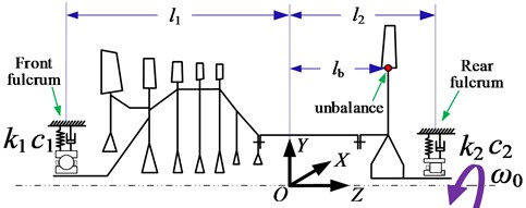
Fig. 3Structural diagram of the rolling bearing at the rear fulcrum
2.1. Dynamic differential equations of the rotor system
Assuming the rotor is rigid, the dynamic equations of the rotor system are written in Eq. (1):
where , , are respectively the rotor’s mass, polar and diameter moment of inertia; , are the rotor unbalance and its eccentricity, which is considered located at the rear half; is the distance between the centroid to the unbalance; is the angular velocity; , are bearing force components in and direction at the rear fulcrum.
2.2. Bearing forces considering cage collision with guiding land
Plenty of researches have been conducted to describe the bearing forces and in Eq. (1). Based on the bearing dynamic model developed in [11] and [12], this article further considers the effects of cage whirling motion and cage collision with its guiding land. The forces acting on cage are shown in Fig. 4, and the dynamic differential equations of cage are established as Eq. (2).
In Eq. (2), is the number of elements; is the mass of cage; represents moment inertias of cage on different directions; and are the skewing angular and position angles;, are respectively the contact forces between cage and element in normal and tangential directions; , are torques due to the cage skewing and the force maldistribution. , are respectively the lubricating oil resistances:
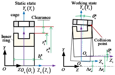
As shown in Fig. 5, there is an initial clearance () between the cage and its guiding land at static state, and the clearance varies () during the working process due to the skewing and procession motion of the cage and inner ring, which is expressed as Eq. (3):
where , are respectively the radius of cage and inner ring at the guiding area; is the half width of the guiding land in direction. , are the procession radius and skewing angle.
The collision between cage and inner ring occurs when . The normal and tangential component of the collision force respectively are:
where is the stiffness characteristic of the cage-land contact, and is the friction coefficient.
Fig. 4Schematic diagram of the forces acting on the cage
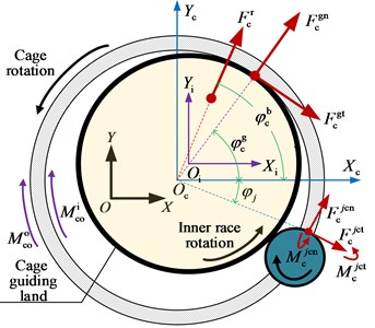
Fig. 5Schematic diagram of the collision effect between the cage and its guiding land
The dynamic model of the whole bearing-rotor system consists of the rotor model part (Eq. (1)) and the bearing model part, including the bearing forces model (Eq. (2)). These two parts are assembled with the equilibriums of the inner ring, which is fixed on and keeps the same displacement with the rotor shaft. The force balance equations for the inner ring are:
where , are respectively the normal and tangential force between the element and the outer raceway, and , are torques due to the element skewing and the force maldistribution.
2.3. Calculation procedure of the dynamic model
The basic steps of the calculation procedure for dynamic equations of the whole bearing-rotor system are listed as follow:
1) Input the structural parameters and working conditions (including rotation speed, preload) of the system, and start the quasi-static analysis with Newton-Raphson method to acquire the initial displacement/velocity state.
2) Calculate the interaction forces/toques on the basis of the dynamic models, and acquire the acceleration state of the whole system.
3 Conduct time integration calculation by the four order Runge-Kutta method. Reduce the time increment if the truncation error exceeds the allowance. Otherwise, update the displacement/velocity state for the next timestep until the time ending.
3. Results and discussion
Based on the above dynamic model and calculation method, modal characteristics and dynamic response of the bearing-rotor system is analyzed considering the effect of cage whirling motion. The key parameters of the system are shown in Table 1.
Table 1Structural parameters of the bearing-rotor system
Rotor parameters | |||
Rotor mass | 200 kg | Centroid distance to unbalance | 300 mm |
Rotor diameter rotary inertia | 20 kg∙m2 | Rotor unbalance | 100 g |
Unbalance eccentricity | 10 mm | Centroid distance to unbalance | 300 mm |
Front supporting stiffness | 2.5e7 Nm | Rear supporting stiffness | 4e7 Nm |
Centroid distance to front fulcrums | 600 mm | Centroid distance to rear fulcrums | 450 mm |
Bearing parameters | |||
Number of the elements | 16 | Radial internal clearance | 0.04 m |
Cage mass | 0.2704 kg | Cage unbalance | 10 g∙mm |
Cage pocket clearance | 0.1 mm | Cage guiding clearance | 0.04 mm |
3.1. Modal characteristics of the simple supported rotor system
Eigenvalue of Eq. (1) is obtained given equals to zero, and modal characteristics of the simple supported rotor system are analyzed. Campbell diagram and mode diagrams under the critical speed of the rotor system are shown in Fig. 6 and Fig. 7 respectively. The first order of the rotor modal is translational mode whose critical speed is 5400 rpm, and the second order is pitching mode whose critical speed is 10711 rpm.
3.2. Dynamic response of the bearing-rotor system
On the basis of modal characteristics analysis, four typical speeds are picked up including 2 krpm, 5 krpm, 10 krpm and 20 krpm, corresponding four typical rotating states: far below the critical speed, near to the translational critical speed, near to the pitching critical speed and far above the critical speed. Fig. 8 shows the dynamic responses of the bearing-rotor system under these four typical speeds.
Fig. 6Campbell diagram of the simple supported rotor system
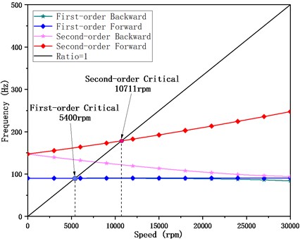
Fig. 7Mode diagrams of the simple supported rotor system under critical speeds
a) The first order, translational mode
b) The second order, pitching mode
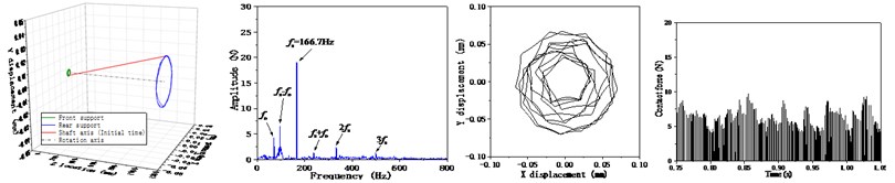
Fig. 8Dynamic responses of the bearing-rotor system under different speed
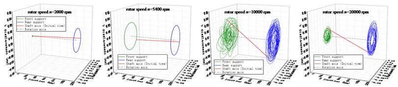
a) Center orbits at the fulcrums and the shaft axis of the rotor
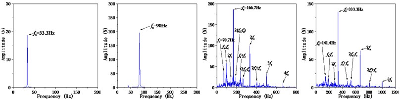
b) Frequency spectrums of the rear fulcrum load response
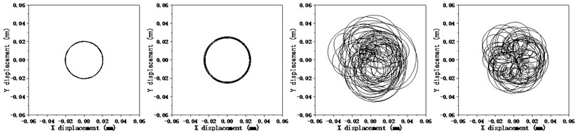
c) Center orbit of the cage
The results show that the rotor rotates under the translational mode shape at 2 krpm and 5 krpm, and rotating speed frequency is the only component in the spectrums of fulcrum load response. The cage center orbits are both circular with a similar radius. However, the load response of the rear fulcrum is higher at the 5 krpm as the rotor system is near to the resonance range.
The pitching mode shape of the rotor system is observed at the speed of 10 krpm and 20 krpm, and the frequency components are much more complicate, including the rotor rotatory speed , the cage rotatory speed , and their multiple frequencies , , , … and the modulation frequencies, for example, , and so on. The cage center orbits no longer keep circular, and there are severe collisions between the cage and its guiding land, leading to the cage whirling motion. The results exhibit the coupling effects between the rotor and the bearing cage when the rotor is rotating under the pitching mode.
3.3. Effects of the rotor unbalance on the dynamic response
Additional conditions of different rotor unbalance (20 g, 200 g) are considered and the dynamic responses of the bearing-rotor system are analyzed, as shown in Fig. 9. The rotor pitching angle and the rear fulcrum load response both increase when adding the rotor unbalance. However, the amplitudes at the modulation frequencies are found to be lower than the 100 g unbalance condition. When the rotor unbalance is 20 g, the response of whole system is at a lower level, and the collision of the cage is weaker. When it comes to the 200 g condition, rotor’s centrifugal effect is too strong, and the cage is forced to whirling on the rotor’s orbit, which also leading to the reduction of the cage collision effect and the components of modulation frequencies in the response signal.
Fig. 9Effects of the rotor unbalance on the dynamic response of the system
a) Rotor unbalance = 20 g
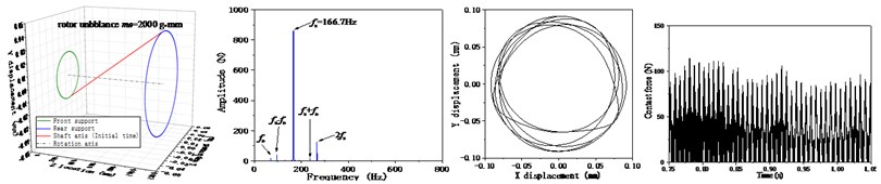
b) Rotor unbalance = 200 g
4. Conclusions
Through the analysis, the conclusions can be drawn as follow:
1) The influence of the cage whirling motion should be considered during the dynamic response analysis of the bearing-rotor system, which can cause abnormal vibration of the rotor system, inducing the multiple frequencies and modulation frequencies components in the system response.
2) The cage whirling motion is more easily induced when the rotor rotates around its pitching mode critical speed, as the skewing of the shaft and the inner ring exacerbates the collision between the cage and its guiding land.
3) The abnormal vibration of the bearing-rotor system can be suppressed by controlling the rotor unbalance, which essentially decreases the shaft pitching angle and the cage-guiding land collision effects.
References
-
E. P. Kingsbury, “Torque variations in instrument ball bearings,” ASLE Transactions, Vol. 8, No. 4, pp. 435–441, Jan. 1965, https://doi.org/10.1080/05698196508972113
-
C. T. Walters, “The dynamics of ball bearings,” Journal of Lubrication Technology, Vol. 93, No. 1, pp. 1–10, Jan. 1971, https://doi.org/10.1115/1.3451516
-
C. R. Meeks and K. O. Ng, “The dynamics of ball separators in ball bearings-part i: analysis,” ASLE Transactions, Vol. 28, No. 3, pp. 277–287, Jan. 1985, https://doi.org/10.1080/05698198508981622
-
C. R. Meeks, “The dynamics of ball separators in ball bearings-part II: results of optimization study,” ASLE Transactions, Vol. 28, No. 3, pp. 288–295, Jan. 1985, https://doi.org/10.1080/05698198508981623
-
B. Choe, W. Kwak, D. Jeon, and Y. Lee, “Experimental study on dynamic behavior of ball bearing cage in cryogenic environments, Part Ⅱ: Effects of cage mass imbalance,” Mechanical Systems and Signal Processing, Vol. 116, No. 1, pp. 25–39, Feb. 2019, https://doi.org/10.1016/j.ymssp.2018.06.034
-
W. Liu, X. Zhang, S. Wang, Y. Zhang, and G. Wang, “Application of cage guided by combined action of outer race and balls in beating vibration reduction,” Journal of Vibration and Shock, Vol. 39, No. 21, pp. 24–33, 2020, https://doi.org/10.13465/j.cnki.jvs.2020.21.004
-
T. Yamamoto, “On critical speeds induced by ball bearings at lower rotating speeds,” Bulletin of JSME, Vol. 1, No. 3, pp. 240–244, 1958, https://doi.org/10.1299/jsme1958.1.240
-
C. S. Sunnersjö, “Rolling bearing vibrations: the effects of varying compliance, manufacturing tolerances and wear,” Aston University, 1976.
-
Y. Ma, T. He, D. Zhang, and J. Hong, “Imbalance response of rotor system with nonlinear bearing stiffness,” Journal of Aerospace Power, Vol. 29, No. 7, pp. 1528–1534, 2014, https://doi.org/10.13224/j.cnki.jasp.2014.07.003
-
S. Chen, R. Wang, X. Chen, J. Gu, and Z. Liu, “Analysis of dynamic coupling characteristics of high speed angular contact ball bearing-rigid rotor system under different working conditions,” Journal of Aerospace Power, Vol. 37, No. 2, pp. 344–355, 2022, https://doi.org/10.13224/j.cnki.jasp.20210082
-
S. Deng, Q. Jia, and J. Xue, Design Theory of Rolling Bearing. Beijing: Standards Press of China, 2014.
-
Y. Cui, S. Deng, H. Yang, W. Zhang, and R. Niu, “Effect of cage dynamic unbalance on the cage’s dynamic characteristics in high-speed cylindrical roller bearings,” Industrial Lubrication and Tribology, Vol. 71, No. 10, pp. 1125–1135, Dec. 2019, https://doi.org/10.1108/ilt-12-2018-0462
About this article

The research was funded by the National Natural Science Foundation of China (Grant No. 52075018) and National Science and Technology Major Project (Grant No. 2017-IV-0011-0048).
