Abstract
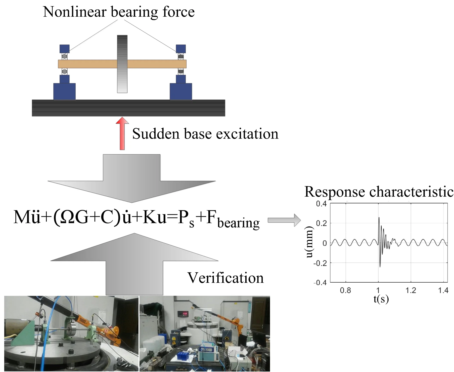
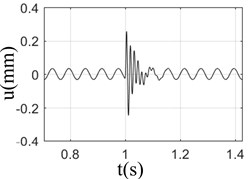
In this paper, the rotor system with nonlinear bearing force and base excitation load was modeled based on finite element method, and its response characteristic under the excitation of base load was studied. The results show that the response of the rotor is the superposition of the basic impulse response and the unbalanced response. The pulse excitation energy can be dispersed while the rotation speed and pulse frequency are close to each other. When the phase difference of unbalanced excitation is 180°, the response amplitude of rotor bearing system was the smallest. The correctness of the rotor bearing system model was verified by experiments.
Highlights
- A rotor-bearing system considering the sudden base excitation load was modeled based on the finite element method.
- The influence of rotational speeds, amplitude of pulse excitation and pulse width on the dynamic characteristics of the rotor-bearing system was researched.
- A response test was arranged and the simulation model was verified.
1. Introduction
In recent years, scholars have done a lot of research on the transient dynamic behavior of foundation under impact or earthquake excitation. Lee found that the transient response of the rotor is very sensitive to the impact duration [1, 2]. Gaganis studied the response of rotor bearing system under seismic excitation, and the method used is more accurate than the linear model [3]. Ji Jinzhao established the sliding bearing rotor system model under the impact of foundation by using the lumped mass method [4]. He Shaohua solved the problem that the average acceleration Newmark method could not solve the first-order differential equations in state space, and analyzed the stability of the method, which showed that it was unconditionally stable [5]. Chuan-Ju Li et al. did a research about the method for avoiding the damage of bearing in the engineering application [6]. Bediaga I. et al. found that the Hilbert Transform and Amplitude Modulation are the most effective traditional method for bearing fault detection and the faults in the static race are more easily detected than the ones in the moving race [7]. Huageng Luo et al. proposed synthesized synchronous sampling technology to detected damage at a much earlier stage [8]. However, few research took the base excitation load and nonlinear bearing force into consideration while modeling the rotor system. In this paper, a rotor system with the base excitation load and nonlinear bearing was modeled based on finite element method and was verified by the experiment.
2. Modeling of rotor-bearing system
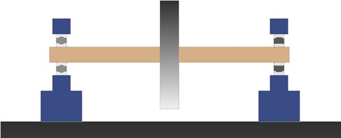
For the rotor bearing system shown in Fig. 1, the differential equation of rotor motion is shown in Eq. (1):
where, is the rotation angle velocity of the rotor, is the basic impulse excitation load vector of the rotor bearing system, , , , is the inertia matrix, damping matrix, gyroscope matrix and stiffness matrix of the system respectively, and is the nonlinear bearing force vector. There are different forms for . In this paper, the excitation modes of half sine were adopted, were obtained by Hertz contact theory. For Eq.(1), Newton Raphson method is used to solve the displacement and bearing stiffness in each sub step, and Newmark- method is used to solve the transient response of rotor bearing system under the action of basic impulse excitation.
Fig. 1Schematic diagram of rotor- bearing system under foundation excitation
3. Response analysis of rotor-bearing system under base load
In this paper, the effects of rotor speed, pulse amplitude, pulse width on the response of rotor bearing system were studied and analyzed. When the unbalance, pulse amplitude, pulse width and pulse form of the rotor bearing system are determined, the rotor speed was changed to obtain the response at different rotational speeds.
Fig. 2Response of rotor-bearing system with sudden high energy load at different speeds
a) 1000 rpm
b) 2000 rpm
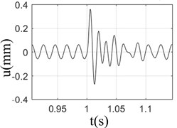
c) 3000 rpm
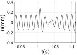
d) 4000 rpm
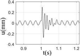
It can be seen from Fig. 2 that when the speed was 3000 rpm, the displacement response of the rotor was the largest; however, the response was almost the same at different speeds; At low speed (1000-2000 rpm), the change of rotor displacement caused by base load is large, and more damping cycles was needed to exhaust the impact energy and turn to stable operation; however, the damping cycles needs to be attenuated was less at high speeds (3000-4000 rpm), due to its large inertia and strong resistance to external load; Fig. 2 shows that under the action of base load, the rotor response is composed of unbalance response and sudden excitation response. If the unbalance response of rotor is larger, the damping effect of rotor itself would be weaker. The inertia of the rotor has a certain resistance to the impact of the foundation. However, that doesn’t meant that the higher rotation speed state is better than lower one, for the bearing damage would be caused by the higher rotation speed.
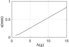
Under different pulse amplitude, the relationship between pulse amplitude and response amplitude is shown in Fig. 3. Fig. 3 shows that with the increase of pulse amplitude, the attenuation period of rotor increases gradually, and the relationship between the maximum amplitude of response and the load is basically linear.
Fig. 3The amplitude of pulse excitation vs displace response
Under the same pulse amplitude, the larger the pulse width, the higher the impulse and the lower the pulse frequency. The impulse and frequency are determined by the pulse width of the base suddenly applied high energy load.
The relationship between peak value and valley value of rotor bearing system under different pulse width is shown in Fig. 4.
Fig. 4Peak value vs pulse width and valley value vs pulse width
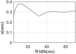
a) Peak value of response vs pulse width
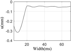
b) Valley value of response vs pulse width
Fig. 4 shows that during the pulse width increasing from 5 ms to 60 ms, the peak value and valley value reach the maximum value in 10 ms, and at 10 ms, the attenuation time is the longest and the damping period is the most. This shows that the rotor speed is the same as the pulse frequency corresponding to 10 ms, and the system resonates. Therefore, the frequency of the basic high-energy load can be calculated by the time of the carrier aircraft landing, and the speed of the engine rotor should avoid the frequency of the shock wave as far as possible, which can improve the safety of the carrier based aircraft when landing on the ship.
4. Response test and model verification of rotor bearing system under high energy load of foundation
In this paper, Jeffcott rotor test rig was used to verify the theoretical calculation; INV3018CT 24 bit high-precision data acquisition instrument of Beijing Dongfang vibration and noise technology research institute is used for data acquisition and analysis, and ES-50W-445 electric vibration test system of Suzhou Dongling vibration test instrument Co Ltd. was used to apply foundation load.
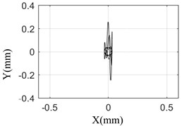
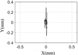
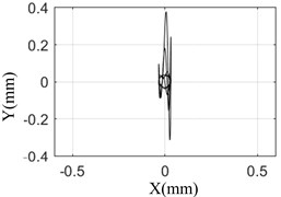
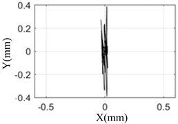
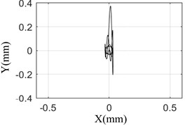
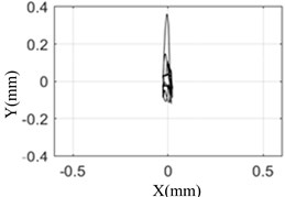
The amplitude and orbit of the rotor response are collected under different pulse width, and compared with the simulation results which was shown in the Fig. 7.
Fig. 7 shows that the test results are the same as the simulation results. When the pulse width is 10 ms, the response of the rotor is the largest and the axis orbit is the most complex. The rotor center orbit and response amplitude obtained by simulation and test are consistent with each other.
This shows that the model established in this paper can truly reflect the response of rotor bearing system under sudden high-energy load on the foundation. The conclusion based on the model is reliable.
Fig. 5Test rig
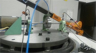
Fig. 6Measurement device
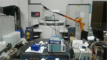
Fig. 7The comparison between simulation and test result under different pulse width
a) Simulation result (5 ms)
b) Test result (5 ms)
c) Simulation result (10 ms)
d) Test result (10 ms)
e) Simulation result (15 ms)
f) Simulation result (15 ms)
5. Conclusions
Based on the simulation and experimental results of this paper, the results show that the response of low speed rotor bearing system is greatly affected by high-energy load, while the response of high-speed rotor bearing system is less affected. the greater the pulse amplitude, the greater the response of rotor bearing system, and the longer the attenuation time. There is a linear relationship between the pulse amplitude and the response amplitude of rotor bearing system. The speed should avoid the frequency corresponding to the pulse width to avoid resonance.
References
-
Lee A. S., Kim B. O., Kim Y. A finite element transient response analysis method of a rotor-bearing system to base shock excitations using the state-space Newmark scheme and comparisons with experiments. Journal of Sound and Vibration, Vol. 297, Issues 3-5, 2006, p. 595-615.
-
Kim B. O., Lee A. S. A transient response analysis in the state-space applying the average velocity concept. Journal of Sound and Vibration, Vol. 281, Issues 3-5, 2005, p. 1023-1035.
-
Gaganis B. J., Zisimopoulos A. K., Nikolakopoulos P. G., Papadopoulos C. A. Modal analysis of rotor on piecewise linear journal bearings under seismic excitation. Journal of Vibration and Acoustics, Transactions of the ASME, Vol. 121, Issue 2, 1999, p. 190-196.
-
Ji Jinzhao, He Shaohua, Wu Xinyue, Wan Qiang The research on the impulse response of the rotor-bearing system. Marine Technology, Vol. 37, Issue 5, 2010, p. 16-19, (in Chinese).
-
He Shaohua, Wu Xinyue A shock simulation method for rotor systems-average velocity Newmark-Riccati transfer matrix technique. Chinese Journal of Applied Mechanics, Vol. 27, Issue 4, 2010, p. 823-829.
-
Chuan Ju Li, Yuan Gui D., Sha Sha N., et al. Research and treatment method of damage vibration of bearing problems of vibration sieve. Coal Mine Machinery, 2014, (in Chinese).
-
Bediaga I., Mendizabal X., Arnaiz A., et al. Ball bearing damage detection using traditional signal processing algorithms. Instrumentation and Measurement Magazine, Vol. 16, Issue 2, 2013, p. 20-25.
-
Huageng Luo, Hai Qiu, George Ghanime, et al. Synthesized synchronous sampling technique for differential bearing damage detection. Journal of Engineering for Gas Turbines and Power, Vol. 132, Issue 7, 2010, p. 072501.
About this article

National Science and Technology Major Project of China (Project No. 2017 IV 0006 0043).
