Abstract
Vibrations in rotating machinery are commonly the result of mechanical faults including mass unbalance, coupling misalignment, mechanical looseness etc. Rotating machinery with overhung rotors is very common in industries. Unbalanced rotor and misaligned shafts usually cause excessive machine vibration, generates large forces on bearings and thus reduces the machine life span and may lead to property loss and even loss of human life. Two-plane balancing of overhung rotors is one of the most challenging problem that maintenance engineers may encounter. As a prerequisite, successful diagnosis of unbalanced overhung rotor system must be performed. The vibration signatures of unbalanced overhung rotors with unknown initial conditions are different from those of the systems with centre hung rotors that has been studied in the present work. Experiments were carried out on a Machinery Fault Simulator-Lite (MFS-Lite) for both balanced and unbalanced rotor systems. The data were analysed using the Balance Quest software and efforts were focused on identifying the system characteristic signatures. Further, the results were verified through analytical methods and the results were found to be satisfactory.
1. Introduction
A small amount of unbalance weight in rotating system may have devastating effects as the system is operating with high speed or running near the critical speed. Therefore, extreme care must be taken in balancing high-speed rotating system to avoid any potential damages. Overhung rotors are commonly used in fluid turbo-machinery, such as pumps, propellers and fans. Balancing is the process of attempting to improve the mass distribution of a body so that it rotates in its bearings without unbalanced centrifugal forces. It is important to recognize that most balancing operations are performed below the first critical speed. To balance above the first critical requires different techniques and may be supported by another type of software. Balancing is the procedure of measuring vibration and adding or removing weight to adjust the mass distribution. The final goal is to reduce vibration level. Mass balancing is only one remedial action for excessive vibrations from machines.
Several review papers in the area of rotor balancing have been published over the past years that includes Parkinson [1] who reviewed in his book the state of the art on unbalance response and balancing of rigid and flexible rotor, he has also included a description of experimental work and a comparison between the different balancing methods. Van de Vegte [2] proposed the idea of balancing without interrupting operation, but that work concentrated on theoretical problems associated with the possibility of closed loop automatic control. Srinivasan [3] has done comprehensive experimental studies in the rotating machinery for the faults like misalignment (parallel misalignment from 0.025 mm to 0.65 mm, angular misalignment from 0.02 degree to 0.6 degree), unbalance (105.06 gm-cm to 491.98 gm-cm), mechanical looseness, rotor rub, bearing clearance (from 0.02 to 0.08 mm) and crack (transverse cracks of width 0.75 mm and depth ranging from 1.02 to 4.02 mm at the mid span of the shaft). Pandey and Nakra [4] provide a valuable information regarding symptoms of machinery failure which in practice may avoid costly break downs. The fault like parallel misalignment, angular misalignment, combined parallel and angular misalignment and unbalance have been simulated. In all cases amplitudes are higher at NDE (Non-Drive End) and lesser at DE (Drive End). The amplitude is higher in axial direction in both the ends and increased whenever misalignment increased. Vyas and Satish [5] have carried out experimental studies to generate data and discussed the development of neural network simulator for prediction of faults like mass unbalance, bearing cap looseness, play in spider coupling and rotor with both mass unbalance and misalignment and health machine network. The test data were generated on a laboratory rotor rig which consist of a 10 mm diameter shaft carrying a centrally located steel disk (0.5 kg mass) and supported in identical rolling element bearing (6200 SKF ball bearing) at the two bearing and driven by 50-Watt, 230 Volt AC/DC electric motor through a flexible spider coupling. Fault simulated were: Mass unbalance, Loose Bearing cap & Misalignment and both mass unbalance & misalignment.
2. Experimental setup for balancing of rotor
The experimental setup used in this study is shown in Fig. 1. This apparatus is driven by a 3-HP induction motor with a speed range between 20 and 3000 rpm. The shaft rotation speed can be controlled by a speed controller.
Fig. 1Experimental setup for two plane rotor system
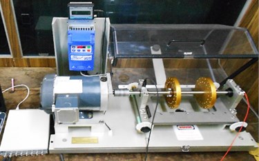
An optical sensor is used for shaft-speed measurement. A flexible coupling is utilized to damp out the high-frequency vibration that was generated by the motor. Two rolling-element bearings are fitted in the solid housings. Accelerometers are mounted on the housing of the tested bearing to measure the vibration signals along two directions. Based on the structure properties, the signal that was vertically measured is utilized for analysis in this study, whereas the information from the signal that was horizontally measured is used for verification. Data were acquired using Spectra PAD data acquisition board at 51.2 kHz sampling rate for about 32 seconds.
Vibrations from the inboard bearing and outboard bearings were measured in vertical directions using accelerometers. Tachometer in the MFS is used to measure the exact shaft speed. The tests are taken with the Aluminium Rotor. The two conditions of rotor are considered namely; 1. Centerhung rotor and 2. Overhung rotor.
3. Balancing using BQ software
In two plane rotor system, the test was carried out at 15 Hz for centrehung loading. The Correction Weight for balancing the rotor are obtained for both the cases which are as follows:
For Centrehung loading: 1.214∠122.72 gm, 10.476∠205.82 gm,
For Overhung loading: 6.1268∠298.79 gm, 5.3770∠148.53 gm.
The sample reading obtained from BQ Software for 15 Hz centrehung loading are.
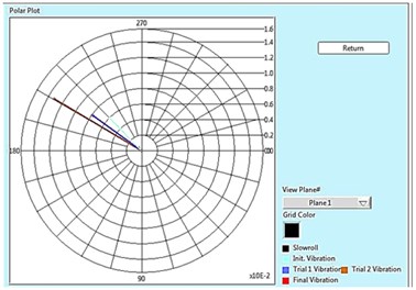
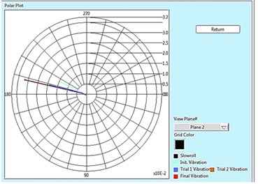
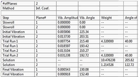
Fig. 2Polar plot for plane 1, 2 and Tabular result for 15 Hz
a)
b)
c)
Fig. 3(a)-(d) shows the Spectrum analysis (i.e. Amplitude Vs Frequency) of two rotor system at 15 Hz (900 rpm). The amplitudes are measured in mm whereas the frequency in Hz. Fig. 3(a) shows the initial vibration at DE/Near End and NDE/Far End. Fig. 3(b) shows the trial vibration 1 at DE and NDE. Fig. 3(c) shows the trial vibration 2 at DE and NDE. Fig. 3(d) shows the Final vibration at DE and NDE respectively, after the removal of unbalance in the rotor.
Fig. 2 shows the polar plot of two rotor system at 15 Hz (900 rpm) for both the plane i.e. plane 1 and plane 2. Polar plot shows in initial unbalance response present in the rotor, response with trial weight of 4.32 gm placed at plane 1, response with trial weight of 4.32 gm placed at plane 2 and the final vibration after the removal of unbalance in the rotor, and also shows the complete result of balancing in tabular form in which initial unbalance in near and far plane are 5.806 µm and 13.730 µm respectively. After placing trial weight of 4.32 gm in near plane (Plane 1), we got the vibration amplitude 7.754 µm in near plane and 18.597 µm at far plane. Similarly, after placing trial weight of 4.32 gm in far plane (Plane 2), we got the vibration amplitude 13.104 µm in near plane and 31.238 µm at far plane.
Using the data recorded from the previous steps, BQ Software calculates the correction weight size and location i.e. 10.47 gm at ∠205.82 in plane 1 and 1.21 gm at ∠122.7 in plane 2. By placing these weights in the desired location, we got the final vibration amplitude that is equal to 0.543 µm in near plane and 0.918 µm at far plane, which is almost negligible in comparison to original response as shown in Fig. 3(d).
Fig. 3Balancing of single plane rotors at 15 Hz (900 rpm)
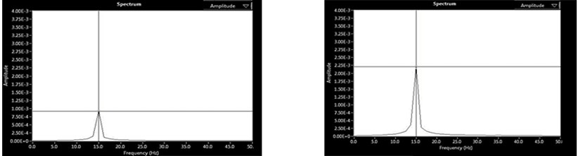
a) Initial vibration at DE and NDE
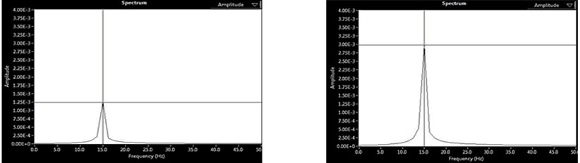
b) Trial 1 vibration at DE and NDE
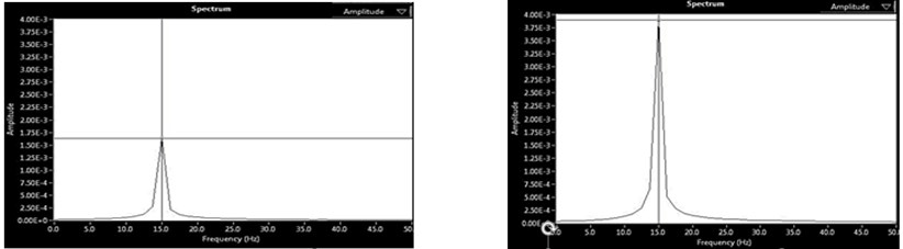
c) Trial 2 vibration at DE and NDE
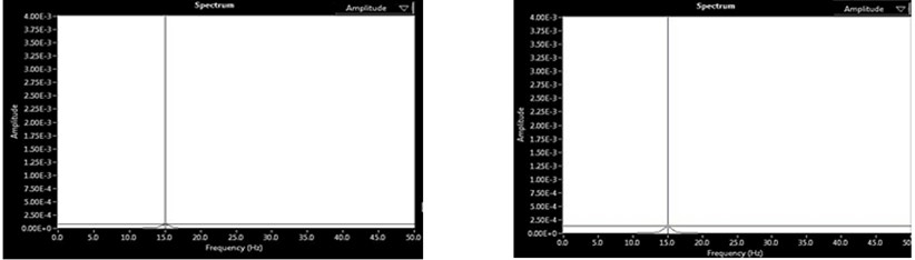
d) Final vibration at DE and NDE
4. Balancing using influence coefficient method
We have validated BQ results obtained above with the Analytical Method. i.e. Influence coefficient or Vector Method, where the role of phase is very important point of consideration.
Note: In BQ calculations, the phase is done as phase-lead convention and our weight location is defined as “angle in anti-rotating direction from reflective tape/key way”, which is a phase lag convention. And that’s why we have to convert it into phase-lead by using “360 minus weight spot” or Converting the trial weight location to phase lead by simply multiplying its angle by (–1), do the calculations & convert the correction weight back into phase lag by multiplying its angle by (–1) [6].
So, it’s all about which direction to count the angle, and as long as we keep the phase convention consistent in the calculation, we will get the correct answer.
The sample calculation for two plane Centerhung [7, 8] at 15 Hz, is mention below.
The initial vibration readings obtained on a rigid-body rotor are: 5.806∠225.34 µm and 13.73∠203.51 µm.
A trial balance weight of 4.32 gm is placed at a relative phase angle of 40°. The resulting vibration at near plane and far plane due to the placement of the trial weight at near plane are: 7.754∠215.48 µm and 18.597∠193.42 µm
The first balance trial weight is removed, and a trial weight of 4.32 gm is placed at a relative phase angle of 40° at far plane. The resulting vibration readings are: 13.104∠210.27 µm and 31.238∠192.72 µm.
For calculation in phase lag, we convert all the phase lead angle by multiplying “–1”.
5.80∠–225.34 µm, 13.73∠–203.51 µm, 7.75∠–215.48 µm,
13.10∠–210.27 µm, 18.59∠–193.42µm, 31.23∠–192.72 µm.
The influence coefficients at near and far plane caused by the trial weight placed at near plane are given by:
The influence coefficients at near and far plane caused by the trial weight placed at far plane are given by:
Balance correction:
We have done the sample calculation for 15 Hz in phase lag. To check the correctness of our experimental result, that is obtained from BQ Software. We have compared these results for two planes (Centerhung) from Analytical Results which is calculated from Influence Coefficient Method and has been shown in Table. 2. Further, these results have been found to be in very good agreement with each other.
Table 2Comparison of correction weight for two plane balancing
Speed (Hz) | Correction weight (gm) | |||
BQ software | Influence coefficient method | |||
Far plane | Near plane | Far plane | Near plane | |
15 (Centerhung) | 1.214526∠122.72 | 10.476238∠205.82 | 1.216∠122.48 | 10.503∠205.78 |
15 (Overhung) | 6.126859∠298.79 | 5.377068∠148.53 | 6.11∠298.752 | 5.365∠149.54 |
5. Conclusions
The conventional diagnosis method to diagnose faults in the rolling element bearing is not applicable for a rotor bearing system when the rotor operates at low/slow speed. The Experimental Results for Single Plane and Two Plane Centerhung and Overhung rotor conditions were carried out with different operation speed, different unbalance type and different unbalance weight. This has been shown by Analytical Method i.e. (Influence Coefficient Method) in order to check the correctness of the results. The results have been found to be in very close agreement with each other, which proves the correctness and robustness of the Experiment using MFS-Lite. The present study can also be used for online condition monitoring of rotor bearing system.
Experimental results of present study clearly indicate that Rotating system with overhung rotors, the existence of unbalance is closely related to two important signatures: the 1X radial force/acceleration spectrum magnitude, and more significantly and strongly, related to outboard bearing (the one close to the overhung rotor) 1X axial acceleration spectrum magnitude.
The bearing forces, and thus the sensitivity to unbalance, is proportional to the square of speed of rotation. Therefore, when more sensitivity required, higher balancing speed is used. Proper trial weight (TW) selection is important because a weight that is too light may not provide an adequate response for calculating correction weights and their placement. A trial weight that is too large may wreck the machine. Trial weights should adhere to the 30/30 rule [9] that says change the phase by 30 degrees or the amplitude by at least 30 percent. Experimental results have confirmed some observation from published literature that the fault like parallel misalignment, angular misalignment, combined parallel and angular misalignment and unbalance, in all cases amplitudes are higher at NDE and lesser at DE [4].
References
-
Parkinson A. G. Balancing of rotating machinery. Proceedings of the Institution of Mechanical Engineers, Part C: Journal of Mechanical Engineering Science, Vol. 205, Issue 1, 1991, p. 53-66.
-
Van De Vegte Continuous automatic balancing of rotating systems. The Journal of Mechanical Engineering Science, Vol. 6, Issue 3, 1964, p. 264-269.
-
Srinivasan K. S. Fault Diagnosis in Rotating Machines Using Vibration Monitoring and Artificial Neural Network. Ph.D. Thesis, Delhi, 2002.
-
Pandey S., Nakra B. C. Vibration Monitoring of a rotor system using RMS acceleration. International Journal of Engineering Science and Technology, Vol. 3, Issue 4, 2011, p. 2559-2572.
-
Vyas N. S., Satish Kumar D. Artificial neural network design for the fault identification in a rotor bearing system. Mechanism and Machine Theory, Vol. 36, 2001, p. 157-175.
-
Technotes. Spectra Quest Inc., 2012.
-
Eisenmann R. C. Machinery Malfunction Diagnosis and Correction: Vibration Analysis and Troubleshooting for the Process Industries. Prentice Hall, 1997.
-
Li Eric, Ganeriwala Suri Vibration and Force Signatures of Overhung Rotor Rotating Machine. Technote, Spectra Quest Inc., 2008.
-
Kelm R. D., Kelm P. E. Advanced field balancing techniques. Vibration Institute Annual Training Seminar, 2008.
About this article

