Abstract
The paper is dedicated to study the dependence of vibration activity at coasting of high-temperature segment of turbine unit (TU), which includes high pressure and medium-low pressure rotors (HPR-MLPR system) with skew-symmetric residual unbalance of each rotor, from frequently used types of bearings. Six-block segmental and elliptical bearings are considered. The study takes into account the presence of unrecoverable initial deflection of the shaft. Calculations are performed for turbine model K-300-23.5. Detailed analysis of results is performed.
Highlights
- A mechanical model and design scheme of the high-temperature segment of the turbine unit (TU) is proposed.
- A calculation was made of the transient vibrations amplitudes when the TU K-300-23.5 coasted out.
- The influence of the type of bearings on the vibration level of the TA segment under study has been investigated.
1. Introduction
The double-span shaft HPR-MLPR system’s vibration activity determined primarily by the type of bearings and the rotors residual unbalance magnitude, as well as by the unbalance caused by unrecoverable shaft deflection. Such shaft line deflection occurs due to rotors temperature instability and/or by non-compliance with the TU start conditions [1]. Bearings, in which the double-span shaft HPR-MLPR system is installed, also influence on its vibration activity.
It is known that during TU rotation operating speed the oscillation amplitudes of system HPR-MLPR shaft must satisfy the standards of the International Standard Organization (ISO): shaft oscillations amplitudes (OA) in bearings installation points must be: OA ≤ 90 µm. In addition, OA in the middle of the spans should not exceed the gaps in the seals. Bearings type influences on the execution of both these limitations. During TU coasting at natural frequencies, corresponded to the oscillation forms with nodes close to the middle of the spans, the transient vibrations of the shaft with maximum OA are excited in bearing installation points.
In case of an unfavorable mutual arrangement of the rotors’ residual unbalances and unbalances from unrecoverable deflection, these oscillations can lead to the violation of the OA ≤ 90 µm condition, leading to bearing damage and the need for an emergency stop of the TU for their repair or replacement. Related problems discussed in [2-5].
2. Mechanical model and design scheme
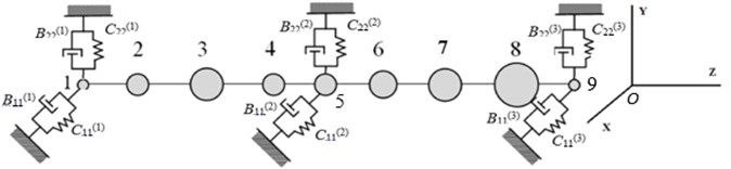
The mechanical model of HPR-MLPR system of TU consists of two weightless shafts having bending stiffness and bearing the concentrated masses ( 1, ..., 9). The double-span shaft system of HPR-MLPR is mounted on three bearings. Coordinate axes , coincide with the main axes of stiffness of the most loaded middle bearing ( – axis of minimum stiffness, – axis of maximum stiffness). The design scheme of the two-span shaft system of HPR-MLPR is shown in Fig. 1. In that figure , are the parameters of stiffness and damping of the bearings (1, 2, 3 – bearing number, from left to right; 11 – for the values of the parameters in the direction of the axis , 22 – in the direction of the axis ).
It is assumed, that the HPR shaft during operation acquires an unrecoverable deflection due to the temperature instability or non-compliance with the conditions of TU start-up [1]. Herewith the axis of its deflection and the axis of the resulting deflection of the entire shaft line are flat curves lying in the or planes.
Fig. 1Design scheme of two-span shaft line
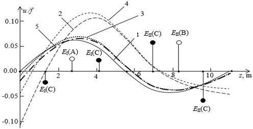
The initial form of the axis for removed from the left shafting support HPR-MLPR system is shown in Fig. 2 (curve ). The value can be called “curve shape parameter” of the initial deflection of HPR shaft.
Fig. 2Free shaft line axis with original bent HPR
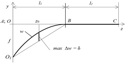
The shape of the actual deflection of the shaft line cannot be predicted in advance. It depends on many different factors. From many possible forms of the HPR shaft unrecoverable deflection for further calculations, as in [1], is adopted the following:
The values of the parameters in the calculation example correspond to the HPR-MLPR shaft system of turbine model K-300-23.5. They are: the length of each span of 5,5 m; the mass of the HPR 9600 kg, the mass of the MLPR 17800 kg; discrete masses 500 kg, 2800 kg, 3000 kg, 2800 kg, 1000 kg, 3000 kg, 5000 kg, 8800 kg, 500 kg; the bending stiffness of the HPR shaft 5,15∙108 N/m, of the MLPR shaft – 18,025∙108 N/m. Scheme of the compared bearings are shown in Fig. 3(a,b).
Fig. 3Basic schemes of support bearings: a) elliptical, 1 – lower insert, 2 – upper insert, 3 – tongue; b) six-block segmental, 4 – blocks, 5 – body
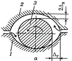
a)
b)
The values of the parameters (stiffness and damping coefficients) for the bearings of the compared types for the HPR-MLPR system are presented in Table 1.
Table 1The values of the parameters for the bearings
Type of bearing | Elliptical | Segmental | ||||
Bear., mass No. | (1), 1 | (2), 5 | (3), 9 | (1), 1 | (2), 5 | (3), 9 |
N/m | 0,022·109 | 0,157·109 | 0,114·109 | 0,127·109 | 0,172·109 | 0,164·109 |
N/m | 0,685·109 | 1,208·109 | 1,041·109 | 0,343·109 | 1,368·109 | 1,038·109 |
kg/s | 0,564·106 | 0,804·106 | 0,752·106 | 0,276·106 | 0,366·106 | 0,352·106 |
kg/s | 3,256·106 | 5,605·106 | 4,944·106 | 0,440·106 | 2,453·106 | 1.,17·106 |
3. Analysis of the forced oscillations amplitudes of HPR-MLPR system at coasting of TU
In Fig. 4 the curves of the acquired unrecoverable deflection of the two-span shafting, installed in the bearings of the types under consideration, and having the selected earlier deflection shape of the HPR, are shown. The value of the unavoidable deflection arrow was chosen to be equal to the limit value – 20 µm (ISO standart for thermal sample). The curves of the unrecoverable deflection of the shaft line correspond to: 1 – rigid supports; 2 – elliptical bearings, in the direction of the axis; 3 – elliptical bearings, axis; 4 – segmental bearings, axis; 5 – segmental bearings, axis. Labels (A) and (B) – correspond to the location of unbalances at the most vibro-active version of the symmetric unbalance; label C – to the location of unbalances at the most vibro-active version of skew-symmetric unbalance.
Fig. 4Curves of an avoidable deflection of HPR-MLPR system shaft line and options for the arrangement of unbalances
The natural frequencies and corresponding normalized oscillation forms for HPR-MLPR system with bearings parameters from Table 1 were calculated in [1].
Table 2Natural frequencies of HPR-MLPR system shaft line
Type of bearing | Elliptical | Segmental | ||
No of frequency | plane | plane | plane | plane |
1, rad/s | 100,8 | 182,7 | 110,9 | 178,7 |
2, rad/s | 112,4 | 213,1 | 136,1 | 213,3 |
3, rad/s | 242,8 | 538,7 | 295,0 | 510,1 |
For such a shaft line in the cases of both types of bearings has five natural frequencies less 314,16 rad /s, which corresponds to the operating speed of TU rotation. Herewith for every type of bearings three frequencies correspond to oscillations in the plane and although the two – to oscillations in the plane. The values of these frequencies are shown in Table 2 (bold). Among the natural frequencies of the shaft with a certain type of bearings there is the frequency, which corresponds to the form of oscillations with nodes close to the middles of each spans. For the shaft line in question, these are the following frequencies: for use of elliptical bearings – 242,8 rad/(s); for segmental bearings – 295,0 rad/s.
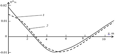
The normalized forms of oscillations corresponding to these frequencies are shown in Fig. 5. In the presence of skew-symmetric unbalances of both rotors forced oscillations in these forms can be excited during coasting of the TU and have oscillations amplitudes of bearings exceeding ISO standards. This can lead to the failure of the bearings and to emergency TU stop.
Fig. 5Eigen forms of shaft oscillations, what are dangerous for the bearings: 1 – φ3x *el for elliptical bearings; 2 – φ3x *seg for segmental bearings
The calculation of transient oscillations amplitudes of HPR–MLPR system shaft line in areas near the natural frequencies in skew-symmetric unbalance carried out according to the method proposed in [6]:
where is the amplitude of the -th concentrated mass at the point (Fig. 1), – the value of the -th form of oscillations at the point , – the natural frequency, – respectively, the reduced damping coefficient and the excitation parameter of oscillations in the form of the number . Here and further summation is not carried out for the indexes in parentheses.
The reduced damping coefficient [6] expresses by the relation:
where , , – the values of the main forms of rotor oscillations on located at points 1, 5, 9 supports (see Fig. 1) for each of the planes and : – damping coefficient for bearing number with oscillations in the plane, – with oscillations in the plane, ( 1, 2, 3).
The parameter in Eq. (2) reflects the impact of unbalances, acquired at the expense of unrecoverable deflection (Fig. 4), and residual mass unbalance with eccentricities (1,..., 9):
where – eigen forms of oscillations of the system with the corresponding type of bearings; – values of the unrecoverable deflection along the axes and (Fig. 4) at the masses attachment points on the shaft line (1,..., 9).
In paper [1] it is shown that the main contribution to the parameter value gives the parameter. It depends on the residual unbalance distribution along the length of the shaft line of the system and the type of the corresponding oscillations form. From Eq. (4) it follows, that the greatest value of is achieved if the components and have identical signs. Let in both cases of bearing type the residual unbalances vectors and the curves of the unrecoverable deflection lie in the same plane. At unrecoverable deflection of the HPR shaft, given by the Eq. (1), the maximum value of the parameter is achieved in the case of variant of skew-symmetric unbalance (see Fig. 4). In Fig. 4 the location of unbalances for the most vibro-active symmetric point imbalance at these frequencies (variant AB) is also shown [1]. Due to the lack of standards on the value of the maximum permissible moment of inertial forces, we proceed as follows. Let us assume that the unbalances (for the first span of the shaft line) and (for the second) with skew-symmetric unbalance of variant are equal to their maximum permissible values with symmetric point unbalance [1]. Then for unbalances (indexes 2, 4, 6, 8 correspond to the mass numbers on the shaft line) we obtain:
where – the module of the reduced residual unbalances [6], , – masses of HPR and MLPR, respectively.
The excitation parameter for the most vibroaction skew-symmetric unbalance of variant at frequencies given by Eq. (2), is described by the relation:
where – the main forms of vibration at frequencies and .
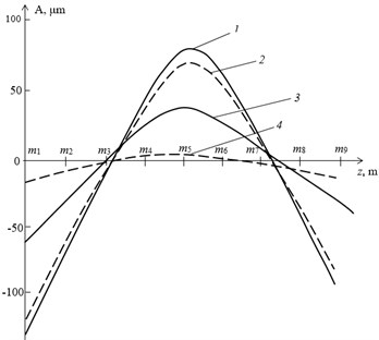
The values of the maximum displacements at the control points of the system shaft line with skew-symmetric unbalance of variant (see Fig. 4) are presented in Table 3. Unrecoverable deflection of the HPR corresponds to Eq. (1), parameters of using elliptical and segmental bearings are given in Table 1. For comparison, the values of maximum displacements at the same points are shown for the most vibro-active at the considered frequencies symmetric point unbalance of the (AB) variant [1]. The graphs of the maximum displacements at the control points of the shaft line from Table 3 are shown in the Fig. 6.
Table 3Maximum displacements of HPR-MLPR system
Maximum displacements in control points (µm) | |||||
Point, bearing No | 0; (1); | 0,5l; | l; (2); | 1,5l; | 2l; (3); |
Elliptical bearings: 242,8 rad/s | |||||
–8,3 | 0,7 | 4,0 | 0,7 | –3,7 | |
(C) | –51,8 | –4,8 | 33,0 | 6,6 | –32.4 |
(C) | –60,1 | –4,1 | 37,0 | 7,3 | –36,1 |
(АB) | –14,0 | 1,3 | 7,0 | 1,1 | –6,5 |
Segmental bearings: 295 rad/s | |||||
–9,6 | –0,9 | 6,1 | 1,2 | –6,0 | |
(C) | –121,6 | –11,3 | 77,4 | 15,4 | –76,1 |
(C) | –131,2 | –12,2 | 83,5 | 16,6 | –82,1 |
(АB) | –120,0 | –11,1 | 76,0 | 7,0 | 76,0 |
Analysis of the presented results in Table 3 and Fig. 6 results shows that in the case of skew-symmetric imbalance variant C the vibration amplitudes of the shaft line at the points of installation on the bearings exceed the amplitudes at symmetrical unbalance variant AB. For elliptical bearings the excess is 4,3 times, and for segment – 1,1 times. The amplitudes of HPR – MLPR system displacements with segmental bearings at the points of its installation on the bearings are more than 2 times higher than the amplitudes of the same system with elliptical bearings. In this case, the amplitudes at point A (see Fig. 2) for a system with segmental bearings are approximately 1,5 times higher than ISO standard (OA ≤ 90 µm) and are dangerous for the safety of bearings. For a system with elliptical bearings, these amplitudes are about 1,5 times lower than the upper limit of the ISO standard and are safe for bearings. For the HPR – MLPR system with the selected mechanical parameters, the use bearings of elliptical type reduce its vibroactivity by more than 2 times (see Table 3 and Fig. 6) compared to segmental.
Fig. 6The maximum displacements of HPR – MLPR system, mounted on bearings of two different types: 1, 2 – segmental bearings; 3, 4 – elliptical bearings; solid lines – skew-symmetric unbalance type C; dotted-symmetric unbalance type AB
4. Conclusions
On the basis of the proposed model of HPR-MLPR system shaft line (of turbine K-300-23.5 type) the amplitudes of the transient oscillations are estimated in the control points at coasting TU. The case with the most dangerous type of skew-symmetric unbalance (variant C) from the point of view of vibration activity of the TU shaft line is considered. This unbalance may be due to a residual unbalance of the shaft components and/or induced by a permanent deflection caused by the temperature instability of the rotors and/or non-compliance with the conditions of TU starting.
The influence of the most common types of bearings (elliptical and segmental) on the vibration activity of a two-span rotor with a skew-symmetric residual imbalance is considered and analyzed. The amplitudes in the control points of the system at frequencies lower than the frequency corresponding to the operating speed of TU are compared.
On base the proposed mechanical model of the HPR-MLPR system shaft line with the selected design parameters, it is shown that the use of elliptical bearings is safer, in terms of ISO standards, and therefore the most appropriate.
References
-
Volokhovskaya O. A., Barmina O. V. The effect of residual imbalance type in vibration activity of double-span rotor with different curvature of the axis under rundown. Journal of Machinery Manufacture and Reliability, Vol. 47, Issue 5, 2018, p. 403-411.
-
Edwardsa S., Leesm W., Friswel I. Experimental identification of excitation and support parameters of a flexible rotor-bearings-foundation system from a single run down. Journal of Sound and Vibration, Vol. 232, Issue 5, 2000, p. 963-992.
-
Sinha J. K., Friswell M. I., Lee A. W. The identification of the unbalance and the foundation model of a flexible rotating machine from a single run down. Mechanical Systems and Signal Processing, Vol. 16, Issues 2-3, 2002, p. 255-271.
-
Mogal S. P., Lalwani D. I. Experimental investigation of unbalance and misalignment in rotor bearing system using order analysis. Journal of Measurements in Engineering, Vol. 3, Issue 4, 2015, p. 114-122.
-
Schweizer B. Dynamics and stability of turbocharger rotors. Archive of Applied Mechanics, Vol. 80, Issue 9, 2010, p. 1017-1043.
-
Kostyuk A. G. Dynamics and Strength of Turbomachines. MPEI Publishing House, Moscow, 2000, p. 479.
About this article

