Abstract
Grinding is a finishing process used in almost every industry. The purpose of this research is to study the effects of grinding on aluminum. Finite Element Method (FEM) is used to numerically simulate grinding by using microscale modeling. It is found that though under grinding, stress mises developed do not exceed yield stress. The force variation and displacement parameters have been correspondingly discussed. The effects of grinding on the workpiece with and without lubrication.
1. Introduction
Surface finishing process like grinding is complex because of multiple cutting edges. The quality of workpiece often depends on workers skill and experience. Slightest error would make workpiece incompatible to use. Especially in fields like aerospace and bio medical engineering where precision is of utmost importance. Many researches [1] were dedicated to find optimal conditions of performing grinding operation for better surface finish.
Experimental analysing of this process under confined conditions is good for validation of grinding process. Performing experimental analysis under different conditions would involve a lot of time and money. Finite element analysis would be a fine approach to this problem. Results obtained through numerical simulation would be same as what we obtained in experimental procedure. This could save both time and money.
The quality of a simulation depends upon the model we have chosen. Models are of two types physical model and empirical model. Physical or mathematical models are based on the applications of physical laws like grinding force models, chip thickness models, grinding models etc. On the other hand, empirical models are based on the measured values. Physical models have broader application compared to empirical models but they are not always feasible in real life scenarios. Both physical and empirical models are used in this simulation. Generally grinding is modelled as a mechanical process in which we analyse the interaction between grinding wheel and workpiece, this is called macro scale modelling. There is one more approach in which single grit machining is modelled, this is known as micro scale modelling [2-5].
In this paper we intend to demonstrate the grinding process using both physical and empirical model with the help of finite element modelling. By using finite element modelling we simulate interaction of grinding grit and workpiece in Abaqus/Standard. Materials we use are grinding grit made of steel and aluminium workpiece [6].
2. Simulation
Abaqus consists of different components to completely define, analyse and obtain results of a problem.
2.1. Discretized geometry
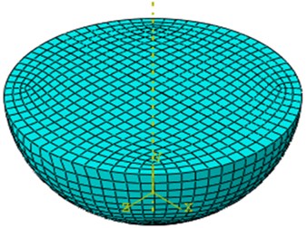
Both workpiece and grit are designed on Abaqus itself. Workpiece is designed by extruding a rectangle while grit is designed by rotating a quadrant of circle. Dimension of workpiece is 1×1×1 mm and radius of grit is 0.05 mm. Hexahedral elements are the recommended solid(continuum) elements. Three-dimensional hexahedral element. Strains are more accurate at integration points and integration point of the C3D8R element is located in the middle of an element. So, small size elements are needed to capture stress concentration at the boundaries.
Fig. 1Work piece geometry
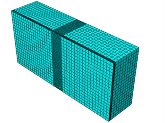
Fig. 2Grit geometry
2.2. Mesh
For this simulation, the Hex type mesh is used. The hex form meshed is chosen because it gives the best result and also at lower cost and processing time. In the contact area, there is a fine mesh along the cutting path to ensure the best result. Structured meshing is applied to specific model topologies using pre-established mesh patterns. Nevertheless, in order to use this method, complex structures typically need to be separated into simpler regions.
2.3. Material properties
Grit material (steel): density () = 7700 kg/m3, Poissons ratio () = 0.28, Youngs modulus () = 215 GPa.
Work piece material (aluminum): density () = 2,710 kg/m3, Poissons ratio () = 0.35, Youngs modulus () = 69 GPa.
Johnson cook is a empirical relation developed by Jonson and cook, It is used to model damage evolution and predict failure in a material.
Table 1Johnson cook damage of steel
Melting temperature | Transition temperature | ||||
324.1 | 113.8 | 0.42 | 0 | 660 °C | 0 |
2.4. Boundary conditions
General contact allows us to define contact between many or all regions of a model with a single interaction. Interactions typically include all bodies in the model. Very few restrictions on the types of surfaces involved for contact constrained we use penalty method. The friction coefficient take into account is 0.15. General contact allows you to define contact between many or all regions of a model with single interaction. The surfaces that can interact with one another comprise the contact domain and can span many disconnected regions of a model. Contact pairs describe contact between two surfaces. Requires more careful definition of contact. Every possible contact pair interaction must be defined.
2.5. Analysis type
Abaqus can carry out two types of simulations static and dynamic analyses. In this problem we use dynamic analysis.
3. Results
The stress produced during this simulation is studied below. The Contour below shows the distribution of Stress. The depth of cut is 0.05 mm and is kept constant for complete simulation. We can see that the stress of 1748 N/mm2 or 1748 MPa is developed by grinding.
The deformation in the workpiece is also studied and shown in Figures below.
Fig. 3Stress mises contour in MPa
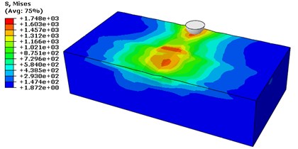
Fig. 4Deformation contours U1, U2 and U3 in mm
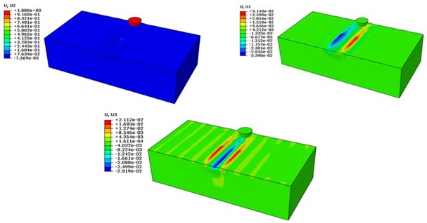
Fig. 5Figure showing reaction forced developed due to deflection and Shear stress caused due to frictional contact
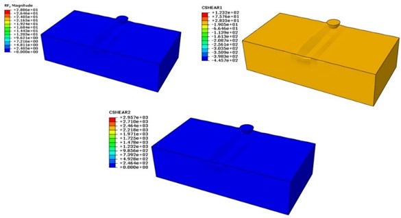
Fig. 6Figure showing load deflection curve
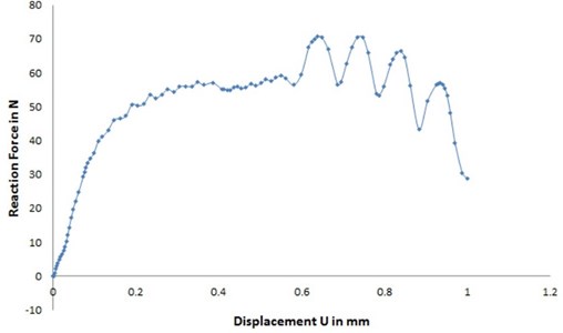
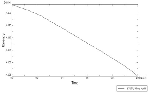
Fig. 7Figure showing total energy curve
4. Conclusions
This research manifests the importance of lubricant in grinding. Grinding of aluminum under dry conditions resulted in higher grinding forces and high specific energy requirement. Consequently, grinding damages are more if the aluminum is ground under dry condition.
We also get the stress developed in workpiece. The defects that can affect the fatigue life of the components in service as these may act as areas of stress concentration and favorable sites for earlier initiation of fatigue cracks.
References
-
Tönshoff H. K., Peters J., Inasaki I., Paul T. Modeling and simulation of grinding processes. Annals of the CIRP, Vol. 41, Issue 2, 1992, p. 677-688.
-
Park H. W., Liang S. Y. Micro grinding force predictive modelling based on microscale single grain interaction analysis. Manufacturing Technology and Management, Vol. 12, 2007, p. 25-28.
-
Klocke F. Modelling and simulation of grinding processes. 1st European Conference on Grinding, 2003.
-
Doman D. A., Bauer R., Warkentin A. Experimentally validated finite element model of the rubbing and ploughing phases in scratch tests. Proceedings of the Institution of Mechanical Engineers, Part B: Journal of Engineering Manufacture, Vol. 223, 2009, p. 1519-1527.
-
Takenaka N. A study on the grinding action by single grit. Annals of the CIRP, Vol. 13, 1966, p. 183-190.
-
Tahsin Opoz, Chen Xun Numerical simulation of single grit grinding. Proceeding of the 16th International Conference on Automation and Computing, Birmingham, UK, 2010.
About this article

