Abstract
A mathematical model of plane grinding by the tool which is modeled as a disc with distributed on its surface abrasive grains, owning random geometric characteristics in the paper is analyzed. Cutting is modeled separately by each grain under kinematically given tool motion. The system of equations, describing the relations between the surface coordinate cut by permanent grain and the surface coordinate machined by previous grain, is obtained. The solution for a single track is analyzed, determining the configuration of workpiece surface under multiple grains’ passages. An array of varying dimension is used, in order to store the change of all grains’ cutting thickness in grinding process. The interaction forces at each grain being in contact with the machined surface are summarized at each time step. The dynamic model is based on the consideration of insufficient rigidity of the technological system characteristics, which is inherent while grinding of complex parts in aircraft and space industry. The arising vibrations can significantly affect on precision and surface quality. The problem is especially important in processing complex parts, such as turbine blades, where the precision and surface roughness, residual stresses define the process efficiency. The estimation of system parameters and cutting conditions influence on the machined surface errors generated while processing simulation is analyzed. It was shown that system vibration is excited with the frequencies of grain pass (rotation frequency) and with the eigenfrequencies of the elastic dynamical system also, which are typical for the regenerative mechanism of excitation.
Highlights
- A stochastic model of plane grinding dynamic is elaborated
- Cutting while grinding process is realized by a tool with a large amount of abrasive grains with random characteristics, distributed on the outer cylindrical surface of the grinding wheel
- The tool and workpiece dynamics is analyzed considering vibrations excitation due to regenerative mechanism
- Texture of surface as a result of modeling considering system dynamic is constructed
- The main influence on system stability has the rigidity of tool or workpiece
- The geometry of grain may affect on surface roughness and processing time for the required quality obtaining
1. Introduction
The process of profile deep grinding by special highly porous abrasive tool is one of most effective method of complex profile surface final processing of hard-to machine heat-resistant steel and strain-hardened alloys. This method provides stock removal up to 10-15 mm and the required accuracy and high quality of workpiece surface layer. Contour deep grinding is widely used for base surface final processing of turbine blades, tooth-wheel contour, thread profile and groove slots for several branches of industry. However, the accuracy requirements for shaped surface and its quality, and parts operational characteristics have been significantly improved.
Many researches carried out investigations devoted for grinding process modeling. Their approaches were mainly focused on simulation of grinding wheel-workpiece interaction during cutting. A comprehensive review of present state in grinding modeling has been given in [1-3]. Most of the models are only valid for a specific combination of the technological system. Elaboration of adequate models in details describing the grinding process behavior can sufficiently improve quality and surface accuracy. Cutting while grinding process is realized by a tool with a large amount of abrasive grains, distributed on the outer cylindrical surface of the grinding wheel. Grains are playing the role of cutters which remove the machined material. Each grain cuts surface formed by the preceding grit being situated at this surface point. This process is accompanied by high stress and temperature in the zone of contact of grain and material [1]. The periodical grain entrance in the machined material is a source of forced vibrations and regenerative mechanism leads to a self-vibration excitation [4]. In frame of standard practice grinding is regarded as a process of edge cutting machining like milling, and each abrasive grain works as a separate cutter. The instant cutting layer depth being in contact with workpiece surface at that moment is supposed equal for every grain. The resultant cutting force can be determined by empiric relation [1] as function of cutting conditions and system parameters. The relation contains some empiric coefficients which are experimentally obtained and require the significant efforts for the specified conditions. Another approach assumes that each cutting grain being in contact with workpiece surface cuts its own layer and cutting force at the separate grain is proportional to its uncut chip. The resultant cutting force is determined as the vector sum of forces acting at every grain being in contact with workpiece surface [5-7]. The number of active cutting grains is calculated on the base of assumption of uniform grain distribution on tool surface. The instant depth of cut layer for each grain can be calculated by analytical relations [8] or special geometric algorithms [9]. At the moment cut depth depends on the instant relative position of grinding tool and workpiece and it vary due to tool motion and possible workpiece vibrations. In general, the geometry characteristics of grains and their distribution on tool surface have random character [10].
The well-known methods published in papers and monography [1] for setting the grinding tool characteristics and cutting conditions make possible attain the specified quality parameters of surface layer under deep grinding. But change the complex contour surface machining onto the NC multi-coordinate grinding machine the full-rate realization of deep grinding process possibilities looks troublesome. The influence of process dynamics and thermo-mechanical behavior in cutting region on output characteristics of machined workpiece’s each elementary surface should be considered while the cutting process design. It makes possible to reveal the most critical surface under quality criteria which defines scientifically grounded cutting conditions for full surface processing. A system of shape formation process estimation of complex contour is required which is based on the dynamic and thermo-mechanical processes interaction, which defines the output parameters of dimensional accuracy and machined surface quality. The problem solution by experimental research on test parts is performed, but it requires significant expenses and time. The elaboration of the process simulation models and algorithms of their analysis provides more efficient approach of efficiency estimation.
2. Model description
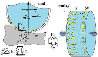
Grinding tool represents a disc of diameter and width . Abrasive grains are uniformly distributed on its surface and have crystal-like shape of random geometry. While processing each grain cuts own chip and thus at the same time form the surface of workpiece after pass of the following grains. In most publications while grinding tool and machined surface interaction the macroscopic approach is applied [2-4]. The tool surface is modeled as cylinder moving along the workpiece surface and cutting off the material that appears under given depth of penetration. This method does not allow simulating the microscopic effects generated by grains interaction with workpiece surface. The microscopic approach makes it possible analyzing the texture formation while grinding considering the dynamic system behavior accompanying the process. Domala, Salisbury [11, 12], Inasaki [13], Chen [14] applying the microscopic approach have analyzed the process kinematics. Inasaki [13] employed 3-D wheel surface profiles for grinding tool perimeter storing the digitized coordinates in computer for later use in simulation. The scanned surfaces information is analyzed and processed for determination integral characteristics in order to derive generalized information of grinding wheels geometry. Applying these statistical grinding wheel topography data, such as mean values and random characteristics of grain size, grain distribution in multiple directions modeling the digital grinding wheel surface topographies is possible. The grain geometry for the simplicity usually has been approximated by simple spheres [2, 14, 15] or cones [16] or has been modeled as basic regular solid (octahedrons, cuboids, and tetrahedrons) [17]. The disposition of grains on wheel surface while modeling is defined applying random distribution laws [14]. The three-dimensional topography of the grinding wheel by a large number of spheres randomly spread on its surface is generated in this paper. The process of grinding is investigated by simulating the cutting action of every grain considering its kinematics. The elastic deformation of the cutting grains and the plastic penetration caused by the cutting grains on the workpiece are considered.
The stochastic model of grinding tool in this paper is analyzed applying the following assumptions: 1) abrasive grains are uniformly distributed on the grinding wheel surface in such a way that neighboring grains disposed in the same plane perpendicular to the tool axe are regularly spaced (on the few specified circumferences (Fig. 1). Central angle between these grains is constant; 2) Grains have random geometry (height , conical angle , inclination angle of grain axe relative to radial direction ) as it is shown in Fig. 1.
In axial direction grains are disposed by some circumferential trail, which are displaced in circumferential direction by random angle. Under tool rotation each trail cuts own surface independently of each other. Total trails number 50 in the paper was specified. Generally, the geometric parameters of grinding tool are specified by nominal values of parameters with random distribution by normal probability law [16].
Fig. 1Schematic model of grinding process with stochastic grains geometry
In the paper grain height as random value with normal probability law distribution is specified. The distribution function is determined by Riemann integral [18]
Conical angle of grain actually represents the rake angle of cutting wedge with opposite sign. This angle is assumed as strongly asymmetric distributed random value around –30°, which is well described by Relay distribution function [18].
Grain’s yaw angle is assumed as random value distributed by normal law with mean value 0 and standard deviation, 6. We assume that random geometric parameters are independent values. Thus, the correlation moments 0, 0, 0.
Even grains are uniformly distributed on each trail small angular displacement between grains is introduced. The angular displacement is assumed as random value with uniform distribution (equi-partition) law [18].
Table 1Parameters of grain distribution
Parameter | Distribution law | Min | Max | Mean value | Standard deviation σ |
[µm] | Normal | 50 | 110 | 80 | 10 |
[°] | Relay | 5 | 70 | 37.59 | 19.65 |
[°] | Normal | –30 | 30 | 0 | 10 |
[°] | Uniform | –0.036 | 0.036 | 0 | 0.021 |
3. Geometric relations for cut layer thickness calculation
While modeling of flexible workpiece grinding for process dynamics analysis the cut layer thickness of each grain being in contact with workpiece material is required. Plane surface of workpiece is discretized. The schematic of cut layer formation by following ()- and ()-grains moving on -th trail in details is described in [19, 20].
Surface geometry is described by discrete model for each -th trail. Disposition of surface is defined by coordinate measured in radial direction from grind wheel center intersecting -th grit to the workpiece surface. Model contains information about surface discretely with time step . The equations of new surface formation can be written as follows [19, 20]:
where – period of grain passage, – distance from workpiece surface at time for -th grain due to wheel rotation only; – surface coordinate saved in data base in MATLAB software; , – dynamic displacement projections on axis , ; – distance from -th cutting edge to uncut surface consisting of static part , dynamic part , and the amount of difference between the height of neighboring grits , – height of -th grain, – height of ()-th grain; – cut chip thickness for -th grain at time , – function that is equal maximal of values 0 or , (it means that uncut chip thickness must be not negative); – coordinate of intersection point of -th grain axe at time with workpiece surface at time expressed in polar coordinates; – function which interpolates its value by points given in data base; – function which defines is it -th grain in contact region or not; – angle of grain exit from cut material.
The model describing the surface geometry of the -th track is discrete. Intersection of repetitive cutting occurs with several passes of the grinding wheel. Thus, the treated surface obtained at the previous pass of the circle becomes the untreated surface at the present pass of the circle (where, is the time between successive passes of the wheel). In this paper, we assume that 0.01 s.
The following assumptions are introduced: at 0 the coordinates of the grinding wheel centre in the coordinate system are [mm]. In the case of high stiffness of tool-part elastic system, displacements due to vibration can be neglected. The solution of the system of equations is obtained under the conditions , .
In this paper we assume that the workpiece is fixed elastically and can vibrate in plane, while the grinding wheel rotates in rigidly fixed supports. For dynamic analysis it is more convenient to transform the tangent and normal component cutting forces , acting on separate grain into the coordinate system , as the forces , , using the relation Eq. (1) as follows:
4. Dynamic modeling considering displacements due to vibrations
Summing the cutting forces acting on all the grains, located in the contact zone of wheel and workpiece, the resulting forces acting on the grinding wheel Eq. (2) are determined:
The system of differential equations describing the grinding wheel’s motion has the form of Eq. (3):
where, – mass of grinding wheel; , – damping coefficients of tool support in direction of axis , ; , – reduced stiffness of tool support in direction of axis , .
In these calculations, we specify that: 2 kg, 632.4 [kg/s], 309.8 [kg/s], 20 [kN/mm], 30 [kN/mm]. Kinematic parameters of tool are given in Table 2.
To simulate the grinding process with consideration of detail’s compliance, the grinding process of parts with low stiffness is modelled as a plane system with two orthogonal degrees of freedom (Fig. 1). The equations of motion will have the same representation as Eq. (3). But variables and parameters in the equation will be concerned to workpiece ( – workpiece mass, , – coefficient of damping factors for workpiece fixation, , – coefficient of stiffness for part in the direction of and axes, reduced to the contact point).
Table 2Specified data for the simplified model of plane grinding
Angular speed of tool rotation, | 150 rad/s |
Feed speed, | 250 mm/s |
The radius of the grinding wheel | 105 mm |
Depth of cut | 0.2 mm |
Width of grinding wheel | 5 mm |
Number of tracks | 50 |
The number of grains at unit trail | 5000 |
Number of grains in the contact zone on unit trail | 49 |
The following dimensionless variables and notations are introduced:
The equations of workpiece motion Eq. (4) in dimensionless form are as follows:
where, , the workpiece natural frequencies: , – damping coefficients, are assumed as: 0.05, 0.02. Differential Eq. (4) are numerically integrated under the initial conditions: at 0, 0, , 0, .
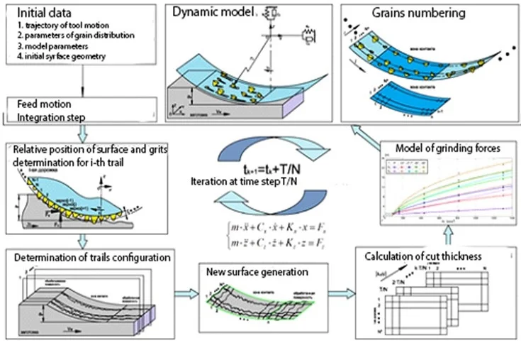
5. Full model structure
Structure of the elaborated full mathematical model of plane grinding dynamics in Fig. 2 is presented. The base block performs determination of the relative position of workpiece surface and grains, considering tool vibration and the specified feed motion. The wheel or workpiece motion is described by the differential equations of the second order Eq. (4).
For data base of surface coordinates the two-dimension array is applied, is trail number on the circle where . We assume that at time 0 first grain appears in contact region and its number is 1. The following grits are numbered counter-clockwise.
Fig. 2Block diagram of mathematical model of grinding process simulation
6. The simulation results of machined surface texture for test example
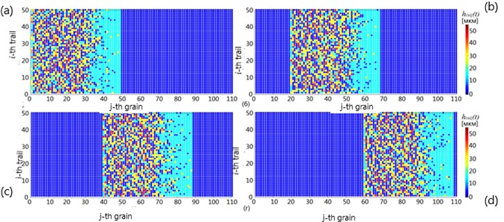
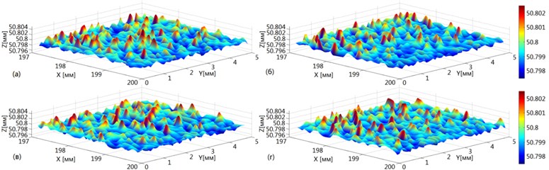
As the result of process simulation, the texture of machined surface is determined. The example of surface texture construction obtained by integration of model equations considering that tool and workpiece fixation is absolutely rigid (, ) on Fig. 3 is shown. The variation cut chip thickness for -th grain -th trail in time for 4 sequential time moments in Fig. 4 is shown.
Fig. 33-D texture of machined surface obtained by integration at time t= 100·T/N
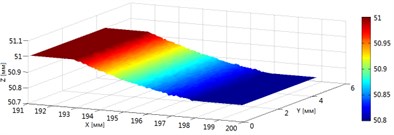
Fig. 4Variation of cut chip thickness for j-th grain i-th trail at time: a) t=T/N; b) t= 20T/N; c) t= 40T/N; d) t= 60T/N
The enlarged texture of machined surface determined by model simulation without (Fig. 5(a)) and with vibration consideration (Fig. 5(b)) at time for different variants of grains disposition with randomly specified parameters are presented.
7. Conclusions
If compare images in Fig. 5(a) and Fig. 5(b) we can conclude that under all other conditions being equal mean value of machined surface coordinate with vibration consideration higher than with no vibrations. It can be explained by elastic deflection of tool or workpiece in case of flexible fixation. But we can see that for case of modeling with vibration consideration the texture has more picks per unit surface.
Fig. 5Texture of machined surface obtained by modeling at time t=100T/N
a)
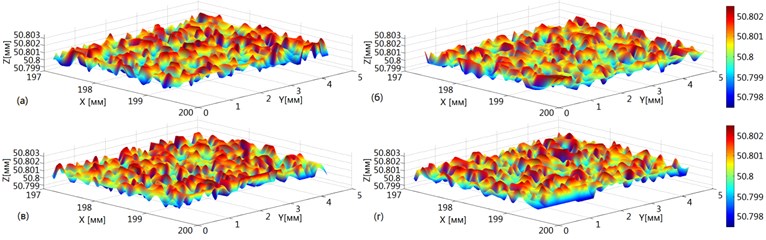
b)
The integral characteristics of surface quality by Monte Carlo method are calculated, applying stochastic processing of modal output data. The following parameters for estimation of surface quality were analyzed: Mean – mean value of surface coordinate (), which defines the mean line of surface profile, – arithmetical mean value of profile deflection, which is determined as arithmetical mean profile deflection absolute value – within the limits of basic section , – mean step of profile irregularity. The coordinates of machined surface are determined by the Eq. (4) for each tool trail after tool passage. In Fig. 5 enlarged image is shown of machined surface profile obtained by simulation at time instant without taking into account vibrations and considering workpiece vibrations. If compare the parameters of surface waviness obtained without vibration consideration and with vibrations we can see that average value Mean is increased slightly ( = 50,7989 mm, = 50,8006 mm). It can be explained by the presence of elastic deflection of workpiece. At the same time decreases (= 0,6437 μm, = 0,5264 μm), that confirms the influence of fastening stiffness on machined surface waviness. decreases also ( = 0,4115 mm, = 0,3421 mm), but on the surface calculated considering workpiece vibrations quantity of peaks within unit interval grows. Random parameters of tool grits in the paper are considered. Their influence on process stability is inappreciable. The main influence on system stability has the rigidity of tool or workpiece. The geometry of grain may affect on surface roughness and processing time for the require quality obtaining. The calculated cutting forces considering system vibration can be applied for tool parameters and cutting conditions determination providing the specified efficiency of processing.
References
-
Marinescu I. D., Hitchiner M., Eckart U. Handbook of Machining with Grinding Wheels. CRC Press, 2007.
-
Brinksmeier E., Aurich J. C., Govekar E., Heinzel C., Hoffmeister H. W., Peters J., Rentsch R., Stephenson D. J., Uhlmann E., Weinert K., Wittmann M. Advances in modeling and simulation of grinding processes. CIRP Annals, Vol. 55, Issue 2, 2006, p. 667-696.
-
Brecher C., Esser M., Witt S. Interaction of manufacturing process and machine tool. CIRP Annals – Manufacturing Technology, Vol. 58, 2009, p. 588-607.
-
Altintas Y. Manufacturing Automation: Metal Cutting Mechanics, Machine Tool Vibrations, and CNC Design. Cambridge University Press, 2000.
-
Aurich J. C., Biermann D., Blum H. Modelling and simulation of process: machine interaction in grinding. Production Engineering, Vol. 3, 2009, p. 111-120.
-
Werner K., Klocke F., Brinksmeier E. Modelling and simulation of grinding processes. Proceedings of the 1th European Conference on Grinding, 2003.
-
Voronov S. A., Kiselev I. A., Ma W., Shirshov A. A. Simulation dynamical model of grinding complex parts. elaboration of simulation methods. Science and Education, BMSTU, EI N FS 77-48211, Vol. 5, 2015, p. 40-57, (in Russian).
-
Voronov S. A., Ma W. Mathematical modeling of the cylindrical grinding process. Journal of Machinery Manufacture and Reliability, Vol. 46, Issue 4, 2017, p. 394-403.
-
Kiselev I. A., Voronova I. S., Shirshov A. A., Nickolaev S. M. Simulation dynamical model of grinding complex parts. model of tool and workpiece. Science and Education, BMSTU. EI N FS 77-48211, Vol. 9, 2015, p. 1-16, (in Russian).
-
Zhen Bing Hou, Komanduri R. On the mechanics of the grinding process – Part I. Stochastic nature of the grinding process. International Journal of Machine Tools and Manufacture, Vol. 43, 2003, p. 1579-1593.
-
Domala K.-V., Salisbury E.-J., Moon K.-S., Sutherland J.-W. A three-dimensional geometric model for the surface texture generated by a single pass of the wheel in a surface grinding process. ASME Manufacturing Science and Engineering, MED-2-1/MH-3-1, p. 363-375, 1995.
-
Salisbury E. J., Domala K. V., Moon K. S., Miller M. H., Sutherland J. W. A three-dimensional model for the surface texture in surface grinding, part 1: surface generation model. Journal of Manufacturing Science and Engineering, Vol. 123, 2001, p. 576-581.
-
Inasaki I. Grinding process simulation based on the wheel topography measurement. Annals of the CIRP, Vol. 45, Issue 1, 1996, p. 347-350.
-
Chen X., Rowe W.-B. Analysis and simulation of the grinding process part I-part III: generation of the grinding wheel surface. International. Journal of Machine Tools and Manufacture, Vol. 36, 1996, p. 871-906.
-
Gong Y.-D., Wang B., Wang W.-S. The simulation of grinding wheels and ground surface roughness based on virtual reality technology. Journal of Materials Processing Technology, Vol. 129, Issues 1-3, 2002, p. 123-126.
-
Cooper W.-L., Lavine A.-S. Grinding process size effect and kinematics numerical analysis. Journal of Manufacturing Science and Engineering, Vol. 122, 2000, p. 59-69.
-
Warnecke G., Zitt U. Kinematic simulation for analyzing and predicting high-performance grinding processes. Annals of the CIRP, Vol. 47, Issue 1, 1998, p. 265-270.
-
Hecker R., Liang S. Y. Predictive modeling of surface roughness in grinding. International Journal of Machine Tools and Manufacture, Vol. 43, 2003, p. 755-761.
-
Voronov S. A., Ma W., Voronova I. S. Stochastic model of abrasive process. Kynematic of plane grinding. Izvestiya Vyshich Uchebnych Zavedeniy, Mashinostroenie, Vol. 11, 2017, p. 68-78, (in Russian).
-
Voronov S. A., Ma W. Stochastic model of abrasive process. Dynamics of plane grinding. Izvestiya Vyshich Uchebnych Zavedeniy, Mashinostroenie, Vol. 1, 2018, p. 26-36, (in Russian).
About this article

