Abstract
The article focuses on the analysis of thermomechanical modeling of cutting by single abrasive micro-size grain while the process of grinding. In this research, applying the Johnson-Cook” material model, which relates the intensity of stress with strain rate, temperature and the accumulated plastic strain. Using arbitrary Lagrangian-Eulerian (ALE) approach makes it possible avoid the distortion of finite elements in the simulation of chip-formation under large deformations. The simulation allows predicting cutting force for processing workpiece of titanium alloy Ti6Al4V by single grain grinding.
1. Introduction
Grinding is a finishing machining operation, which is used to obtain the desired surface roughness and specified precision of shape characteristics. In the process, a large amount of abrasive grains, distributed on the outer cylindrical surface of the grinding wheel, play the role of cutting tools and remove unwanted material. Thermomechanical behavior of the material of workpiece is determined by its interaction with the cutting tool during the formation of chips. The cutting process takes place at high pressure and temperature in the zone of contact of grain and material [1]. The periodical grain entrance in machined material leads to the dynamical workpiece and tool behavior that can decrease the surface quality and the accuracy of processing. The arising vibration have the mechanism of forced vibrations and the regenerative mechanism due to cutting by each grain the surface that was generated by the previous grain [2]. The determination of cutting forces under the specified cutting conditions is required for the vibration analysis. It can be done by modeling of single grain and machined material interaction while cutting.
Therefore, the mechanism of micro material removal with a single grain and the process of chip formation are necessary to investigate in details, as they are determined by the properties of workpiece material, cutting thickness, cutting speed, geometry of cutting edge, and etc. Simulation of cutting process with single grain is conducted by using “Abaqus/Explicit”, which allows to predict the shape of the chips, cutting forces, the surface quality, to estimate the residual stresses in workpiece, and determine the effect of operating parameters on the quality of the treated surface, in order to optimize primary operational parameters and geometry of cutting tools [3].
2. Description of cutting model with a single grain
Real abrasive grain usually has shape of pyramid with flat faces. Grain enters into the material like a cutting wedge with a negative rake angle. In this case, the chip material easily slides along the rake face of the grain, after been separated from the workpiece material. In order to avoid infinity in the calculation of FEM model, the side four sharp edges of pyramid are chamfered while the geometry modeling of pyramidal shape grain. Taking into account of grain deterioration in grinding process, the bottom of grain is covered by spherical top with a given radius 10 μm. Geometric scheme of pyramid-shaped grain is shown in Fig. 1.
In fact, each abrasive grain on grinding wheel, entering into the material, moves along a path close to a circle. For simplicity, the trajectory is replaced by the path shown in Fig. 2, consisting of three straight segments. This designed scheme of grain cutting can reduce time of computation and allows explore the cutting forces acting on single grain. We assume that, the process of exit from cutting of grain from the material in the third stage doesn't greatly change characteristics of the cutting forces, so the results of the third stage are not essential in simulation. Thus modeling is limited to two stages, which can significantly reduce the time of calculation. Besides, all the dimensions are in micrometers.
Fig. 1Geometric scheme of pyramidal shaped grain
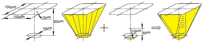
Fig. 2Simulation path of process single grain cutting
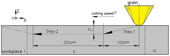
We assume that, the movement of grain is specified kinematically and doesn’t be influenced by the interaction between tool and workpiece material. Grain penetrates into the workpiece material with a constant cutting speed (specified 5 m/s). At step-1, grain enters into the material with the depth, which varies linearly from 0 to , and passes along horizontal direction through 100 μm. Next, at step-2, the grain moves with constant speed and the depth of , and passes on at 200 μm. Modeling was performed for a given cutting thickness 40 μm.
Zone of deformed surface, where grain penetrates into the material, is several degrees less than the dimensions of the part. Therefore, the actual shape and dimensions of the whole part it is of no importance, and the workpiece is considered as a cuboid. Due to the large temperature gradient and plastic deformations in the contact area, it requires a fine mesh of finite elements. Using uniform grid for workpiece is not efficient, besides it significantly increases the amount of computation.
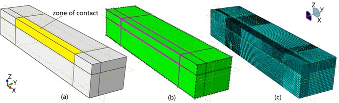
In the simulation approach ALE is used for finite element mesh construction with the help of built-in procedures of software “ABAQUS”, in order to get a normal chip formation without distortion of finite elements. Fig. 3 shows construction of grid.
Fig. 3Construction of grid: a) partition of blocks, b) initial mesh, c) the grinding part
3. Approach ALE for the formation of chips
The three main approaches are widely used in the field of metal cutting FEM simulation: Lagrangian, Eulerian, and Arbitrary Lagrangian-Eulerian (ALE).
Approach ALE combines peculiarity of both approaches Lagrangian and Eulerian. The ALE approach FE mesh is neither spatially fixed nor attached to the material. The mesh moves with the flow of material, determination of displacement is performed applying the Lagrangian approach, meanwhile, at each iteration, the grid is rebuilt, determination of velocities is performed applying Euler approach.
The idea of modeling used in metal cutting consists in following way. In the zone near the edge of the cutting tool, Lagrange approach is used, while to analyze the areas where there is a free-boundary flow of chip material, Euler approach is used. This eliminates significant distortion of the grid elements [4].
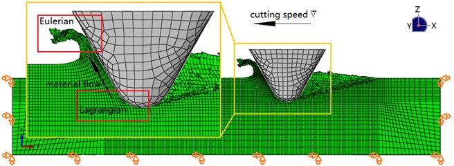
Fig. 4 shows a scheme of ALE approach and the boundary conditions for workpiece in the simulation. Workpiece is modeled by using element of type C3D8RT, which is an 8-node thermally coupled brick, considering 3-D displacement and temperature, reduces integration time, and controls element parasitic form generation. The number of elements is 210540. The grain is considered as a rigid body.
Fig. 4Scheme of ALE approach and boundary conditions of workpiece
4. Material model and properties
The behavior of the workpiece material during deformation beyond the elasticity limit is considered by using thermo-elastic-plastic “Johnson-Cook” constitutive model. This model relates the intensity of the stress with strain rate, temperature and the accumulated plastic strain [5]:
where, – equivalent stress, – equivalent plastic deformation, – actual strain rate, – basic effective strain rate, 1.0 s-1, – room temperature, – melting temperature of the material. – characteristic coefficient, having dimension of stress, (yield strength of material), – characteristic coefficient, having the dimension of stress, – the exponent of hardening effect of plastic deformation, – coefficient of influence of the strain rate (dimensionless), – material constant considering heat softening (dimensionless).
Coefficients of model “Johnson-Cook” for material Ti6Al4V are shown in Table 1 [6].
Table 1Coefficients of model “Johnson-Cook” for material Ti6Al4V
(МPа) | (МPа) | |||
1098 | 1092 | 0.93 | 0.014 | 1.1 |
In the simulation the deformation of the material is supposed to use model of cumulative damage summation :
where, – increment of effective plastic strain in FE on th step of integration time.
The value of critical accumulated strain is used as the criteria of material damage, which is determined by the “Johnson-Cook” destruction model:
where, – the hydrostatic pressure, – the equivalent von Mises stress, to – material damage parameters, that show the influence of strain, strain rate and temperature on the material damage.
To describe fracture of material the “Johnson-Cook” model in the package “Abaqus” is applied which states that, when the damage parameter of FE reaches 1, then destruction of the FE occurs. The parameters of the damage law in “Johnson-Cook” material model for Ti6Al4V are given in Table 2 [7].
Mechanical, physical and thermal parameters of the workpiece material are given in Table 3 [8].
Table 2parameters of the damage law in “Johnson-Cook” material model for Ti6Al4V
–0.09 | 0.27 | 0.48 | 0.014 | 3.87 |
Table 3Mechanical, physical and thermal parameters of the workpiece material Ti6Al4V
Mass density (kg/m3) | 4430 | Specific heat (J/kg°C) | 526.3 |
Young’s modulus (MPa) | 118 | Thermal conductivity (W/m°C) | 6.7 |
Poisson’s ratio | 0.349 | Thermal expansion coefficient (µm/m°C) | 9.2 |
(°C) | 1640 | (°C) | 20 |
5. Finite element simulation results
Heavily distorted elements during simulation of metal cutting can be removed from the mesh by setting the damage variables (SDEG), so as to reduce the possibility of termination program. Element deletion occurs when the degradation value (SDEG) calculated at a specified increment time reaches 1, ultimately element failure occurs via element deletion technique. Fig. 5 shows distribution of the damage variable (SDEG) in the simulation.
The process of chip formation during the immersion of grain into material is shown in Fig. 6. Several pieces of material are distributed out of workpiece into air. This phenomenon is related to the fact that; material is separated from workpiece in the region around the edge of pyramidal shaped grain. Chips are formed during the extrusion of the material under the grain, and slide along the rake face of grain.
The von Mises stress distribution through the simulation path is illustrated with contour lines in Fig. 6. It is very obvious to detect stress change during process. The maximum stress is achieved at the area near the end of step 1, and near the beginning of step 2, also at the region where the grain changes the direction of its motion. It’s interesting that, the stress decreases, along the path of grain immersion into the material. But if determine the temperature distribution, which is shown in Fig. 7, we can see that maximum temperature is reached at the contact area of grain and material. This coincides with the fact that, metal cutting is the thermomechanical process with high temperature and high stress. Besides, cutting heat will soften metal, consequently influences on stress distribution in workpiece.
Fig. 5Scalar element degradation parameter D (SDEG) during simulation of chip-formation
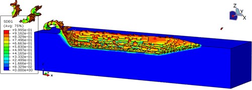
Fig. 6The von Mises stress distribution during simulation of chip-formation (Semi-sectional view)
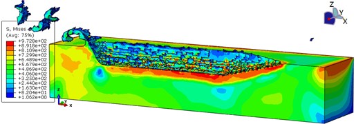
Fig. 7Temperature distribution during simulation of chip-formation (Semi-sectional view)
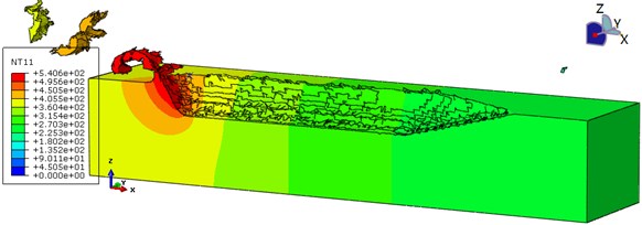
Fig. 8Configuration of cross-section (Ac – cross-sectional area of the contact grain and material)
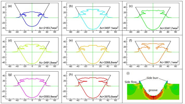
Fig. 8 shows the configuration of grain and material cross-section. Obviously, the immersion of grain into material, formed groove, side flow, side burrs, as shown in Fig. 9(i).
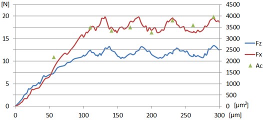
Finally, the cutting forces of chip-formation with a single grain are shown in Fig. 9. At step-1, cutting forces increase, when the grain moves forward, meanwhile, the cutting thickness also increases linearly with the position of the grain. In most cases of approximate calculation, the cutting force can be seen as proportional to the cutting thickness.
At Step-2, cutting forces have some obvious waves with 4 peaks and 3 troughs, which are consistent with the appearance of chip separation into pieces in the simulation, as shown in Fig. 7. Comparing to the change of cross-sectional area of the contact grain and material (), as shown in Fig. 10, we can assume that, there is some correlation between cutting forces and . In this paper only the results of the simulated case for cutting thickness 40 μm are presented. The results are not enough to find the correlation between cutting conditions and forces. It’s necessary to add several simulations with different cutting thickness in future and investigate in details. It will allow construct mechanistic model which can be used for vibration analysis under grinding.
Fig. 9The dependence of cutting forces (Fz, Fx) and cross-sectional area of the contact grain and material (Ac) on the position of the grain
6. Conclusions
FEM model of metal cutting is analyzed; it confirms that approach ALE is very convenient to investigate chip-formation. The results of FEM simulation provide stress and temperature distribution, chip formation during the implantation of single grain. Configuration of cross-section is observed, cross-sectional area of the contact grain and material is measured, and dependence of cutting forces on grain path is also given.
References
-
Astakhov V. P., Shvets S. The assessment of plastic deformation in metal cutting. Journal of Materials Processing Technology, Vol. 146, 2004, p. 193-202.
-
Altintas Y., Weck M. Chatter stability in metal cutting and grinding. Annals of the CIRP, Vol. 53, Issue 2, 2004, p. 619-642.
-
Li Xuekun Modeling and Simulation of Grinding Processes Based on a Virtual Wheel Model and Microscopic Interaction Analysis. Dissertation, 2010, p. 4-12.
-
Kilicaslan Cenk Modelling and Simulation of Metal Cutting by Finite Element Method. Dissertation, 2009, p. 22-24.
-
Ratchev S. M., Afazov S. M. Mathematical modelling and integration of micro-scale residual stresses into axisymmetric FE models of Ti6Al4V alloy in turning. CIRP Journal of Manufacturing Science and Technology, Vol. 4, 2011, p. 80-89.
-
Leseur D. R. Experimental Investigations of Material Models for Ti-6Al-4V Titanium and 2024-T3 Aluminum. Technical Report, US Department of Transportation, Federal Aviation Administration, Vol. 9, 2000.
-
Kay Gregory Failure Modeling of Titanium 6Al-4V and Aluminum 2024-T3 with the Johnson-Cook Material Model. US William J. Hughes Technical Center, Washington, Vol. 9, 2003.
-
Bragov A., Konstantinov A. Experimental and numerical analysis of high strain rate response of Ti-6Al-4V titanium alloy. DYMAT International Conferences EDP Sciences, Vol. 7, 2009.
About this article

