Abstract
In this work, the dynamic of MMS exposing several excitation forces has been studied using forced Rotordynamic analysis. The Finite-Element-Model (FEM) based Design of Experiment (DOE); the sensitivities of factors on vibration response and their levels optimization have been carried out based on Response-Surface (RS) method. The results showed that the vibration response is considerably influenced by the rotating unbalance force. The vibration amplitude conducted by rotating unbalance force is more than two-by-five-time when compared to the other factors. In addition, the results obtained also showed that there are significant improvements in Structural Weight (SW) and vibration response. Thus, the factors level optimization technique, not only reduce in total material consumed but also the vibration response can be improved. The proposed vibration design approach is significant and successful in improving vibration of unbalance response.
1. Introduction
Vibration behaviors due to unbalance-response are the foundation of research for dynamic balancing-control, which is the significant manner of vibration observing and control [1-3]. Because of complex structures of MMS, the evaluation of dynamic-characteristics produced by means of unbalance is much difficult [3]. The MMS is one of the principal parts of a machine tool since its dynamic properties directly affect the machining productivity and finish quality of the workpieces. Recently, considerable researches are focused on improving the dynamic-characteristics of spindle-system. Through optimizing the factors affecting the dynamic response [4-7], or by investigating the vibration response induced by rotating unbalance forces [8-11]. However; for MMS exposing several loads due to its complex structure, the level of rotating unbalance force affecting the vibration response was not clearly defined. In addition to that, traditionally the designer mainly concerned with the unforced dynamic design optimization. But, the contribution of the high-speed effect and the rotating unbalance moments effect on the vibration response prediction are slightly disregarded. This design method is unsatisfactory for vibration balancing and control. To precisely predict the dynamic performance of MMS under definite machining speeds, the HS effects should be integrated with FEM. The rotordynamic analysis is the most effective methods in introducing the gyroscopic moment’s effect, cross-coupled loads, and the possibility of rotating instability. In addition to simulating the amplitudes of synchronous vibration caused by rotating unbalance. In this work, the vibration of MMS exposing several excitation forces is studied using forced Rotordynamic analysis. Under definite factors constraints, the FEM-based DOE method was adopted to predict the vibration response with respect to these factors. In order to visualize the levels of factors influencing the vibration of imbalance response, the sensitivities of factors on vibration response are carried out by using the RS method. Finally, the optimization is also conducted to find the levels of factors that simultaneously minimize the SW and improve the dynamic of MMS. The Central-Composed-Design (CCD), due to its efficiency in providing much statistics in a minimal number of required statistical experiments along with Finite Element Analysis (FEA) is used to generate the DOE in present work.
2. Machine motorized spindle definition
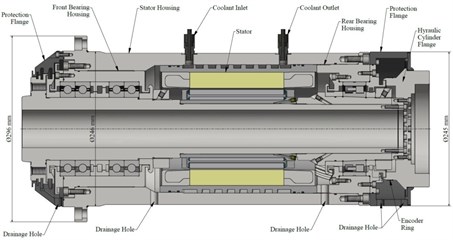
The MMS shown in Fig. 1 is presented to utilize the forced rotordynamic analyses, which it developed to built-in motor instead of traditional belt drive lathe spindle. This spindle has been developed for the chuck standard JIS A2-6/B6151sc, with maximum 3700 N cutting force, maximum 7000 r.p.m machining speed, and driven by the 16.8 kw synchronous motor connected to the shaft with a built-in-motor Type 1FE1093-6WV. Two kinds of SKF roller bearings with the designation of 7220BECBY, and NNCF5013CV are presented for supporting the shaft at front bearings set location, and back bearings set location. The materials used for this MMS is structural steel ( 210 GPa, 7850 kg/m and 0.3).
Fig. 1Machine motorized spindle system
2.1. Finite element model of machine motorized spindle system
The MMS exposing several loads under operation condition is established, including the rotating unbalance moment to the shaft from the motor rotor and constant cutting force. The FEM of the MMS is developed by using the ANSYS SpaceClaim. All the masses of motor-rotor and workpieces-holder (chuck) are modeled as a point mass and integrated into FEM at desired locations, with a Remote-Point-type connection. The bearing supports are modeled as 2-D spring damper elastic elements (COMBI214) with a ground-to-body-type bearing connection, as shown in Fig. 2.
Fig. 2Bearings support
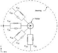
Fig. 3The FEM meshing for MMSshaft
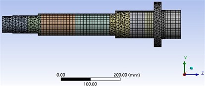
Two spring-damper elements for supporting the shaft at the front bearing set and so one spring-dampers element for supporting the shaft at back bearing set. With assuming that, the applied preloads on bearings are not influenced by their locations; the bearing stiffness defined in this study is 4E5 N/mm for the front bearing set and 2E5 N/mm for back bearings set. The entire spindle model has meshed via elements size of 10 mm, the 3D meshing of MMS is shown in Fig. 3.
3. Results and discussions
3.1. The unbalance response analysis
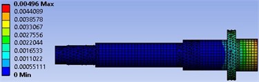
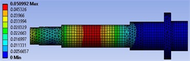
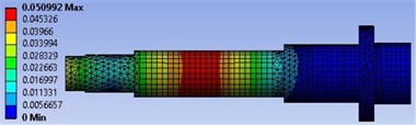
The forced Rotordynamic analysis is performed under two excitation conditions, first under only constant cutting force and second under both cutting and rotating unbalance forces excitation. The simulation is conducted with the 3700 N excitation cutting force applied in the -direction, and excitation rotating unbalance of 6 kg-mm, with excitation speed varied from 0 Hz to 400 Hz. The simulations results undercutting force, and with both cutting force and rotating unbalance excitations are shown in Fig. 4. It can be seen from Fig. 4(a), the maximum Total Deformation (TD) is 0.0496 mm, which it recorded at spindle nose; while the maximum TD in Fig. 4(b) is 0.0509 mm; which it takes place in the motor-rotor location. The results obtained for TD indicated that the spindle has extremely affected more by the rotating unbalance force excitation than the cutting force excitation.
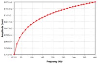
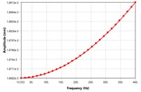
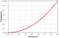
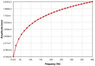
In order to visualize the effect difference excitation speed on unbalancing response, the four locations of the MMS as shown in Fig. 5 have been selected for vibration analyzes. From Fig. 5, it can be seen that; the vibration amplitude has been caused by the rotating unbalance in the MMS system. Among the four places, the vibration response at motor-rotor seat position is far greater than other places in the spindle system. Once the deformation amplitude of the MMS is growth, the dynamic stiffness is turns into lower. Thus, the minimum dynamic stiffness in Fig. 5 is found at motor rotor place, while the maximum dynamic stiffness is found at spindle nose position. As well, the vibration modes increased in a linear manner as the excitation frequency increase, which is relatively comparable to theoretical studies [3]. The vibration response reached its peak at 400 Hz excitation frequency. There is no vibration resonance recorded within the excitation frequency range, as result of damping effects. As mentioned above, the vibration of MMS is considerably influenced by the rotating unbalance due to motor-rotor, hence it’s significant to consider in FEM when conducting the vibration design.
Fig. 4Total deformation of the spindle: a) undercutting force excitation, b) under rotating unbalance mass and cutting force excitation
a)
b)
Fig. 5The vibration modes shape of unbalance response at different locations on the spindle: a) mode shape at rotor position, b) mode shape at spindle nose, c) mode shape at the front bearing location, d) mode shape at back bearing location
a)
b)
c)
d)
3.2. Sensitivities of factors on vibration of unbalance response
In this study, the FEM-based experiment has been carried out to simulate the vibration response and SW with the factors. The definition of the factors used in this experiment and their limits are shown in Table 1. The face-centered CCD due to its effectiveness in providing much statistics in a minimal number of required statistical experiments is used to create the DOE. The simulation result obtained is fitted by RS, and then it graphically explained in Fig. 6. It showed that the scatter chart presented is normalized with the output values predicted from the RS versus the value observed from the DOE. The goodness fit indicated that the TD and SW are normally closer; confirming that the RS is correctly fits the points of DOE.
Fig. 6The predicted response surface output versus observed from DOE
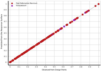
Table 1The constraints of design factors and their definitions
Factor limit | Definition |
[41, 55] | The spindle inner diameter at back bearing location [mm] |
[41, 60] | The spindle inner diameter at motor rotor location [mm] |
[54, 60] | The spindle inner diameter at front bearings location [mm] |
[10, 70] | The locations of back bearings set to the back end of the motor rotor [mm] |
[10, 60] | The locations of first front bearings set to the front end of the motor [mm] |
[20, 60] | The locations of second front bearings to the front end of the motor [mm] |
[7200, 7860] | Material density of the spindle [kg.m-3] |
[190, 210] | The material of the spindle [GPa] |
[600, 4000] | Cutting force [N] |
[0, 10] | Motor rotor unbalance mass [kg] |
3.2.1. The levels of factors affecting the unbalance response
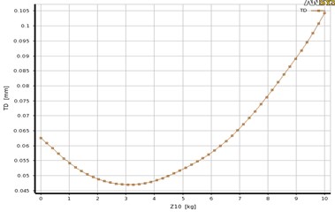
The sensitivities of the factors on TD and SW are analyzed by using Kriging RS method. The contribution of each factor on TD and SW is graphically represented in Fig. 7. From Fig. 7, it can be showed that a larger response ratio indicates that the corresponding factor has a more obvious influence on the output responses of TD (P1), and SW (P25). For the station P1shown in Fig. 7, the factors (45 %), (20 %), (18 %), and (11 %) have the most effective on TD, respectively; while the other factors have the least effects on the TD. For the station P25 shown in Fig. 7, the factors (50 %), (25 %), (15 %), and (12 %) have the most effective on SW, respectively; while the other factors have the least effects on the SW. As results, more than 40 % of vibration is conducted by rotating unbalance mass (), hence the rotating force excitation is far greater than cutting force excitation (). In order to visualize the effect of variation of rotating unbalance mass on the dynamic response, the change in TD with the factor is plotted as explained in Fig. 8. It can be seen from Fig. 8, the variation of TD with the factor is approximately nonlinear, which the TD improved/and or increased with increasing the factor space along its variation limits. The variation of vibration response with rotating unbalanced masses at different rotating speed has carried out in [3], they obtained that the dynamic response of the MMS is increased linearly with increasing the rotational speed, and so as rotating force increased.
Fig. 7The sensitivities of factors on the vibration of unbalance response
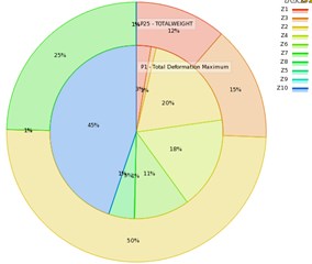
Fig. 8The effect change of rotating unbalance force on TD
3.2.2. Factors optimization
The definition of the optimization problem and its constraints are represented in Eq. (1). The optimization is defined to minimize the SW, with a maximum constraint of TD (0.067 mm). The Screening and Multiple-Objective Genetic Algorithm (MOGA) methods are used to solving this mathematical problem. The three optimal’ points for each method are suggested, and then they are summarized in Table 2. It can be observed that the optimal points in columns 3&7 of Table 2 are feasible solution that could meet the design requirements. Among them, based on cutting force criteria the design points in column 7 is most suitable in minimizing the SW with satisfying the dynamic stiffness requirements. Further, from the response points shown in Table 2 it found that there are significant improvements achieved for the TD and SW, when comparing the optimal design with the original value. It showed that the SW is saved by 16.8 %, while the TD is improved by 13.7 %. So as to find the dynamic behavior of the final design, the optimal response points are inserted into the FEM, and then it updated and resolved with this new design point. The new solution results are summarized in Figs. 9, 10 as a comparison with the original one. The results carried out indicated that the value of TD after optimization is comparable to its value in Table 2; hence the FEM has correctly updated the optimal design point.
Table 2The initial and optimal design for both screening and MOGA methods
Design variables | Initial design | An optimal candidate design points | Final design | |||||
Screening method | MOGA method | |||||||
[mm] | 42 | 50.065 | 47.125 | 54.895 | 41.93 | 54.658 | 51.8 | 51.8 |
[mm] | 42 | 59.905 | 56.204 | 55.118 | 58.97 | 58.655 | 53.9 | 53.9 |
[mm] | 54 | 58.803 | 56.782 | 50.307 | 58.09 | 59.050 | 57.8 | 57.8 |
[mm] | 50 | 43.649 | 40.078 | 43.361 | 32.92 | 42.377 | 41.7 | 41.7 |
[mm] | 50 | 13.678 | 46.713 | 28.913 | 20.50 | 49.146 | 38.6 | 38.6 |
[mm] | 50 | 38.695 | 42.194 | 50.140 | 32.31 | 24.923 | 56.3 | 56.3 |
[kg.m-3] | 7850 | 7759.1 | 7714.5 | 7335.2 | 7540.8 | 7846.9 | 7601.4 | 7601.4 |
[GPa] | 210 | 207 | 204 | 198 | 201 | 200 | 199 | 199 |
[N] | 3700 | 3677.6 | 3960.1 | 3149.7 | 3551.2 | 3418.56 | 3670.8 | 3670.8 |
[kg] | 6 | 1.4046 | 0.3641 | 1.6882 | 4.15 | 1.01 | 3.53 | 3.53 |
Response | – | – | – | – | – | – | – | – |
TD [mm] | 0.051 | 0.0654 | 0.0665 | 0.0651 | 0.0661 | 0.065 | 0.0650 | 0.0446 |
SW [kg] | 19.063 | 15.1 | 16.06 | 15.58 | 15.32 | 15.26 | 15.86 | 15.86 |
Also, it can be seen from Fig. 9(b), the maximum TD observed is 0.0446 mm at motor rotor position; which it improved to 13.7 % less than the original value shown in Fig. 9(a). Thus, the minimal weight design technique, not only satisfies saving in total material resource consumed, but also the vibration response characteristics can be improved. It confirmed the effectiveness of this method to come across the energy efficient design requirements in terms of energy consumption and material resources used and the waste and pollution created in the process:
Fig. 9The vibration mode with unbalance effect: a) initial design, b) optimal design
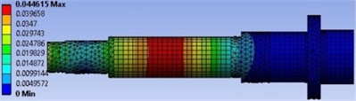
a)
b)
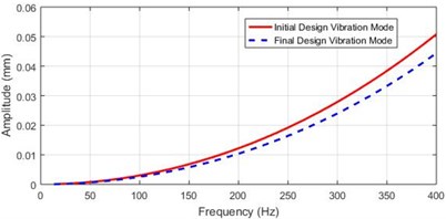
Fig. 10Comparing the vibration mode shape of the spindle at motor-rotor location
4. Conclusions
In this work, the vibration of MMS exposing several excitation forces is carried out using forced Rotordynamic analysis and the RS method. The results obtained showed that the vibration response is considerably influenced by the rotating unbalance force. Whereas, the vibration amplitude conducted by rotating unbalance force is more than 40 % when compared to the other factors. The results also showed that there are significant improvements achieved, hence the SW is saved by 16.8 %, and so the TD is improved by 13.7 %. The proposed dynamic design approach is significant and successful in improving vibration of unbalance response.
References
-
Didier J., Sinou J.-J., Faverjon B. Study of the non-linear dynamic response of a rotor system with faults and uncertainties. Journal of Sound and Vibration, Vol. 331, Issue 3, 2012, p. 671-703.
-
Larsen J. S., Santos I. F. On the nonlinear steady-state response of rigid rotors supported by air foil bearings – theory and experiments. Journal of Sound and Vibration, Vol. 346, 2015, p. 284-297.
-
Xul J., et al. Vibration characteristics of unbalance response for motorized spindle system. Procedia Engineering, Vol. 174, 2017, p. 331-340.
-
Lin C.-W., Tu J. F. Model-based design of motorized spindle systems to improve dynamic performance at high speeds. Journal of Manufacturing Processes, Vol. 9, Issue 2, 2007, p. 94-108.
-
Liu J., Chen X. Dynamic design for motorized spindles based on an integrated model. The International Journal of Advanced Manufacturing Technology, Vol. 71, Issue 12, 2014, p. 1961-1974.
-
Lin C.-W. An application of Taguchi method on the high-speed motorized spindle system design. Proceedings of the Institution of Mechanical Engineers, Part C: Journal of Mechanical Engineering Science, Vol. 225, Issue 9, 2011, p. 2198-2205.
-
Lin C.-W. Simultaneous optimal design of parameters and tolerance of bearing locations for high-speed machine tools using a genetic algorithm and Monte Carlo simulation method. International Journal of Precision Engineering and Manufacturing, Vol. 13, Issue 11, 2012, p. 1983-1988.
-
Feng H., Jiang S. Dynamics of a motorized spindle supported on water-lubricated bearings. Proceedings of the Institution of Mechanical Engineers, Part C: Journal of Mechanical Engineering Science, Vol. 231, Issue 3, 2016, p. 459-472.
-
Huang P., Lee W. B., Chan C. Y. Investigation of the effects of spindle unbalance induced error motion on machining accuracy in ultra-precision diamond turning. International Journal of Machine Tools and Manufacture, Vol. 94, 2015, p. 48-56.
-
Zhou J., et al. A rotor unbalance response based approach to the identification of the closed-loop stiffness and damping coefficients of active magnetic bearings. Mechanical Systems and Signal Processing, Vol. 66, Issue 67, 2016, p. 665-678.
-
Wu Q., et al. Effect of motor rotor eccentricity on aerostatic spindle vibration in machining processes. Proceedings of the Institution of Mechanical Engineers, Part C: Journal of Mechanical Engineering Science, Vol. 232, Issue 7, 2017, p. 1331-1342.
About this article

The authors gratefully thank the technical support that provided by College of Mechanical and Electrical Engineering, Northeast Forestry University, Harbin, China, during this work.
