Abstract
In this work, a control strategy is developed for a lower limb-assisted exoskeleton. To determine the current motion gait of the human body, the hip and knee joint angles, and plantar pressure values are sensed and analyzed, which are then used to actuate the exoskeleton to provide support for the hip and knee joints. The dual motion systems-the exoskeleton drive system and the human lower limb motion system-are established in this control approach. Without the need to first learn the user's gait, the assistance of the exoskeleton is provided by the motions of the human movement system and is sufficiently flexible to account for changes in step length and walking speed as the user moves through the gait cycle. Throughout this process, the exoskeleton system avoids providing power, providing the freedom to walk and stop in the course of our daily lives.
Highlights
- No need to enter motion gait in advance, compatible with daily walking
- Flexible driving according to the user's gait
- Start and stop immediately without additional operation
- Adapt to complex environments such as crowd
1. Introduction
Military and medical applications are the main uses for the assisted exoskeleton robots that are currently available on the market. The former can assist users in completing previously challenging tasks, while the latter can be used to help stroke victims who are hemiplegic regain their perception of body movement and reclaim lost motor function. Exoskeletal robots designed for civilian use must be more comfortable than those designed for use in the military or healthcare, which prioritize functionality. At the same time, the design of such exoskeletons needs to be able to practically break down metabolic cost barriers and ensure that the user conserves physical energy while completing the same routine movements compared with equipping an exoskeleton. Current hip, knee, and ankle-jointed assisted exoskeleton robots of all types are hot research topics.
The Gait Enhancing Mechatronic System (GEMS) help to reduce cardiometabolic energy expenditure when climbing stairs among the elderly [1]. The use of GEMS allows the elderly to climb stairs with less metabolic energy, so they may have more endurance when using GEMS. Huang proposed an adaptive sensitivity amplifier control strategy based on reinforcement learning for human-mechanical power enhancement exoskeletons [2]. Such studies, although they can achieve the goal of saving stamina, are currently mostly limited to laboratory environments, completed by treadmill tests with defined speeds, and are still a long way from actually being put to use in everyday life environments, due to their drawback of not being able to start and stop flexibly. Therefore, our study aims to validate a new driver strategy in which the user's movement on foot is no longer restricted by the motion of exoskeletons, and the user can then decide to move or stop at any time, breaking the restriction that assisted exoskeletons can only move in a laboratory setting.
2. Human lower limb modelling
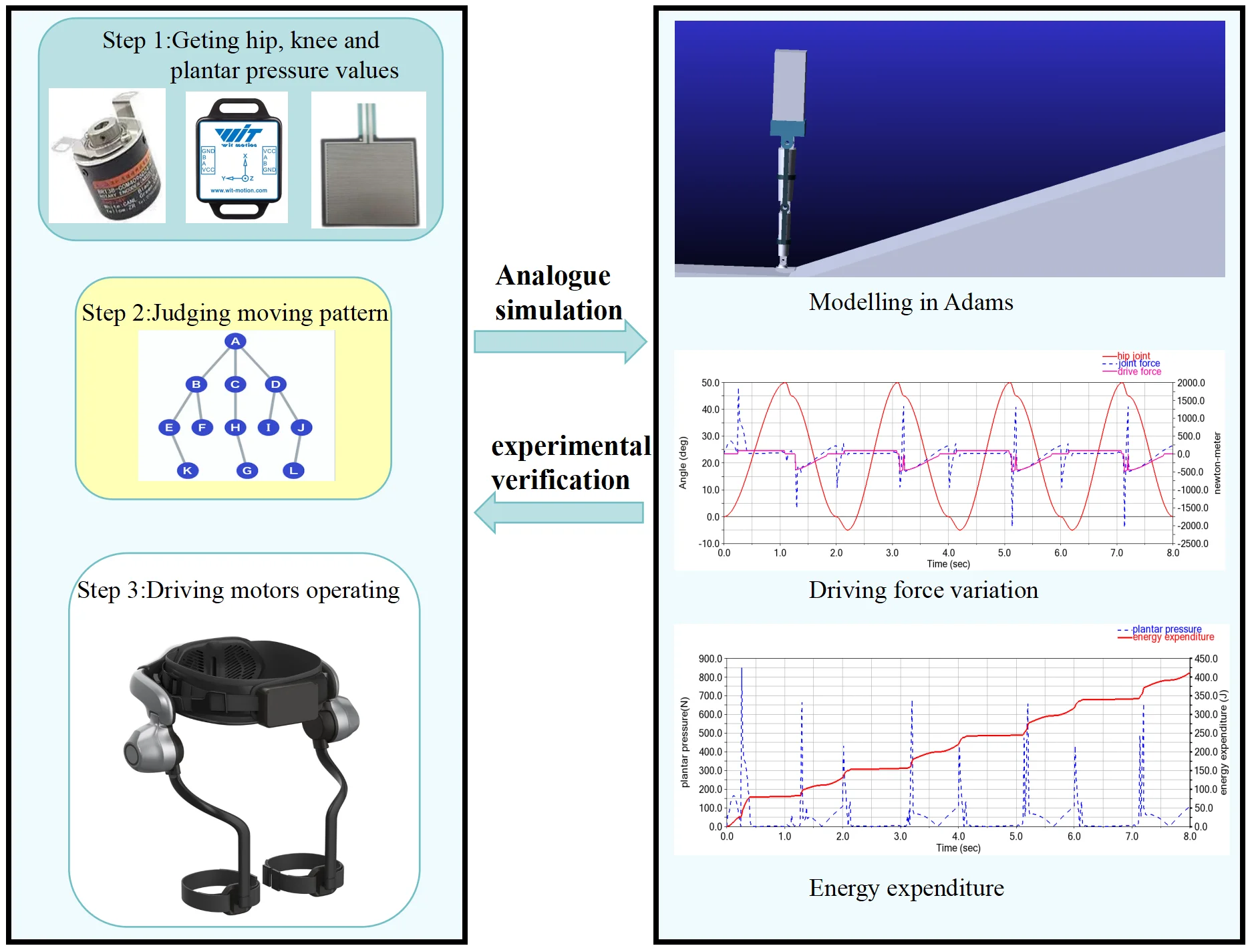
The control algorithm, as the key to the operation of the exoskeleton robot, determines the functionality and main performance of the robot. The control system is divided into three phases: sensing, decision-making, and execution [3]. For the purpose of exploring new motion control algorithms, the sensing and execution stages, which are susceptible to hardware devices, are not considered. The main objective of this paper is to provide a new pathway for decision-making, analyze its rationality, and obtain results by building a model through data graphs.
2.1. Design of the human lower limb model
The lower limbs of the human body are needed both to provide support for the body and to achieve spatial movement of the body. The bones and joints of the lower limbs form a locomotor mechanism, and the muscles attached to them provide the forces that maintain stability or achieve movement in this mechanism. Motor-driven joint movements are used as a substitute for muscle force, and the motor’s power change during operation is used to infer how much physical energy is used by the muscles during actual movement. The motion platform has not yet been built, and the experimental model is in the simulation validation stage. Firstly, a human lower limb motion model is established; the model is designed according to normal human lower limb proportions; a simple hip-knee-ankle joint motion is established; only the walking motion in the coronal axis direction is considered; and no other complex leg motion is considered. This was carried out using Adams simulation software.
The model is designed to perform simple walking movements consistent with biology and compute walking motion data of the human body. The unilateral human lower limb is generally approximated as a 7-degree-of-freedom multi-rigid tandem mechanism, as shown in Fig. 1, with the hip joint connecting the torso to the thigh with 3 degrees of freedom, the knee joint connecting the thigh to the calf with only 1 degree of freedom, and the calf to the foot connected by the ankle joint with 3 degrees of freedom. In order to focus on walking movements, the unilateral lower limb design was simplified to a tandem mechanism with three degrees of freedom, retaining only the three joints for extension and flexion. The aim is to ensure that the model only performs walking movements and to avoid the influence of other compound movements on the experimental results.
Fig. 1Joint flexibility
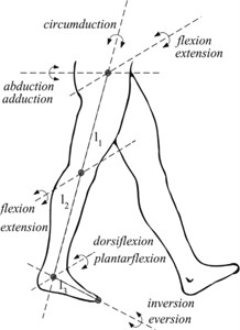
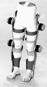
Fig. 3The prototype and mechanism schematic
2.2. Human lower limb model walking experiments and results
The dimensions were selected using a simplified 3D model of the human body based on an approximate 70 kg and 1.70 m height. The masses were set according to the laws of human body weight distribution. The length of the thigh is 50 cm, the calf is 40 cm, and the foot is 10 cm. The weight distribution is shown in Table 1.
The lower limb motion gait was designed to follow the biomechanical properties of human lower limb motion, making the motion as close as possible to a real walking state, with the pace set at 60 steps per minute.
The current bionic motion control of bipedal robots is still at the forefront of popular research and is a long way from restoring human motion. There are still major drawbacks to the motion of current bipedal robots, chief among which is the difficulty of maintaining good balance in both motion and rest. As the balance of movement is too complex and not the focus of this paper, in order to avoid the failure of the lower limb model movement due to interference with the balance problem, constraints are added to the torso part of the model to help maintain a stable state and ensure that the model is only affected by gravity and ground friction during the movement.
To determine changes in left hip, knee, and ankle joint angles as well as foot-to-ground contact forces. Movement patterns are found by analyzing the data. Patterns of movement are found by analyzing the data. Subsequent experiments can be conducted to obtain new walking states by varying the stride length and speed as a means of verifying the compatibility of the exoskeleton system in complex situations where a change of walking state occurs.
Table 1Weight of each body part
The whole body | Head | Trunk | Arm | Thigh | Calf | Foot | |
Percent (%) | 100 | 8 | 50 | 5 | 10.1 | 4.4 | 1.5 |
Weight (kg) | 70 | 5.6 | 35 | 3.5 | 7.07 | 3.08 | 1.05 |
2.3. Individual motion simulation of the lower limb model
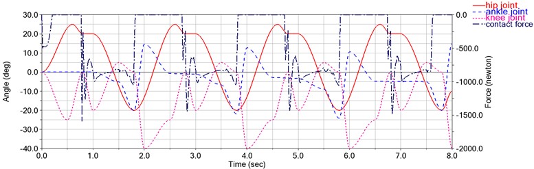
The motion simulation of the lower limb model was carried out by Adams simulation software to obtain the change in the hip, knee, ankle joint angles and contact force between the foot and the ground. Taking the left joint of the body as an example, the motion data is shown in Fig. 2.
Philippe Malcolm found that ankle-assisted robots were more advantageous in flat walking movements [4]. However, the hip and knee exoskeleton robots are more advantageous in uphill or stair climbing movements [5], which are less physically demanding and rely on the lower leg for power. However, considering the high flexibility and low stability of the ankle joint and the fact that the walking angle is easily influenced by the ground environment, it is difficult to budget the state of its movement in complex environments, and because it is at the end of the body, the need for assistance is relatively small, so the design does not consider the motion assistance of the ankle joint, and the subsequent motion analysis does not consider the movement state of the ankle joint.
Fig. 2The change in the hip, knee, and ankle joint angles and contact force on flat ground
3. Design of the lower limb model of the exoskeleton
3.1. Design of structures
In the control system of the exoskeleton robot, an accurate kinematic and dynamic model of the system is required to complete the modelling of the human-machine control system and to achieve effective control of the human-machine system. The prototype and schematic of the mechanism for the proposed lower limb exoskeletal robot are shown in Fig. 3.
3.2. Analysis of the motion scheme
The aim of this control method is to avoid the important control problems of current exoskeleton robots:
1)The problem of a single locomotor pace Nowadays, a large number of exoskeleton robots need to detect the user’s movement pace in advance to obtain the final paces movement data through data processing [6]. Although these data can control the exoskeleton robot to complete the assertive behavior, due to the complexity of the individual, the walking pace will change during a period of walking due to various intrinsic or extrinsic reasons, such as personal mood, weather, ground conditions, and external interference. When the gait of the exoskeleton is not perfectly matched to the user, it creates interference and resistance for the user, who needs to overcome these obstacles, which also causes additional physical exertion.
2) The problems of inflexible start and stop. As exoskeleton robots require direct contact with the human body, their safety must be guaranteed, which is currently based on verifying that the bending angle of each joint does not exceed the maximum acceptable for the human body. One of the reasons why currently powered exoskeleton robots can only be used in laboratory environments and cannot be adapted to everyday complex environments is because safety cannot be guaranteed. The most important feature of walking in an outdoor environment is the uncontrollable nature of the environment, which requires the flexibility to switch between walking and standing. Although exoskeletons exist that can switch between states, this can be done with additional movements and cannot be done by stopping the leg muscles from acting like a human.
3.3. Motion-assisted design
By observing joint movements and ground contact forces and combining kinematic rules with daily walking gait, the hip and knee movement patterns are found to drive the exoskeleton to provide support:
1) Using the left leg as an example, when the hip joint bends (knee forward) at a smaller angle than the knee joint (when viewed from the left side, with the ankle joint as the origin and the lower leg in the second quadrant), the leg will tend to lift and the hip joint will continue to bend, at which point the hip joint is required to produce a steady movement.
2) Based on the premise of (1), the lower leg moves forward under the influence of the thigh swing, crossing the positive half-axis of the -axis and moving into the first quadrant, stopping the hip joint’s power drive, and causing the left leg to fall naturally as the body’s center of gravity moves forward;
3) On the basis of (2), when the contact force between the left foot and the ground is greater than 0.1 MG, detect the hip and knee bending angles. If the hip bending angle is greater than 5° (e.g., 20°) and the knee bending angle is less than 5° (the body is walking on flat ground), the hip joint drive starts to power up, the knee joint power up is not available, making the hip bending angle smaller, stop when the hip bending angle is less than 5°, and at the same time the center of gravity falls on the left foot;
4) On the basis of (3), the left leg is upright on the ground; when the center of gravity falls on the left foot, the right lower leg is located in the second quadrant; the contact force between the right foot and the ground is reduced; the right leg will repeat the movement of (1) and continue walking;
5) On the basis of (2), when the contact force between the left foot and the ground is greater than 0.1 MG, detect the hip and knee bending angles. If the hip bending angle is greater than 5° (such as 40°) and the knee bending angle is greater than 5° (such as 40°, the body presents climbing movement), the hip and knee drive begins to boost, so that the hip and knee bending angles are smaller, while the body weight falls on the left foot and begins to move up. When the hip joint angle is less than 5°, stop. The right leg drops naturally during this process, and the subsequent movement repeats (1), continuing to walk.
The above summary of the law is only derived from observation and projection and has not been tested on the actual platform. The individual angles and contact forces (e.g., 0.1 mg, 5°, or quadrant angles) are tentative values that are in error with the actual data and can be optimized through experimentations in the future.
4. Experiments and analysis
4.1. Hip joint alone assisted walking simulation
A hip-joint exoskeleton robot was installed in the motion model. The motion model maintains the original motion movement, and the exoskeleton robot will provide the driving force according to the motion movement, as shown in Fig. 4(a), which proves the feasibility of this driving method. However, due to the shortcomings of the model building, such as the fact that the contact point between the model and the ground cannot be set, the lack of cushioning and excessive instantaneous impact force of the contact leads to the vibration of the model, which cannot fully simulate the human motion, the torque change of the hip joint is not smooth enough, and the deviation is too large. At the same time, there was no significant decrease in the energy consumption of the model hip joint when walking on the flat ground due to the gravity of the exoskeleton robot.
Fig. 4Co-simulation of the lower limb and exoskeleton robot
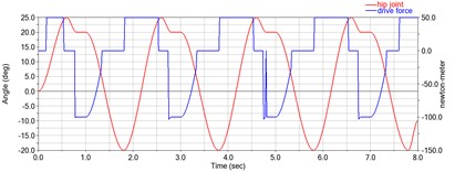
a) Hip joint booster on flat ground
b) The change in the hip, knee ankle joint angles and contact force on the slope
c) Hip joint booster on the slope
d) Hip joint booster on the slope
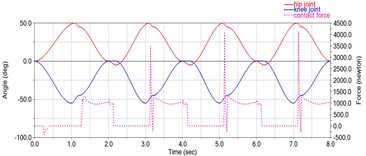
4.2. Hip and knee joint-assisted walking simulation
Since the effects of the hip-assisted movement were not evident when walking horizontally, a climbing session was added to the experiment, in which changes in torque between the front and back of the hip and knee were compared using hip and knee exoskeletal drives.
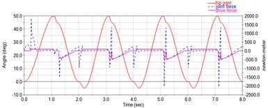
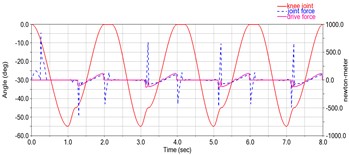
The main difference is that previous studies examined horizontal walking, whereas the present study was conducted during hill climbing, which requires approximately 20-30 % more cardio-metabolic energy than horizontal walking [7], [8]. The model data were held constant, the ground environment was adjusted to a slope with an inclination angle of 20°, and the exercise model was performed bottom-up for climbing movements, disregarding errors due to friction, slippage, and other disturbances. The simulation data is shown below. Fig. 4(b) shows the relationship between the bending angle of the left hip and knee joints and the contact force between the left foot and the ground over time during the motion. Fig. 4(c) shows the driving torque of the hip joint during the movement and the moment of rotation of the hip joint when there is no driving. Fig. 4(d) shows the driving torque on the knee joint and the moment of rotation of the knee joint without drive during locomotion.
It can be seen from the graphs that the change in the angle of the hip and knee joints during the movement of the model is relatively smooth, but the abrupt change in the foot contact force and joint torque is too large and does not correspond to the actual human movement, so it is not possible to verify the effectiveness of the control method simply by comparing the data. However, by observing that the direction of the angle change is the same as the direction of the booster, the effectiveness of this control method can be proven. At the same time, the trigger of the booster drive does not depend on time, but on the user's movement. Current booster data show a 19 % reduction in hip consumption and a 13 % reduction in knee joint consumption. Further studies will be conducted to optimize data based on the results of the study, either by establishing or using existing platforms.
5. Conclusions
In this study, we propose a novel drive approach for powered exoskeleton robots that has the potential to solve the problem of exoskeleton robots currently used only in laboratory environments. This method avoids the current common method of motion control, which is to determine the motion path by entering the motion path in advance. Users need to actively adapt to the exoskeleton robot's motion trajectory to obtain a boost. It predicts the user’s current walking posture by measuring the force of the foot and the angle of the joint and provides appropriate assistance. Users can change their walking patterns during exercise, such as walking speed, leg lift height, or even stop standing, as they wish. This control method allows users to start and stop at will while on movement, greatly increasing the user's autonomy and enabling better adaptation to complex everyday environments, including crowded environments, as well as better security.
In contrast to other powered exoskeleton robots where the drive is actuated throughout the work process, this method of control uses a half-way drive strategy, where the drive is boosted for a series of movements that require more physical exertion in order to elevate the legs and the body’s center of gravity, such as leg raising and stepping, and not for other motions that are primarily gravity-driven, thus saving the robot’s energy consumption.
References
-
D.-S. Kim et al., “A wearable hip-assist robot reduces the cardiopulmonary metabolic energy expenditure during stair ascent in elderly adults: a pilot cross-sectional study,” BMC Geriatrics, Vol. 18, No. 1, p. 230, Dec. 2018, https://doi.org/10.1186/s12877-018-0921-1
-
Rui Huang, Hong Cheng, Qiming Chen, Huu-Toan Tran, and Xichuan Lin, “Interactive learning for sensitivity factors of a human-powered augmentation lower exoskeleton” in IEEE/RSJ International Conference on Intelligent Robots and Systems (IROS), pp. 6409–415, 2015.
-
Xing et al., “Research situation and development trend of robot exoskeleton,” Chinese Medical Equipment Journal, Vol. 36, No. 1, pp. 104–7, 2015.
-
P. Malcolm, W. Derave, S. Galle, and D. de Clercq, “A simple exoskeleton that assists plantarflexion can reduce the metabolic cost of human walking,” PLoS ONE, Vol. 8, No. 2, p. e56137, Feb. 2013, https://doi.org/10.1371/journal.pone.0056137
-
M. K. Maclean and D. P. Ferris, “Energetics of walking with a robotic knee exoskeleton,” Journal of Applied Biomechanics, Vol. 35, No. 5, pp. 320–326, Oct. 2019, https://doi.org/10.1123/jab.2018-0384
-
D. F. N. Gordon, C. Mcgreavy, A. Christou, and S. Vijayakumar, “Human-in-the-loop optimization of exoskeleton assistance via online simulation of metabolic cost,” IEEE Transactions on Robotics, Vol. 38, No. 3, pp. 1410–1429, Jun. 2022, https://doi.org/10.1109/tro.2021.3133137
-
J. D. Knaggs, K. A. Larkin, and T. M. Manini, “Metabolic cost of daily activities and effect of mobility impairment in older adults,” Journal of the American Geriatrics Society, Vol. 59, No. 11, pp. 2118–2123, Nov. 2011, https://doi.org/10.1111/j.1532-5415.2011.03655.x
-
K. H. Cho et al., “Energy expenditures for activities of daily living in Korean young adults: a preliminary study,” Annals of Rehabilitation Medicine, Vol. 40, No. 4, pp. 725–733, 2016, https://doi.org/10.5535/arm.2016.40.4.725
About this article

The authors have not disclosed any funding.
The datasets generated during and/or analyzed during the current study are available from the corresponding author on reasonable request.
The authors declare that they have no conflict of interest.
