Abstract
As part of this study, an ankle rehabilitation device was developed for patients suffering from motor disorders caused by incomplete spinal cord injury (ISCI), stroke, or cerebral palsy. First, the research models and dynamic equations of the device were considered. Secondly, the prototype ankle rehabilitation device is made of PLA plastic and uses linear actuators to simulate outward and inward flexion exercises (dorsiflexion and plantar flexion) for the patient. The advantages of the device are its simple design, low cost, and the possibility of installation on recovery equipment. The device can work quickly in experiments, in addition, the rehabilitation robot can work stably and is convenient to use for patients.
Highlights
- The novelty of this study lies in the integration of electrically linear actuators within the AlmAnkleExo, a novel ankle exoskeleton developed by the authors.
- Unlike conventional exoskeleton designs that often rely on pneumatic or hydraulic systems, the utilization of electrically linear actuators represents a significant departure from established approaches.
- This innovation enables precise control over three degrees of freedom in the lower leg, namely dorsiflexion/plantarflexion, inversion/eversion, and pronation/supination, thereby facilitating more natural and efficient movement.
- The unique aspect of employing electrically linear actuators lies in their inherent advantages, including enhanced control precision, reduced energy consumption, and simplified maintenance requirements.
- This departure from traditional actuation methods opens new possibilities for wearable robotics, particularly in the realm of lower limb rehabilitation and augmentation.
- This structured presentation aims to convey a holistic understanding of the device, encompassing its design, theoretical foundations, and empirical validation through experimentation.
1. Introduction
The ankle joint plays a fundamental role in supporting, balancing, and facilitating movement in the human body. Formed by several articulations, the ankle joint connects the lower leg to the foot, with its primary function being dorsiflexion during foot elevation and plantarflexion during foot descent [1].
Many individuals suffer from problems with the ankle joint, which can be caused by simple factors or indicate more serious issues. Issues affecting the ankle joint area include strains or injuries, arthritis, osteoarthritis, rheumatism, neurological problems, and others. Improving ankle joint movements can help the joint surfaces become healthier, reducing pain. These issues may necessitate ankle joint rehabilitation.
Rehabilitation robots are essential in therapy due to their wide-ranging applications and demanding professional standards. As many ankles joint rehabilitation movements involve repetitive actions, there's a burgeoning development of robots tailored for this purpose. Traditional rehabilitation methods often demand extensive therapist involvement over prolonged periods. Thus, the design and creation of robotic exoskeletons for intensive, personalized, and cost-effective physiotherapy, especially for stroke survivors, are pivotal. These devices aim to empower patients to regain mobility and independence, enabling them to participate in social activities autonomously [2-3].
The use of robotic structures can bring benefits such as cost reduction in active labor for motion-based rehabilitation procedures and an expanded range of exercises, helping patients maintain mobility through continuous therapy [4-8]. The use of rehabilitation robots during post-stroke rehabilitation is limited due to high costs, and they are often considered too expensive for healthy systems.
This article introduces the AlmAnkleExo, a novel ankle rehabilitation device featuring electrically linear actuators for precise control over dorsiflexion and plantar flexion movements. Unlike traditional pneumatic or hydraulic systems, this device offers enhanced control precision, reduced energy consumption, and simplified maintenance. The integration of electrical linear actuators enables control over three degrees of freedom, enhancing natural movement. The article outlines the device’s design, theoretical foundations, and experimental validation, providing insights into its performance and functionality in lower limb rehabilitation.
2. Materials and methods
2.1. Kinematic characteristics
In designing rehabilitation devices for the ankle joint, it's essential to consider the joint's three degrees of freedom, enabling movement in the sagittal, frontal, and transverse planes. These correspond to dorsiflexion/plantar flexion, inversion/eversion, and pronation/supination, respectively. Understanding these degrees of freedom informs the design of devices like the ankle rehabilitation prototype discussed earlier, ensuring accurate replication and facilitation of the joint's movements. Technical specifications for such a robot are derived from anatomical data of the human ankle joint, ensuring alignment with physiological requirements [9].
The ankle joint can perform three different movements:
1) dorsiflexion/plantarflexion.
2) abduction/adduction.
3) inversion/eversion.
Dorsiflexion: Dorsiflexion involves bringing the foot upwards towards the anterior surface of the leg. This movement has a range of motion of up to 20 degrees. Muscles responsible for dorsiflexion include the tibialis anterior, extensor hallucis longus, extensor digitorum longus, and fibularis tertius.
Plantar flexion: Plantar flexion is the opposite movement of dorsiflexion, occurring when the toes are in contact with the ground and the heel is raised off the ground. The range of motion in plantar flexion ranges from 40 to 50 degrees. Muscles involved in plantar flexion include the gastrocnemius, soleus, and plantar muscles.
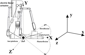
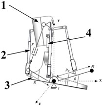
Fig. 2(а) shows a kinematic model of the AlmAnkleExo rehabilitation device, in this case, the foot drive mechanism uses a platform for the patient’s feet at 50 deg. turns up. 𝜃 the angle of rotation depends on the exercises of flexion of the foot joints, dorsiflexion at angles 0°20° and plantar flexion at –30° 0°.
Fig. 1Movement of the human ankle joint

2.2. Dynamic equations of the device
Establishing dynamic equations for each component of the device is crucial for understanding its interaction with patients' joints, aiding in mechanical design improvements and control system adjustments tailored to patient needs. In this study, dynamic equations were formulated using the Lagrange method, simplifying the process by assuming the total mass for both the human foot and foot platform. The torque required for ankle joint movement, is produced by the electric linear actuator.
Fig. 2(b) illustrates the dynamic diagram, where the actuator generates force on the foot platform connection, creating the necessary torque to rotate the platform and simulate ankle joint movement.
Fig. 2a) Scheme of the device for rehabilitation AlmAnkleExo; b) dynamic circuit of the device: 1 – shank platform, 2 – electric linear actuator, 3 – foot platform, 4 – ball joints
a)
b)
The Kinetic energy of an electric linear actuator:
The Potential energy of an electric linear actuator:
Lagrange function for the foot drive mechanism from Eqs. (1) and (2):
Dynamic drive mechanism equation based on Euler-Lagrange equations:
When the device is in operation, factors such as the weight of the components and the force applied to the patients affect the operation of the device:
where: ; , 𝐷 – coefficient of friction resistance of the platform, – the moment of numbness (the moment that occurs from the action of a person’s foot), 𝑀 – the mass of the foot and foot platform of a person, 𝑅𝐶– the length of the platform of the foot.
Therefore, angular acceleration can be obtained directly from the dynamic Eq. (5). The equation is then rewritten as:
3. Experimental platform
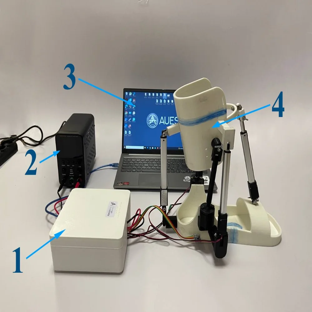
The use of electric linear actuators reduces our costs, providing a high potential for the correct implementation of the ankle joint to rehabilitation devices. The complete prototype of the presented ankle rehabilitation device is shown in Fig. 3.
Fig. 3AlmAnkleExo device: 1 – control unit, 2 – power unit, 3 – PC, 4 – AlmAnkleExo
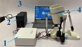
Fig. 4 and 5 show the scheme and structural scheme of the AlmAnkleExo device. First, the operator sets the angles of rotation of the device through the computer.
The device utilizes an Arduino Uno microprocessor to process sensor data and control linear actuators, enhancing precision and adaptability in ankle rotation. Key components include two L298N drivers for motor control and an ACS712 current sensor for real-time monitoring of current consumption. This integrated control unit enables dynamic adaptation to user needs, optimizing rehabilitation efficacy by finely tuning exoskeleton behavior to individual biomechanics.
Fig. 4A conceptual design for a lab prototype of the AlmAnkleExo
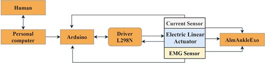
Fig. 5Structural diagram of the AlmAnkleExo device
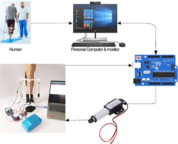
Table 1Device settings
Name | Type | Main parameters |
Electric linear actuator | L16-100-63-12-P 19 | DC12V |
Driver | L298N 2A | 5 V |
Current sensor | Sparkfun Resistive sensor | – |
EMG sensor | EMG Muscle Sensor V3.0 Module | 5 V |
Control board | Mega 2560 23 | 7-12 V |
4. Test results
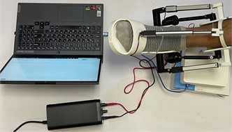
The experiment in this study was carried out on a man weighing 90 kg and 178 cm tall (Fig. 6). The device simulated dorsiflexion and plantar flexion at angles like SolidWorks simulations in previous studies [9-11] because it involved a range of human ankle movements.
Fig. 6The ankle rehabilitation robot prototype used for the Proof of Concept (PoC) experiments
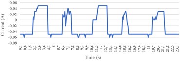
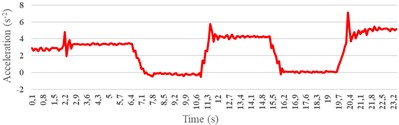
The ankle joint’s ability to dorsiflex and plantarflex depends on factors such as joint anatomy, ligament integrity, and muscle strength and flexibility. Fig. 7(a) depicts the power consumption profile of an electric linear actuator during experimental trials simulating dorsiflexion and plantarflexion movements. Recorded data indicates a maximum current consumption of approximately 50 mA required to drive the actuator's motion. Fig. 7(b) delineates the gradual acceleration profiles of dorsiflexion and plantar flexion exhibited by the prototype, expressed in terms of the angular displacement from the horizontal resting position at both 0 and 6 degrees.
Fig. 7a) AlmAnkleExo device received current consumption by electric linear actuators; b) AlmAnkleExo device acquired angular acceleration of the foot platform.
a)
b)
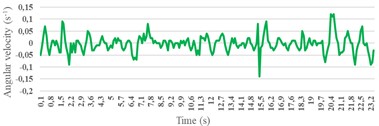
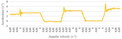
Fig. 8(a) illustrates the angular velocity profile of the exoskeleton. Within a 24-second interval, the upper portion exhibits a velocity of 0.1 rad/s, while the lower portion registers a velocity of -0.15 rad/s. Noteworthy on the graph are discernible noises and peaks, potentially attributable to backlash and assembly tolerances in the device. Despite these observations, the associated values remain within reasonable limits, demonstrating a relatively smooth transition between states. Fig. 8(b) portrays the angular velocity dynamics of the prototype during dorsiflexion and plantar flexion, revealing an angular velocity of approximately 6 rad/s in the upper part and -1 rad/s in the lower part. This depiction serves to characterize the rotational speed of the prototype across the specified movements, offering quantitative insights into the system’s performance during dorsiflexion and plantar flexion.
The motion test, deliberately conducted at a slow pace over approximately 24 seconds, aimed to simulate rehabilitation exercises, demonstrating the viability of the current cost-effective prototype for such applications. Insights gained from this intentional slow-motion test shed light on the device's performance in mimicking controlled and deliberate movements relevant to rehabilitation. Despite its economic viability, the study's limitation lies in its focus solely on healthy individuals, limiting generalizability, especially concerning stroke patients. Future research should broaden the scope to include stroke patients to better understand the intervention's effectiveness and feasibility across diverse populations, emphasizing caution in extrapolating outcomes to different health profiles.
Fig. 8a) AlmAnkleExo device angular velocity; b) AlmAnkleExo device acceleration
a)
b)
5. Conclusions
This article presents a kinematic model for a specialized ankle joint rehabilitation device, resulting in a fully functional prototype. Key findings include rapid response time, minimal angular error, and safe operation during human trials, validating its capability to follow predetermined trajectories. The device's simple structure enhances smooth functionality and adaptability to various parameters, showing promise for aiding stroke patients. Future research aims to refine the design and conduct comprehensive tests with actual patients, advancing its potential for clinical rehabilitation. These encouraging results warrant further exploration and development of the device for potential clinical applications.
References
-
R. S. Gonçalves, L. A. O. Rodrigues, R. Humbert, and G. Carbone, “A user-friendly nonmotorized device for ankle rehabilitation,” Robotics, Vol. 12, No. 2, p. 32, Feb. 2023, https://doi.org/10.3390/robotics12020032
-
D. Shi, W. Zhang, W. Zhang, and X. Ding, “A review on lower limb rehabilitation exoskeleton robots,” Chinese Journal of Mechanical Engineering, Vol. 32, No. 1, pp. 1–11, Aug. 2019, https://doi.org/10.1186/s10033-019-0389-8
-
Y. Jin, P. K. Jamwal, R. Goecke, M. H. Ghayesh, and S. Hussain, “Design and analysis of a multi-DOF compliant gait rehabilitation robot,” Mechanics Based Design of Structures and Machines, pp. 1–26, May 2023, https://doi.org/10.1080/15397734.2023.2215855
-
D. Pinto et al., “Budget impact analysis of robotic exoskeleton use for locomotor training following spinal cord injury in four SCI Model Systems,” Journal of NeuroEngineering and Rehabilitation, Vol. 17, No. 1, pp. 1–13, Jan. 2020, https://doi.org/10.1186/s12984-019-0639-0
-
R. S. Gonçalves, L. A. O. Rodrigues, R. Humbert, and G. Carbone, “Development of a nonmotorized mechanism for ankle rehabilitation,” IECMA 2022, Vol. 24, No. 1, p. 19, Sep. 2022, https://doi.org/10.3390/iecma2022-12899
-
Bogdan Gherman, “On the singularity-free workspace of a parallel robot for lower-limb rehabilitation,” Proceedings of the Romanian Academy, Series A, Vol. 20, No. 4, pp. 383–391, 2019.
-
D. Pisla et al., “Development of a control system and functional validation of a parallel robot for lower limb rehabilitation,” Actuators, Vol. 10, No. 10, p. 277, Oct. 2021, https://doi.org/10.3390/act10100277
-
I. Doroftei, C.-M. Cazacu, and S. Alaci, “Design and experimental testing of an ankle rehabilitation robot,” Actuators, Vol. 12, No. 6, p. 238, Jun. 2023, https://doi.org/10.3390/act12060238
-
Z. Nursultan, M. Ceccarelli, and G. Balbayev, “Design and performance analysis of ankle joint exoskeleton,” in Mechanisms and Machine Science, Vol. 133, Cham: Springer Nature Switzerland, 2023, https://doi.org/10.1007/978-3-031-32446-8_17.
-
Z. Nursultan, M. Ceccarelli, and G. Balbayev, “Design of an exoskeleton for rehabilitation ankle joint,” in Proceedings of SYROM 2022 and ROBOTICS 2022, pp. 219–227, Apr. 2023, https://doi.org/10.1007/978-3-031-25655-4_23
-
Z. Nursultan, A. Titov, M. Ceccarelli, and G. Balbayev, “Design and performance of a motion-assisting device for ankle,” in Advances in Asian Mechanism and Machine Science, pp. 659–668, Dec. 2021, https://doi.org/10.1007/978-3-030-91892-7_63
About this article

This research has been funded by the Ministry of Science and Higher Education of the Republic of Kazakhstan, Grant No. AP13268857.
The datasets generated during and/or analyzed during the current study are available from the corresponding author on reasonable request.
The authors declare that they have no conflict of interest.
