Abstract
A mathematic model of flexible rotor for the backward rolling with slipping on compliant stator and an exception concept for the contact forces are suggested. Dynamic characteristics for the rotor whirling are determined by the matrix methods. The whirl velocity can be calculated accurately, not only in case of a clear rolling when it is determined by the rotary velocity and a ratio of rotor radius at the contact place to radial clearance, but also in case of the backward slipping. It is shown for the second or whip case, the whip velocity is defined by some eigenfrequency of the supported rotor by the stator as well as by coefficients of the structural and contact friction. And in fact, the friction sets the whip frequency, and the -th eigenmode of contactless system sets the whip amplitude (rotor deflections outside the contact place).
Highlights
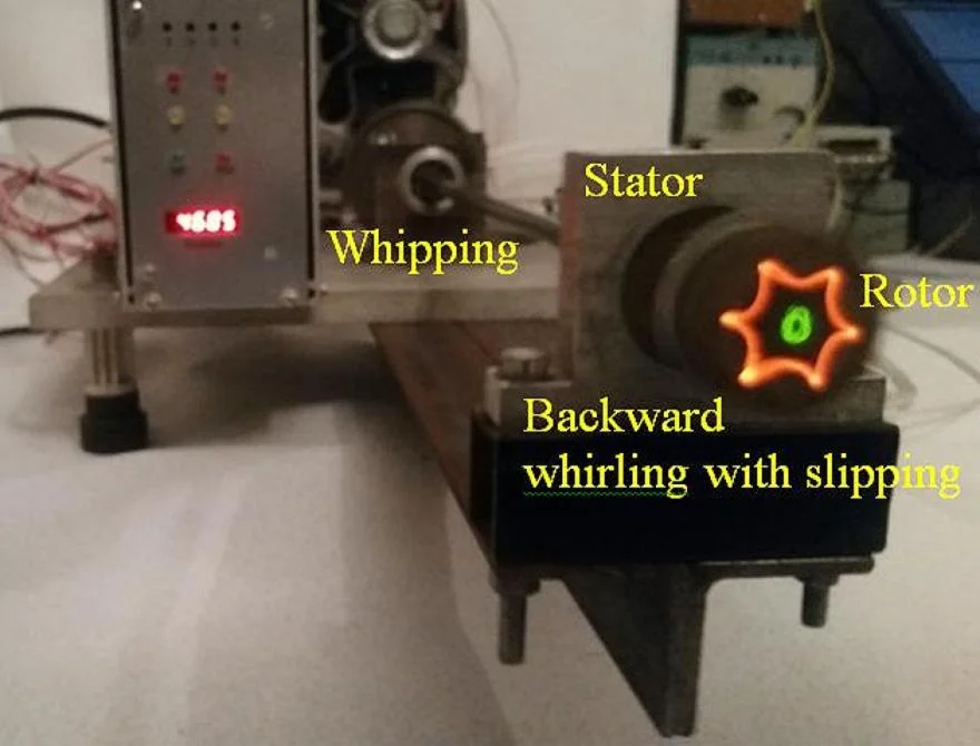
- Rolling of rotor on stator = backward whirling
- Backward slipping of rotor on stator = backward whirling with whipping of rotor
- Angular speed and whip amplitude of backward slipping are calculated values now
1. Introduction
The most of problems in an engineering practice associated with the shaft or rotor vibration is due to destructive effect of the stator on system. Originality of this work is that to determine forces of the normal pressure and dry or semi-dry friction arising at the contact, using harmonic displacements, velocities and accelerations (i.e. the normal oscillations equation) of the equivalent flexible rotor – compliant stator system. It is considered the flexible rotor – elastic bearings – foundation system briefly called original rotor system and also the flexible rotor – elastic bearings – rigid stator – elastic supports – foundation system which is simply called original rotor – stator system. In called the equivalent system the direct contact between flexible rotor and compliant stator is represented as an additional linear elastic coupling (spring between them) by the contact stiffness . Moreover, and the dynamic parameters of the equivalent system, called the parameters of contact system, and the dynamic characteristics of the original system without the explicit contact between rotor and stator, called the characteristics of contactless system, are actively used.
Previously researchers defined the contact forces either by a dynamics of the flexible rotor upon the rigid stator [1-4] or by the stiffness and damping of compliant stator [5-13] with the normal reaction at the contact location as a linear [5-9] or nonlinear [10-12] or generalized hysteresis looped characteristic [13]. In the latter work both the stator deformation and its direction and also a plastic effect for the loading-unloading path are taken into account. In some works [9-12] the stator compliance includes displacements of the stator on elastic-damper supports.
The proposed models with the rigid stator do not allow investigating the operation of stator displacements as an elastic and solid body as well as the vibroimpact motions of the system on basis of the ordinary differential equations.
Disadvantages of the models with given elastic-dissipative stator characteristic are empirical or theoretical coefficients. For example, in the widely used modified Hertz model with the viscous component and the sticking elimination and the recovery coefficient which is independent from the bodies approach velocity , where , , parameter const depends on the bodies materials and shape of their surfaces in the contact region, parameter const determines the value of recovery coefficient. In such models a problem of reliable obtaining of the contact-dynamic characteristics for the system arises, in particular, relatively the maximum accelerations of rotor. From here one should pay special attention to a correctness analysis on the definition of elastic component for the stator characteristic and to achieve an acceptable accuracy for the adopted model by selecting of the viscous component. Incorrect selection of the viscoelastic parameters can lead to physically incorrect results, for example, the value of recovery coefficient is greater than one.
2. Reaction of axisymmetric flexible rotor – compliant stator system due to contact
System Eq. (1) or (2) of the author’s paper [14] with a matrix order or or or can be directly used to determine a response of the whipping rotor to contact forces. Let the right-hand members of the matrix Eqs. (1) or (2) are only contact forces applied to the -th point of the original system (Fig. 1) and cause a regular (circular and steady) whirling or whipping:
Mathematical transformations will be more compact if beginning is from the matrix Eq. (2):
where , the or indexes are omitted.
Obviously, this is the standard finite element formulation for the rotor-stator system. The original rotor upon bearings is a combination of three finite elements (rigid disk, beam element and linearized viscoelastic support) which is loaded with concentration (at the -th point) by the forces of normal pressure and dry friction .
However, the force (boundary) condition at the contact point is ambiguous. It can be of any kind: rigid or elastic, linear or non-linear, pointed or deconcentrated on an area, with dry or semi-dry friction. Therefore, there is a need for a physical transformation (method) that would allow a priori unknown contact forces of the original system to be excluded from consideration.
Fig. 1Displacements of the k-th node original (blue) and the i-th node equivalent (red) flexible rotor – compliant stator system, contact forces of normal pressure N and dry friction T=μN, μ=tanγ, projections of the forces which load the original system and their resultant Q which unloads the equivalent system
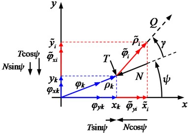
As a consequence, the following proposition is logical to consider an equivalent system, where a rotor is on supports as a combination of the same finite elements and where the additional support in the -th node is a non-rigid hinge (the free supporting by the compliant stator), which is unloaded here with a magnitude of the resultant of the same forces and . It is easy to see (Fig. 1) that the equivalent system is obtained “turned” relative to the original one by an angle equal to the friction angle .
A finite element formulation of the equivalent rotor – stator system with the increased transverse stiffness (with the greater coefficients of the stiffness matrix if compare to the original system), as well as with the oppositely directed contact forces:
Since the motion is assumed to be circular and stationary and reverse, and the solutions are:
where const, const, const, const, i.e. all amplitudes are real, positive and fixed.
Substitution of these expressions into the above equations gives:
If it is neglected by a gyroscopic influence and friction, then:
The right sides exception implies a fundamental equation of the rotor’s continuous slipping on the stator (it is important to note the motion is not necessarily a backward whirl due to square of ):
This equation is linear, therefore the mode superposition method can be applied i.e. the expansion for real displacements of rotor without and with support upon the stator on the eigenmodes of free from contact and supported rotor as well as the passing to the corresponding modal displacements:
where and are vector of dimensionless (relative) nodal displacements and their size (modal amplitude) for the -th eigenfrequency/mode of the contactless system, and – modal displacements for the -th eigenfrequency/mode of the contact system, is a number of the considered modes.
After substituting Eq. (4) into the matrix Eq. (3) and transforming for each of them to the reduced form i.e. after multiplying on the left by and the “resonant” or characteristic vibration mode and (which are the frequency-selective response of oscillatory system to a periodic external action, manifested by an increase in the amplitude of typical oscillations for a given system at the approach of external action frequency to one of the natural frequencies) will be:
where is the unit matrix, , .
From the orthogonality condition for the eigenmodes (which can be explained as an equality to zero for the inertia forces of the -th (-th) mode on displacements of the -th (-th) mode) it follows:
Therefore, the terms remain only at and :
Making substitutions and , it is possible to obtain an alternative record for the fundamental Eq. (3):
where is known vector of the real nodal displacements corresponding to the -th eigenmode of contactless system .
Due to the normalization on the inertial matrix (reduction to the unit matrix of masses):
where () is -th (-th) eigenfrequency of contactless (contact) system (here are frequencies of non-rotating system due to the definition).
As a result there are relationships:
Equating, it turns out that:
Multiplying from the right by , this equality can be inverted to a dependence between the modal amplitudes of the -th eigenmode of the supported rotor upon the stator and the -th eigenmode of the free from contact rotor:
where which can be called by coefficient of the eigenmodes superposition (the -th typical eigenmode of rotor before the stator touching is overlaid on the -th typical eigenmode of rotor after the stator touching without mutual influence on each other).
The amplitude of modal displacements for -th eigenmode of free rotor is determined from the contactless dynamics analysis of the rotor, for instance it is known, when the rotor is unbalanced and no the external friction:
where is rotary velocity, is -th angular critical speed of rotor, is vector of the unbalances (kg∙m).
Knowing the vector and amplitude of relative (modal) displacements when the rotor contacts the stator, one can determine the real amplitudes (amplitudes of the real displacements) in each “contact” eigenmode:
Summing the real amplitudes at all the considered eigenmodes, one can find the amplitudes of the real contact displacements of rotor:
A touching between rotor and stator appears due to the dynamic deflection of the contactless system. So, a vector is total real nodes displacements of the contact system. In an essence the total displacements determine the orbits radiuses of circular motion for the cross sections of rotor at the continual contact with stator. The total displacements can be compared relatively the radial clearance , where and are radiuses of rotor and stator surfaces at the contact point.
Since 0 then on the basis of Eq. (2) there should be:
Substitutions Eq. (4) and multiplying on the left by and and due to Eq. (5) yield:
As a result Eq. (6) and combining of the inequalities:
Ratio Eq. (7) describes the reaction of non-rotating non-damped flexible rotor – compliant stator system to the steady contact. It is possible if condition Eq. (8) of the existence or stability for continuous motion (slipping) of the rotor along the stator is fulfilled.
At the dependence of eigenfrequencies and eigenmodes , and , on the rotation speed (when the rotary effects are taken into account: gyroscopic action, internal, external and contact friction), the gyroscopic and friction contributions can be analyzed separately. This is permissible because of a negligible effect of the friction on the eigenfrequencies and eigenmodes.
3. Friction contribution in rotor slipping on stator
Returning to the equations of reverse uninterrupted motion for rotor along stator Eq. (1) without considering the gyroscopic moments and separating the real and imaginary parts, one can obtain:
Obviously and expectedly, the normal pressure force facilitates to the elastic forces of original rotor which is not provisionally supported by stator. The frictional forces counteract the contact friction force . However, the resulting contact force:
is opposite to the restoring forces of equivalent rotor which is supported by stator, i.e. the force in relation to the rotor is excitative.
If expand the contactless and contact real displacements on the corresponding rotor eigenmodes and pass to the modal displacements, i.e. if substitute Eq. (4) into Eq. (9), and then multiply the resulting equations on the left by and also by the typical eigenmodes and , one can obtained:
where , , , at the stator oscillations as a solid because corresponding matrix for viscous damping is varied, see the matrix Eq. (3) into the author’s paper [14].
Eigenvectors of the dynamic matrices are orthogonal, so the equalities Eqs. (5) and (6) are fulfilled as well as:
where or , , or is respectively the eigenvalue for rotating parts (rotor) and bearings or supports incl. for stator and contact at the -th (-th) eigenmode of contact (non-contact) system.
As a consequence the equations of backward slipping are simplified, in particular up to:
where , .
Elimination of and yields:
Multiplying on the right by leads to:
Unknown amplitude factors and will found from ratios:
Hence, due to the smallness of product as well as the squares and , firstly:
secondly:
i.e. the unknown whip velocity is determined by the fourth degree equation:
where , , , ( and at the fixed stator).
Obviously, the formula for calculating will be cumbersome, so it is reasonable to find a simplified solution with the help of tried approach [15].
In an absence of the viscous and hysteresis damping there will be:
i.e.: or .
With the friction there will be , where is some eigenfrequency of the contactless or contact undamped and non-rotating system, is some correction for due to the friction.
Submission as where is a small correction and substitution of this and approximate expressions:
in the fourth degree equation yield the introduced -correction:
As a rule, the hysteresis losses in rotor, bearing and stator materials vary slightly where is a hysteresis loss coefficient in materials of the system.
As a result:
Consequently:
In case of 0:
The existing ambiguity or is removable if we analyze analytical expressions:
With approach to , the modulus of whip velocity increase unrestrictedly in the first case, in the second case decrease without discontinuity. Physically, the friction increasing cannot produce the velocity increasing. Hence cannot be equal to .
Thus, the -additive to which determines , i.e. the angular whip velocity of backward whirl with slip for the flexible rotor on the compliant stator due to the contact friction:
or:
Since , then both with the small viscous damping and with the soft supports of rotor or stator the members with the factor will be close to zero:
The structural damping, in particular of the considered hysteresis and viscous type, is largely determined by a quality of parts and assembly of mechanism or machine. At the same time, an evaluation accuracy for the friction depends on experimental design, measuring equipment and so-called human factor. In combination, this gives an error commensurate with the result of approximation by Eqs. (10a) or (10b). Hence, contrariwise, Eq. (10) are in satisfactory agreement with reality (Fig. 2 and Table 1).
Fig. 2Experimental arrangement: 1 – horizontal steel shaft (diameter/length/mass of console = 8 mm/645 mm/0.255 kg), 2 – disk (0.270 kg), 3 – indicator (0.065 kg), 4 – stator imitator as the solid support with small radial clearance (r/δ= 2.65), 5 – safe support with large radial clearance, 6 – assembled ball bearings, 7 – frame plate, 8 – frame bracket, 9 – frame strut, 10 – electric motor, 11 – toothed belt drive, 12 – sensor for traverse displacements of shaft, 13 – sensor for rotary velocity of shaft
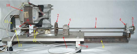
Table 1Dynamic characteristics of the experimental system
At the contact during run-up and shutdown | Test no. | Materials | Maximum rotary frequency, Hz | Ranges of rotary frequencies with stable backward rolling / Maximum frequencies and relative amplitudes of whipping in the appropriate speed ranges | |||||||
Of shaft in the contact place and of stator surface | Contact friction coefficient () | ||||||||||
, Hz | , Hz | ||||||||||
5 | 2.65 | Steel – Aluminum | 0.22 | 111 | 15÷43 | 51 | 1.4 | ||||
39÷105 | 118 | 1.76 | |||||||||
At the contactless run-up and shutdown and standing | Critical frequencies of rotational rotor on three ball bearings (without clearance in the bearing No. 4), Hz | Lower eigenfrequencies of nonrotational rotor, Hz | Loss coefficient in nonrotational rotor (η) | ||||||||
On two ball bearings (without the bearing No. 4) | On three ball bearings | On two ball bearings | On three ball bearings | ||||||||
50, 133 | 12, 58, 159 | 47, 126, 328 | 0.002 | 0.004 | |||||||
Fig. 3Diagram of the whirl and whip frequencies for the experimental rotor
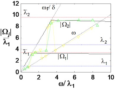
Fig. 3 illustrates the whirl and whip velocities of a materialized rotor in case of the backward rolling with slipping of its end on a stator. There are the velocities, which are predicted by the proposed theory (black continuous lines) and which are observed in experiments during a slow run-up and shutdown (color points are connected by green dot line for the run-up and yellow dot line for the shutdown).
4. Conclusions
As an alternative, for the existing models referring to rotor-stator system, for determining of the contact forces of normal pressure and dry or semi-dry friction, instead of the contact stiffness and contact damping coefficients, the vibratory displacements, velocities and accelerations of the equivalent system (i.e. the equation of its normal vibrations) are used. Thereby the unknown contact forces of the original system are excluded from consideration. Moreover, the original system is an -supported rotor loaded by the resulting of contact forces, but the equivalent system is a rotor on supports which is with increased stiffness (with larger coefficients of the stiffness matrix if to compare with the -supported rotor) as well as unloaded by the same amount .
Analysis of the dynamic characteristics of linearized isotropic system (of possible frequencies and amplitudes of the backward whirl for the rotor rolling with slipping upon the stator) is fulfilled in a general form based on the beam model, taking into account the gyroscopic effect. Also, the matrix methods, the eigenmodes expansion for real rotor displacements as well as the method of a small parameter i.e. a small correction to eigenfrequencies due to the structural and contact friction in the system are used.
The obtained main theoretical results are in agreement with the known experimental ones. First, the stability conditions of the rolling with slipping are:
where is absolute value for the whip velocity of the backward rotor whirl, is rotor velocity, is rotor radius, is clearance in the contact place, is -th eigenfrequency of free from contact rotor, is -th eigenfrequency of supported rotor by the stator.
Secondly, the whip velocityof the rotor slipping upon the stator is close to , scilicet:
where is the hysteresis loss coefficient in the materials or is equal to the logarithmic decrement in the system, is coefficient of the slip friction.
Thirdly, the friction preventing to the forward slipping i.e. making it an unstable motion of the contactless unloaded (other forces of non-contact origin) isotropic rotor – stator system, leads to setting of the backward rolling with slipping. At the same time, the contact friction weakly affects the whip amplitude which is conjugate with the backward slipping, but it sets the whip frequency. Due to the friction influence, the whip frequency of backward slipping for rotor upon stator is always slightly below one or another eigenfrequency of the contact system. And the contact friction does not affect the whip frequency without structural damping.
References
-
Billett R. A. Shaft wheel induced by dry friction. The Engineer, Vol. 220, Issue 5727, 1965, p. 713-714.
-
Begg I. C. Friction induced rotor whirl – a study in stability. ASME Journal of Engineering for Industry, Vol. 96, Issue 2, 1974, p. 450-454.
-
Cveticanin L. Stability of a clamped-free rotor with variable mass for the case of radial rubbing. Journal of Sound and Vibration, Vol. 129, Issue 3, 1989, p. 489-499.
-
Shen X., Jia J., Zhao M. Effect of parameters on the rubbing condition of an unbalanced rotor system with initial permanent deflection. Archive of Applied Mechanics, Vol. 77, 2007, p. 883-892.
-
Chu F., Lu W. Determination of the rubbing location in a multi-disk rotor system by means of dynamic stiffness identification. Journal of Sound and Vibration, Vol. 248, Issue 2, 2001, p. 235-246.
-
Yu J. J., Goldman P., Bently D. E., Muszynska A. Rotor/seal experimental and analytical study on full annular rub. Journal of Engineering for Gas Turbines and Power, Vol. 124, Issue 2, 2002, p. 340-350.
-
Grapis O., Tamuzs, Ohlson N. G., Andersons J. Overcritical high-speed rotor systems, full annular rub and accident. Journal of Sound and Vibration, Vol. 290, 2006, p. 910-927.
-
Shaw A. D., Champneys A. R., Friswell M. I. Asynchronous partial contact motion due to internal resonance in multiple degree-of-freedom rotordynamics. Proceedings of the Royal Society A: Mathematical, Physical and Engineering Sciences, Vol. 472, Issue 2192, 2016, https://doi.org/10.1098/rspa.2016.0303.
-
Childs D. W., Bhattacharya A. Prediction of dry-friction whirl and whip between a rotor and a stator. Journal of Vibration and Acoustics, Vol. 129, 2007, p. 355-362.
-
Sawicki J. T., Montilla Bravo A., Gosiewski Z. Thermomechanical behavior of rotor with rubbing. International Journal of Rotating Machinery, Vol. 9, Issue 1, 2003, p. 41-47.
-
Zhang G. F., Xu W. N., Xu B., Zhang W. Analytical study of nonlinear synchronous full annular rub motion of flexible rotor-stator system and its dynamic stability. Nonlinear Dynamics, Vol. 57, 2009, p. 579-592.
-
Lahriri S., Weber H. I., Santos I. F., Hartmann H. Rotor-stator contact dynamics using a non-ideal drive - Theoretical and experimental aspects. Journal of Sound and Vibration, Vol. 331, 2012, p. 4518-4536.
-
Nikiforov A. N., Shokhin A. E. Elastoplastic viscous model of rotor–stator impact interaction without separation. Mechanics of Solids, Vol. 51, 1, p. 54-64.
-
Nikiforov A. Multiple-degree-of-freedom rotor model with total unbalance and possible contact on stator. IOP Conference Series: Materials Science and Engineering, Vol. 489, Issue 1, 2019, p. 012041.
-
Brysin A., Nikiforov A. General approach determinating eigenfrequencies of gyroscopic system with friction. Mechanics of Solids, Vol. 3, 2019, p. 100-107, (in Russian).
About this article

The research work was supported by the Russian Foundation for Basic Research, project No. 18-08-00171.
