Abstract
Dynamic features of a rotor that rolls without or with whipping and slipping of own inner surface on a rigid stator are discussed. Change in the whirling direction associated with the rolling of the rotor from backward to forward was confirmed experimentally, i.e. in the case of an internal type for the stator-limiter in the direction of rotor rotation. Identification of dynamic behavior is made on the basis of eigenfrequencies and eigenmodes, motion orbits of an eccentric point (on the rotor), Campbell diagrams and AFC. The calculation of such characteristics has done using an original mathematical approach developed by the author earlier in order to describe the backward motion of common rotor on an external stator. A good agreement is obtained between the theoretical frequencies and amplitudes of vibration and the experimental ones. Therefore, the author’s technique is also suitable for the revealed forward rotor motion around the internal stator.
Highlights
- Rolling of outer rotor on inner stator = forward whirling
- Forward slipping of outer rotor on inner stator = forward whirling with whipping of outer rotor
- Angular speed and whip amplitude of forward slipping are calculated values now as well as for backward slipping of normal rotor inside stator
1. Introduction
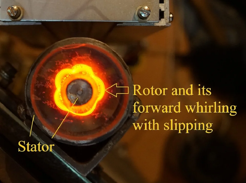
In some rotating machinery, such as centrifuges, washing machines, and superflywheels (gyroscopic energy storage), the relatively rigid rotor is supported by very compliant bearings. The supercritical work and using complexity of the viscous dampers enforce to introduce into a design amplitude limiters of rotor oscillations, i.e. its whirling or/and whipping. The limiter works only in emergency situations, when the whirl/whip amplitude exceeds the specified clearance between rotor and limiter, i.e. the stator. The slipping of rotor on the stator in the specified position prevents the friction between rotor and stator in other places. Stiffness of the limiter is usually much greater than that of bearings. Sometimes with that, it is an internal cylinder inside the hollow end of rotor (Fig. 1).
Despite of the design simplicity there are no results of mathematical and natural modeling for the outer rotor – inner stator system and its unseparated dynamics. And this is despite the rather extensive and fresh scientific and technical literature on a similar problem for a typical rotor system with outside stator [1-10].
Fig. 1Scheme of rigid rotor on elastic bearings with stator inside
2. Outer rotor – inner stator model
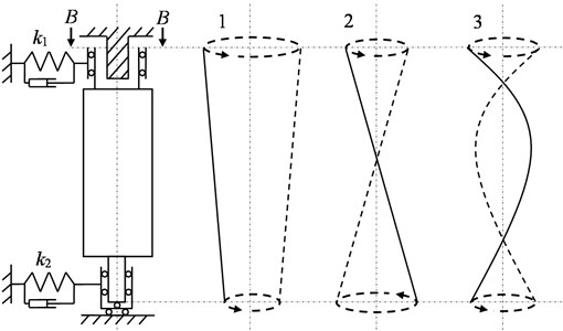
The rotor is assumed to be rigid and axisymmetric, and also supported on unequal linear elastic bearings (Fig. 1). Also shown are two characteristic modes of natural oscillations of the rotor under such conditions: 1 – cylindrical and 2 – conical. An uncharacteristic third mode is high-frequency rotation at speeds when elastic deformation of the rotor itself occurs, i.e. in the vicinity of the first natural or bending frequency of the rotor on rigid bearings.
In some cross sections, the transverse whirl displacements of a rigid rotor on elastic bearings differ little from the whipping of a flexible rotor on rigid bearings. This fact allows transferring the results from one rotary model to another. Fig. 2 shows a comparison of a rotor previously researched under various conditions of its rolling without and with whipping and slipping along an external stator-limiter [10], as well as a rotor recently experimentally examined with an internal-type stator-limiter.
Modification to the previously materialized setup was minimal. It is reduced to a nozzle of cap on the end of cantilevered steel shaft 645 mm long and 8 mm in diameter. The cap is a hollow aluminum cylinder with an inner working diameter of 12 mm, an LED, a 3 V coin cell battery and a total weight of ≈ 20 g. As well as it is replaced the end support with a clearance (which had a sleeve with an inner diameter more than 8 mm) on a support made of steel and plexiglass of suitable size, in which a rod with a diameter of 10 mm made fluoroplast-4 or steel and was rigidly fixed (inside its sleeve made of plexiglass).
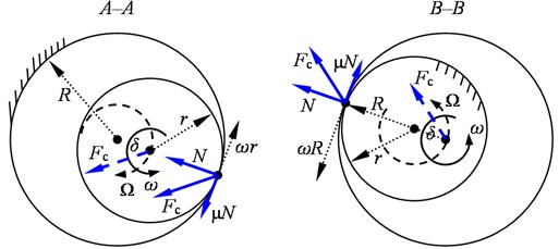
Look at the schemes of contact loading and non-separated motion of the discussed systems (Fig. 3), we can conclude that the B–B type of interaction is preferable to the A–A type. In a B–B type system, the resulting from the normal contact force and the dry friction force causes the rotor whirling in the direction of rotation, which helps to reduce internal stresses (in the rotor). However, the above obvious was not confirmed by experiments due to the positive supersynchronous velocity of whirl/whip ().
Fig. 2Scheme of experimental flexible rotor on rigid bearings with stator outside [10] and inside
![Scheme of experimental flexible rotor on rigid bearings with stator outside [10] and inside](https://static-01.extrica.com/articles/23104/23104-img2.jpg)
Fig. 3Contact forces and whirling directions of rotor rolling with its outer and inner surface around stator
3. Summary on dynamics
In general, transformation of the previously tested flexible rotor into a hollow, point-like light on it, transparency of the constructed internal support and photography with long exposure made it possible to observe the real trajectories of eccentric Fig. 4, the effect of clearance geometry, directions, ranges Table 1, velocities Fig. 5(a) and amplitude Fig. 5(b) of the rotor whirl/whip at rolling around the stator with its inner surface. Author’s photos (Fig. 4) and all other related results are received recently in Vibromechanics Laboratory of the Mechanical Engineering Research Institute.
In particular, the orbits have always been with loops facing inwards (towards the rotor axis). The directions of trajectories were always forward, i.e. in the direction of rotation of rotor. The ratio , where is the radial clearance between contact surfaces, is the radius of outer (r – inner) contact surface, sets a maximum number of loops, i.e. in case of rolling without whipping and slipping. The fraction is equal to a maximum number of forward whirling (i.e. revolutions of the axis) of the rotor in one revolution of its own rotation, and multiplying by the rotation speed gives the angular velocity of clean rolling.
In an usual system with rotor inside and stator outside, during the rolling and whip phenomenon: the trajectory loops are turned to a periphery (from the rotor axis), the ratios and set the largest number of loops and backward whirling respectively for each rotation of the rotor, the product is equal to velocity of the rolling without whipping and slipping.
Table 1The effect of clearance geometry, directions, ranges
Vertical, steel, round ( 4 mm) shaft with hollow cylinder (at the end) | ||||||||
Contact characteristics of the system in series of “rolling” tests | No. startup-shutdown | Ratio | Materials | Highest frequency of rotation , Hz | Ranges of rotation frequencies in case of stable rolling with slipping, highest frequencies and amplitudes of forward whirl/whip in corresponding speed ranges | |||
Shaft at the point of contact - stator rod | Friction coefficient of slipping () | |||||||
, Hz | , Hz | , mm | ||||||
1 | 6 | Aluminum – fluoroplast-4 | 0.11 | 96 | 5-49 | 51 | 0.31 | |
66-96 | 54 | 0.3 | ||||||
2 | 6 | Aluminum – steel | 0.2 | 88 | 5-48 | 62 | 0.22 | |
71-88 | 66 | 0.22 | ||||||
3 | 6 | Aluminum – steel | 0.2 | 76 | 6-48 | 68 | 0.21 | |
48-52 | 186 | 0.27 | ||||||
61-76 | 341 | 0.29 | ||||||
50-22 | 98I | 0.1 | ||||||
4 | 6 | Aluminum – steel | 0.2 | 76 | 5-60 | 69 | 0.29 | |
60-76 | 180 | 0.39 | ||||||
5 | 5.5 | Aluminum – steel | 0.2 | 83 | 4-50 | 68 | 0.23 | |
50-52 | 278 | 0.26 | ||||||
6 | 5 | Aluminum – fluoroplast-4 | 0.14 | 92 | 5-46 | 51 | 0.31 | |
75-92 | 66 | 0.3 | ||||||
54-50 | 159 | 0.35 | ||||||
50-44 | 57 | 0.34 | ||||||
44-5 | 68 | 0.3 | ||||||
7 | 4.33÷3 | Aluminum – steel | 0.2 | 79 | 5-59 | 69 | 0.3 | |
30-71 | 93I | 0.17 | ||||||
Dynamic characteristics (averaged) of the system | Lowest natural frequencies of non-rotating shaft after series of tests (Hz) | Loss factor inside the rotating shaft after series of tests () | ||||||
As unsupported on stator | As supported on stator | |||||||
10, 74, 212, 420 | 60, 191, 390 | 0.003 | ||||||
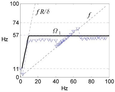
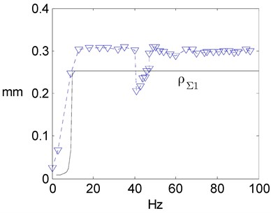
The appearance of supersynchronous velocities or frequencies is taken as the main attribute of rolling with whipping and slipping (Table 1). For example in experiment No. 1, supersynchronous oscillations was recorded in a shutdown phase at the rotation frequencies from about 40 to 10 Hz (Fig. 5). An additional attribute of rolling with whipping and slipping was the occurrence of specific trajectories for the rotor eccentric point with inward-looking loops (Fig. 4). Subsynchronous frequencies are also indicated in table 1 as accompanying the rolling with whipping and slipping, because their values differ little from those detected during supersynchronous motion, and they are characterized by orbits with one or more loops facing the rotor axis for any of its eccentrics and simultaneously circular whirling of the rotor axis itself. For example, subsynchronous rolling with whipping and slipping was observed during shutdown No. 1 and rotation frequencies from about 100 to 65 Hz (Fig. 5), while when synchronous motion occurred in the range of ≈ 65-40 Hz, the all rotor orbits (of axis and eccentrics) were circular.
Theoretical parameters for the -th form of rolling with whipping and slipping in the Fig. 5 are determined by the author’s method [10]. The discussed systems (Fig. 1, 2) are simulated mathematically and enough lightly in the finite element formulation:
where are complex displacements of rotor sections with concentrated mass and transverse inertia moment, is vector of contact forces dominating over all other system forces, i.e. for instance as general case where 1 corresponds lateral displacement of contact section or th section with the -clearance between rotor and stator, is whirl angle of contact forces or rotor axis in the contact section, is positive value at the forward whirl and negative value at the backward whirl. Let it is the original system, consisting of a rotor on two or bearings.
Fig. 4Orbit evolution of the eccentric during continuous forward whirling with whipping and slipping of the “outer” rotor on the “inner” stator with an increase of rotary velocity as rev/min (Startup No. 5, September 2022)
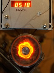
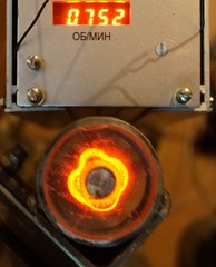
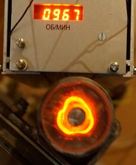
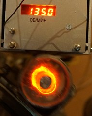
Fig. 5Measured at startup No. 1 (▽) and theoretical frequencies and amplitudes of the whirling for the steel experimental rotor rolling without and with whipping and slipping around the “internal” stator, i.e. a) Campbell diagram of the rotor and b) its amplitude characteristic by rotary frequency
On the other hand, an equivalent system with rotor on the supports and zero clearance in the contact section can be considered, governed by the matrix equation, which at the same time is locally destabilized by the opposite forces :
wherein the matrix differs from only by an adding of relevant contact stiffness between th rotor section and stator.
Obviously, solutions of the written equations can be assumed in the harmonic forms:
where is lag for the whirl/whip displacements of equivalent system relative to the original one by an amount equal to the friction angle, i.e. satisfying the identity .
So, it can be derived a fundamental equation of rolling which includes square of velocity and doesn’t depend from sign of :
or
As a result, the used method yields that frequencies and amplitudes of vibration in case of the rolling with whipping and slipping are defined by dominating natural frequencies and modes of the rotor:
4. Conclusions
For the first time, the real motion of rotor is demonstrated, which accompanies the rolling phenomenon of an outer rotor on an inner stator.
The universal calculation method is proposed for all rotary contact systems that predicts a frequency and amplitudes of the whirling and whipping associated with rolling and slipping of rotor on stator.
References
-
N. Salvat, A. Batailly, and M. Legrand, “Two-dimensional modeling of unilateral contact-induced shaft precessional motions in bladed-disk/casing systems,” International Journal of Non-Linear Mechanics, Vol. 78, pp. 90–104, Jan. 2016, https://doi.org/10.1016/j.ijnonlinmec.2015.10.001
-
N. Vlajic, A. R. Champneys, and B. Balachandran, “Nonlinear dynamics of a Jeffcott rotor with torsional deformations and rotor-stator contact,” International Journal of Non-Linear Mechanics, Vol. 92, pp. 102–110, Jun. 2017, https://doi.org/10.1016/j.ijnonlinmec.2017.02.002
-
T. Popp, H. Stibbe, D. Heinisch, H. Reckmann, and P. Spanos, “Backward whirl testing and modeling with realistic borehole contacts for enhanced drilling tool reliability,” in IADC/SPE Drilling Conference and Exhibition, Mar. 2018, https://doi.org/10.2118/189600-ms
-
J. C. Wilkes, “Application of Dry-friction whip and whirl solution methods to systems with support asymmetry,” in ASME Turbo Expo 2018: Turbomachinery Technical Conference and Exposition, Jun. 2018, https://doi.org/10.1115/gt2018-76991
-
U. Ehehalt, O. Alber, R. Markert, and G. Wegener, “Experimental observations on rotor-to-stator contact,” Journal of Sound and Vibration, Vol. 446, pp. 453–467, Apr. 2019, https://doi.org/10.1016/j.jsv.2019.01.008
-
E. G. Ovy, “Suppression of rubbing in rotating machines by lemon-type bearing,” Journal of Vibration and Acoustics, Vol. 141, No. 5, Oct. 2019, https://doi.org/10.1115/1.4043817
-
M. Behzad and M. Alvandi, “Friction-induced backward rub of rotors in non-annular clearances: Experimental observations and numerical analysis,” Tribology International, Vol. 152, p. 106430, Dec. 2020, https://doi.org/10.1016/j.triboint.2020.106430
-
Y. Briend et al., “Dry-whip phenomenon in on-board rotordynamics: Modeling and experimentation,” Journal of Sound and Vibration, Vol. 513, p. 116398, Nov. 2021, https://doi.org/10.1016/j.jsv.2021.116398
-
A. K. Srivastava, M. Tiwari, and A. Singh, “Identification of rotor-stator rub and dependence of dry whip boundary on rotor parameters,” Mechanical Systems and Signal Processing, Vol. 159, p. 107845, Oct. 2021, https://doi.org/10.1016/j.ymssp.2021.107845
-
A. N. Nikiforov, Applied Semi-Empirical Theory for Non-Separated Motion of Rotor on Stator. (in Russian), Saint-Petersburg: SUPER Publishing House, 2021, https://elibrary.ru/ktaeka
About this article

The authors have not disclosed any funding.
The datasets generated during and/or analyzed during the current study are available from the corresponding author on reasonable request.
The authors declare that they have no conflict of interest.
