Abstract
In single and multiphase flows, an orifice is a vital flow-measuring and flow-controlling device that operates on Bernoulli’s theorem on the determination of the pressure drop (). Laboratory, petroleum, energy, nuclear, mining, chemical, processing, and food industries all depend on flow monitoring and flow regulations. A sector or segmental orifice meter is a much simpler device used for drainage and sediment-laden type non-homogeneous flow. Sector orifice meter analysis is the rate of flow, pressure and velocity profile concerning input parameters to find out the and coefficient of discharge () of an orifice meter. The present study varies with different sector angles (), Reynolds number (Re) and space ratio () of the sector orifice for the flow analysis with the use of CFD (Ansys. Inc) based study. The numerical simulation range considered for (30°-180°), Re (10000-100000), and / (0.1-0.9). To compute the flow rate, and by using air as a working fluid to present a flow problem through high viscous flow. The simulation also presents the pressure and velocity profiles along the flow on the variant of Re, and /. Based on the numerical data a correlation developed which will help the measurement through sector orifice for wide range of future application. With the comparison of the existing literature, this will give a good contribution to sector orifice for accurate flow measurement for high viscous flow.
Highlights
- Calculate Δp and coefficient od discharge for sector orifice with air using CFD.
- Sector angle, Space ratio and Re as input parameters to determine Δp and Cd.
- The predicted parameter comp red with the existing literature database.
1. Introduction
To calculate the mass flow rate along flow through a pipe, several flow measuring equipments such as an orifice meter, nozzle, and venturi meters are utilized. An orifice meter is an essential instrument for measuring flow using the principle of sensing pressure drop [1-3] because of its simple design, production, dependability, and cost-effectiveness. In the oil and gas business, wellhead chokes are used to manage well output, decrease pressure changes downstream of the choke, and prevent the formation of damage due to excessive drawdown by putting the necessary backpressure on the reservoir [4]. A crescent orifice is used for drainage, and a sluice gate discharges water from dams, bridges, and gas wells to recover petroleum products and gas. The flow rate of light slurries, gases with non-abrasive impurities, and fluids with a high concentration of solids is measured using crescent orifice plates. The primary limitation of these sorts of crescent orifices is that they are not as precise as concentric orifices. The eccentric orifice forms a barrier for foreign particles and provides more complete drainage than the orifice design. The sector orifices available in the literature are not provided accurate measurement for the flow because of turbulent, wake, reverse flow with high viscosity. The present study will be provided a error minimizing correlation for the or mass flow measurement for the sector orifice with air as a trail fluid.
Sediment flow is an extremely viscous, gravity-dominated flow that is useful for a variety of flow problems. Because the concentric orifice has a significant degree of uncertainty in terms of sediment movement, a sector orifice is considered an option. The pressure variation and discharge coefficient were evaluated using a pipe diameter of 40 mm, an area ratio () of 0.2-0.8, of 0.2-0.9, of 72°-288°, and Re, based on the experimental data, a correlation was also developed [5]. An experimental result, an elliptical orifice is compared with a circular orifice to estimate the discharge coefficient. The pipe diameter used is 38.1 mm, with a diameter ratio range of 0.2-0.8 for two distinct elliptical orifice orientations [6]. A comparison study uses laser Doppler measurements for a segmental orifice of 33 %, 7 % of , and 90° bend as an alternative to ultrasonic and magnetic flow meters to depict varied flow circumstances [7]. A hybrid simulation for a segmental orifice plate utilized as an ultrasonic meter application using the - RANS (Reynolds-Averaged Navier-Stokes) model and comparing it to LDA (Laser Doppler Anemometer) results [8]. To rectify the error of Chislom data for different σ for a V-cone flow meter was employed for the gas-liquid flow of a stratified flow [9-10].
To eliminate ambiguity along the flow, the natural gas industries use a slotted orifice as a turbine flow meter to monitor the flow rate of steam [11]. To determine the flow coefficient, a numerical investigation of the slotted orifice on the modification of geometrical factors such as aspect ratios and σ with the k-model was undertaken [12]. A wet gas meter was utilized with a slotted orifice to calculate the pressure, velocity, and density contours over the flow domain. Better pressure recovery, consistent and stable velocities on both upstream and downstream flow regimes and lower are provided by the slotted orifice [13]. Similar studies were done [12, 14-15] to figure out the flow coefficient for a slotted orifice. The and analysis for the discharge coefficient are taken into consideration for a two-stage orifice. For the examination of a 3 mm diameter orifice, which provides better control than a single orifice, the mineral oil is classified as a fluid with a Reynolds number in the range of 900 to 1700 [16]. Numerical analyses of crescent orifice considered for optimizing the geometrical parameter based on flow analysis are reported [17]. To determine the impact of unstructured geometry on the output for high-volume fraction problems, a crescent orifice is employed as a flow meter for gas-stratified flow [18]. For the two-phase theoretical analysis of a gas-liquid mixture of the pipe and orifice to calculate the single flow coefficient, sharp-edged orifices were taken into consideration. The ratio of phase velocities, variation in across the flow, and gas-liquid weight ratio with shear stress impact are the factors taken into account for calculating the flow coefficient [19]. In order to determine the and on R-113 fluid flow based on experimental and theoretical investigations. The study of orifice was also taken into consideration for two-phase separated flow measurements on the change of 4 different vapor-liquid density ratios [20]. A subsonic and critical-flow regions analysis was used to experimentally determine the flow behavior of compressible fluid (air) through various types of convergent nozzles with diameters ranging from 0.9 to 1.9 mm, including knife-edge orifices, straight-bore orifices, rounded-entry nozzles, and elliptical-entry nozzles [21]. To study the influence of the experimentally, a multi-orifice valve was utilized to measure frictional , two-phase frictional multipliers, and void fraction. A correlation for two-phase frictional multipliers for a multi-orifice valve was created based on the experimental investigation [22]. For a numerical investigation, a circular orifice with a thin and thick orifice is taken into consideration. (0.4 to 0.8), (0.125 to 0.5), and Re (5000-50000) with various fluids are the operational conditions. Static pressure, velocity profile, and contraction are all determined by the investigations [23]. A thin and thick orifice is considered for single-phase non-dimensional (Orifice Number) correlation-based studies carried out for an orifice [24, 25].
To study pressure loss throughout the flow, an orifice was considered as a jet impingement device using FVM-based software Fluent [26]. Water and air [27] as the working fluids to calculate the value of using the Open FOAM solver, a CFD-based technique. The present numerical studies will be carried out for a sector orifice to determine the and , for a highly viscous application with air as a working fluid. To conduct the numerical experiments, different input parameters including Reynolds number (Re), sector angle () and space ratio (), of the sector orifice. Based on the predicted numerical database a correlation will develop for and to produce a better flow phenomenon with the comparison of existing correlated databases.
2. Numerical analysis
2.1. Geometrical model
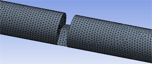
Sector orifice used for sediment laden, high viscous flows like drainage and sewage applications. The sector orifice plate is another type of orifice as per the geometric configuration in the form of a sector of a circle as shown in Fig. 1. The flow is varied with the variation of as mentioned in the different profile in Fig. 1. The opening of the sector orifice is in the bottom of the plate to provide free passage for the flowing of high viscous sediment to avoid blockage in the system. The mesh model of the sector orifice also represents in the Fig. 2 for geometrical profile of 120° concern.
Fig. 1Geometric models of the sector orifice on the variation of θ
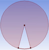
a) 30°
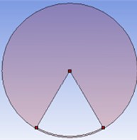
b) 60°
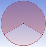
c) 120°
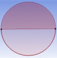
d) 180°
Fig. 2Mesh models of the sector orifice for θ= 120°
2.2. Assumptions
The present numerical studies have taken into the following assumption for the present flow analysis.
– Air is considered Newtonian, viscous and incompressible.
– Time factor not taken into account for the studies.
– The edge effect of the orifice plate is negligible.
– The properties of the fluids remain constant throughout the flow domain.
– The axial velocity components are considered for the flow calculation.
– No-body force was considered for the analysis.
2.3. Governing equation
Based on the flow physics governing equations chosen as mentioned in the Eqs. (1-6) as per the flow physics of the numerical problem.
Continuity:
Axial momentum:
Radial momentum:
Azimuthal momentum:
Turbulence model kinetic energy:
Dissipation rate of Turbulent Kinetic energy:
and is eddy viscosity.
2.4. Grid independent study
A grid-independent study was carried out for sector orifice flow problems. The orifice flow depends on the calculation of . The is measured with the tapping placed before 0.5D of the orifice and after the 2D distance of the orifice. The grid-independent study is important in the above-mentioned zone, so the has been calculated for different intensities of mesh to carry out the study. The element size continuously reduces for increasing the sizes of meshes. The present numerical study considers 48 nos. of sector models. The study parameters taken for the grid study are 120°, Re = 60000, and 0.3 which are present in the grid-independent study. The different mesh sizes considered for the grid-independent study are 43018, 73515, 109858, 173919 and 322243. The mesh sizes selected for the numerical study based on grids are 173919 as mentioned in Table 1.
Table 1Grid independent study
Sl no. | 1 | 2 | 3 | 4 | 5 |
Mesh size | 43018 | 73515 | 109858 | 173919 | 322243 |
(Pa) | 9928 | 10346 | 10624 | 10727 | 10728 |
2.5. Numerical methodology
Ansys (fluent) [29] is a CFD-based, FVM (Finite Volume Method) technique used for carrying out numerical studies for the sector orifice. A 3D model with cylindrical coordinate sector orifice pipe flow is considered for the mesh creation with the use of a mesh tool. A high-quality mesh with a better aspect ratio, the unstructured mesh is generated for the sector flow domain. The flow domain discretizes least square cell-based, spatial discretization method is implemented with finite-volume method tool. The accurate flow analysis took care of adding more elementary volumes near the sector orifice region and wall treatment model to minimize the grid effects on the predicted results. The cylindrical effect was reduced with the implementation of O-grid mesh correction for uniform volume mesh. The grid-independent investigation with the variation of no of grid shape and size was also carried out for perfect results. Air as single phase flow is considered for the flow fluid. The pipe diameter is 102.6 mm (4 inches). The boundary condition is considered for inlet as velocity inlet, outlet as pressure outlet at the outlet, and no-slip for the numerical analysis. The numerical result was strengthened by the -model turbulent with wall behavior. The governing equations of continuity, momentums, turbulent kinetic energy, and turbulent energy dissipation rate (- model) are used to solve the single-phase flow problem. SIMPLE (Semi-implicit method for pressure-linked equation) algorithm is used for pressure-velocity coupling. The standard scheme for pressure and the second-order upwind scheme are considered for momentums, turbulent kinetic energy, and turbulent dissipation rate for solving the governing equations. Under Relaxation Factor (URF) chosen for the control of numerical solution to get converged results for pressure, density, body forces, momentum, turbulent viscosity, turbulent kinetic energy, and turbulent dissipation rate. The residual plots are used to plot the converge proceeding of the numerical solution. The converge limit is 10-3 for continuity, 10-5 for momentum and turbulent equations are taken into account. Before calculating the solution, standard initializations are performed.
3. Result analysis
The numerical research took into account a sector orifice plate flowing in a pipe diameter of 4 inches (101.6 mm), and 2 inches (50.8 mm). The input parameters for the present studies are / = 0.1 to 0.9, 30° to 180° and Re = 10000 to 100000. The numerical study validates with the existing literature of sector orifice conducted by (Yadav, 1995). The data considered for the validate study are 180°, Re = 20000 to 200000, and water as working fluid. The validation results differ with a deviation of 8 % which shows good agreement based on the working procedure consideration. Fig. 3 shows different shape of orifices such as crescent, sector, segmental and circular orifice for the same σ value to represent comparison studies of flow profile of orifice.
Fig. 3Different shapes of orifices
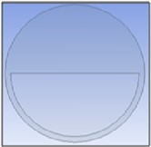
a) Crescent
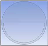
b) Sector

c) Segmental

d) Circular
The validation study further extends to a comparison study for different shape of orifice which present in Fig 4. Fig. 4 shows a comparison study of the crescent, sector and circular orifice for the Fig. 4(a) and Fig. 4(b) . The study shows that sector orifice produce a performance better than crescent, segmental and circular orifice for determination of for same . The determination of also shows similar types of trends but the value better for circular orifice than other orifices for same .
Fig. 4Comparison of different orifice
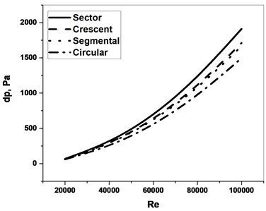
a)
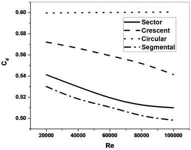
b)
Fig. 5 shows the static pressure and velocity magnitude profile of the sector orifice. The static pressure increases after the orifice because of sudden contraction in the area at the orifice, and increases after flow past the orifice, then decreases as the flow progresses towards the exit of the pipe as represented in Fig. 5(a). The static pressure magnitude increases with the increases of Re and produces maximum magnitude in Re = 100000. The velocity magnitude has the reverse phenomenon of the static pressure profile which has a sudden drop after the flow past the orifice presented in Fig. 5(b). Fig. 6 depicts the graphical representation of the static for different of the sector orifice. The profile produced in the graphical view as 30°, 60°, 120°, and 180° for Re = 60000 in Fig. 6.
Fig. 5Flow profile of sector orifice along the flow length on the variation of Re
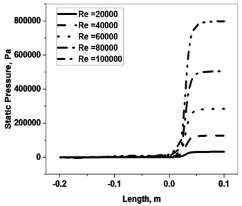
a) Static pressure
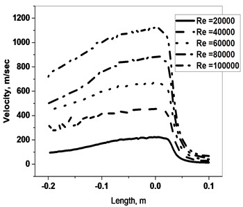
b) Velocity magnitude
The of the orifice is a function of Re with direct proportionality. The for different on the variation of Re is represented in Fig. 7. The profile suggests that at lower , is more because of narrow flow passage and the decreases as value increases. The flow phenomenon occurs due to is directly proportional to , where a is the area of the orifice and area of the pipe. Fig. 8 shows the for different Re on the comparison of thin and thick orifices. The thin and thick orifice is defined based on the thickness of the orifice. If the / is less than 0.5 then thin orifice, else thick orifice (Chislom, 1967). The thick orifice produces more than the thin orifice for a particular Re, because of more thickness but provides a stable profile for . Fig. 8 shows three different thickness ratios of sector orifice (0.2 to 0.6) on the categories of the thin and thick orifice. Due to the increase in the thickness ratio, 1 to 2 % decreases in the .
Fig. 6Streamline representation of static pressure profile of different sector orifice
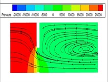
a) Profile of 30 °
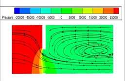
b) Profile of 60 °
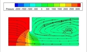
c) Profile of 120 °
Fig. 7∆p for different θ on the variation Re
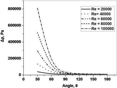
Fig. 8∆p for different Re for thin and thick orifice
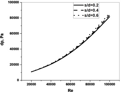
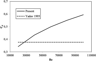
Fig. 9 shows on the variation for different Re. The of the orifice shows more magnitude for lower Re for a particular or . Fig. 10 represents the comparison of on the variation of with (Yadav, 1995) for different . (Yadav,1995) correlation is a function of Re only but the present study is the function of Re and the which is the reason for the difference in the trend line. Similar results were found when the comparison study was produced for Cdfor function only as represented in Fig. 11. The studies concluded that the and not only depend on Re, and but also depend on the area of other parameters a new correlation proposed for the study of sector orifice.
Fig. 9Cd for different θ on the variation of Re
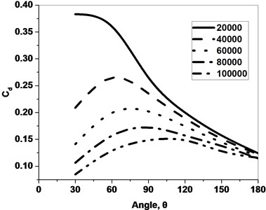
Fig. 10Comparison Cd on the variation of σ
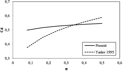
Fig. 11Comparison Cd on the variation of Re
4. Correlations
Two correlations are proposed for the sector orifice to determine the and as a function of Re and as represented in the Eq. (7) and Eq. (8). The correlation developed based on a MATLAB code and the multi-regression analysis tool based on least squares method. GARCH (Generalized Autoregressive Conditional Heteroskedasticity), is suitable to the above methods to develop the correlations. The correlation coefficient (, , ) for the Eq. (7) and (, , ) for the Eq. (8) is determined:
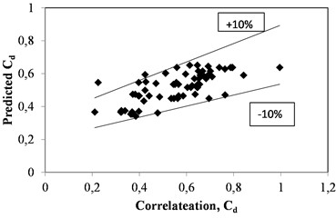
The correlation yields accurate results with a 10 % maximum margin of error to the predicted numerical data. The correlation graphs are present in Fig. 12 and Fig. 13 for and . respectively.
The correlations are represented with the correlation coefficient in the Eq. (9) and Eq. (10):
Fig. 12Correlation graph for Δp
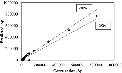
Fig. 13Correlation graph for Cd
5. Conclusions
A sector orifice is considered for the numerical analysis on the variation of sector angle (), Reynolds number (Re) and space ratio (/) to determine and . The static pressure and velocity magnitude along the flow through the sector orifice have been determined. The profile shows the static pressure profile increase and velocity magnitude decrease after passing through the sector orifice. The pressure drop () increases with the increase of Re for different sector angles (). The and values were compared with existing literature databases on the variation of Re, and /. The thickness of the orifice plays a less important on the determination of and , but for accurate measurement of flow, the effect of thickness should not neglected. Based on the predicted result database correlations also developed for and with good agreement which will predict the mass and in a effective way for a sector orifice. The present numerical studies provide valuable information for designing the sector orifice for the betterment of high viscous flow.
References
-
“Fundamentals of orifice meter measurement,” https://www.emerson.com/documents/automation/white-paper-fundamentals-of-orifice-meter-measurement-daniel-en-us-188730.pdf
-
S. K. Panda, B. K. Choudhury, and K. C. Rath, “A literature review on orifice as a flow measuring device,” ECS Transactions, Vol. 107, No. 1, pp. 815–826, Apr. 2022, https://doi.org/10.1149/10701.0815ecst
-
M. Reader-Harris, Experimental Fluid Mechanics. Cham: Springer International Publishing, 2015, https://doi.org/10.1007/978-3-319-16880-7
-
G. H. Abdul-Majeed and R. A.-A. Maha, “Correlations developed to predict two-phase flow through wellhead chokes,” Journal of Canadian Petroleum Technology, Vol. 30, No. 6, Nov. 1991, https://doi.org/10.2118/91-06-05
-
H. S. Yadav, M. Athar, and D. R. Kaushal, “Flow characteristics of sector orifice plates,” ISH Journal of Hydraulic Engineering, Vol. 1, No. 2, pp. 84–94, Jan. 1995, https://doi.org/10.1080/09715010.1995.10514576
-
M. Athar, M. A. Ansari, and M. A. Khan, “Flow characteristics of elliptical orifice plates,” ISH Journal of Hydraulic Engineering, Vol. 9, No. 2, pp. 22–35, Jan. 2003, https://doi.org/10.1080/09715010.2003.10514731
-
M. Straka, C. Koglin, and T. Eichler, “Segmental orifice plates and the emulation of the 90°-bend,” tm – Technisches Messen, Vol. 87, No. 1, pp. 18–31, Jan. 2020, https://doi.org/10.1515/teme-2019-0120
-
M. Straka, A. Fiebach, T. Eichler, and C. Koglin, “Hybrid simulation of a segmental orifice plate,” Flow Measurement and Instrumentation, Vol. 60, pp. 124–133, Apr. 2018, https://doi.org/10.1016/j.flowmeasinst.2018.02.006
-
D. H. He, S. L. Chen, and B. F. Bai, “New model for measuring stratified gas-liquid flow by Chisholm-model-based V-cone flowmeter,” CIESC Journal, Vol. 69, No. 8, p. 3428, Aug. 2018, https://doi.org/10.11949/j.issn.0438-1157.20180136
-
D. H. He, S. L. Chen, and B. F. Bai, “Numerical simulation of stratified gas-liquid flow inside V cone throttle device,” Journal of China University of Petroleum, Vol. 43, pp. 151–158, Jan. 2023.
-
G. L. Morrison, D. Terracina, C. Brewer, and K. R. Hall, “Response of a slotted orifice flow meter to an air/water mixture,” Flow Measurement and Instrumentation, Vol. 12, No. 3, pp. 175–180, Jun. 2001, https://doi.org/10.1016/s0955-5986(01)00018-8
-
Y. Geng, J. Zheng, and T. Shi, “Study on the metering characteristics of a slotted orifice for wet gas flow,” Flow Measurement and Instrumentation, Vol. 17, No. 2, pp. 123–128, Apr. 2006, https://doi.org/10.1016/j.flowmeasinst.2005.08.004
-
P. Kumar and M. W. Ming Bing, “A CFD study of low pressure wet gas metering using slotted orifice meters,” Flow Measurement and Instrumentation, Vol. 22, No. 1, pp. 33–42, Mar. 2011, https://doi.org/10.1016/j.flowmeasinst.2010.12.002
-
Y. Li, J. Wang, and Y. Geng, “Study on wet gas online flow rate measurement based on dual slotted orifice plate,” Flow Measurement and Instrumentation, Vol. 20, No. 4-5, pp. 168–173, Aug. 2009, https://doi.org/10.1016/j.flowmeasinst.2009.04.002
-
G. L. Morrison et al., “Comparison of orifice and slotted plate flowmeters,” Flow Measurement and Instrumentation, Vol. 5, No. 2, pp. 71–77, Apr. 1994, https://doi.org/10.1016/0955-5986(94)90039-6
-
J. Gao and F. Wu, “Investigation of flow through the two-stage orifice,” Engineering Applications of Computational Fluid Mechanics, Vol. 13, No. 1, pp. 117–127, Jan. 2019, https://doi.org/10.1080/19942060.2018.1561517
-
S. K. Panda and S. K. Nepak, “Optimization of the geometric profile of a crescent orifice,” International Journal of Fluid Mechanics Research, Vol. 50, No. 3, pp. 73–85, Jan. 2023, https://doi.org/10.1615/interjfluidmechres.2023047456
-
Z.-L. Xue, Y. Xu, T. Zhang, J.-L. Zhang, and Z.-H. Chen, “Research on numerical simulation of stratified gas-liquid flow through crescent orifice plate,” in 2021 IEEE International Instrumentation and Measurement Technology Conference (I2MTC), May 2021, https://doi.org/10.1109/i2mtc50364.2021.9459904
-
D. Chisholm, “Flow of incompressible two-phase mixtures through sharp-edged orifices,” Journal of Mechanical Engineering Science, Vol. 9, No. 1, pp. 72–78, Feb. 2006, https://doi.org/10.1243/jmes_jour_1967_009_011_02
-
Z. H. Lin, “Two-phase flow measurements with sharp-edged orifices,” International Journal of Multiphase Flow, Vol. 8, No. 6, pp. 683–693, Dec. 1982, https://doi.org/10.1016/0301-9322(82)90071-4
-
J. C. Kayser and R. L. Shambaugh, “Discharge coefficients for compressible flow through small-diameter orifices and convergent nozzles,” Chemical Engineering Science, Vol. 46, No. 7, pp. 1697–1711, Jan. 1991, https://doi.org/10.1016/0009-2509(91)87017-7
-
C. Alimonti, G. Falcone, and O. Bello, “Two-phase flow characteristics in multiple orifice valves,” Experimental Thermal and Fluid Science, Vol. 34, No. 8, pp. 1324–1333, Nov. 2010, https://doi.org/10.1016/j.expthermflusci.2010.06.004
-
S. K. Panda and A. Patra, “Determination of coefficient of contraction of orifice with variation of geometrical parameter,” Lecture Notes in Mechanical Engineering, pp. 413–421, Mar. 2021, https://doi.org/10.1007/978-981-33-4165-4_38
-
S. K. Panda, K. C. Rath, and B. K. Choudhury, “Determining the flow correlation for an orifice with a non-dimensional number,” Flow Measurement and Instrumentation, Vol. 90, p. 102338, Apr. 2023, https://doi.org/10.1016/j.flowmeasinst.2023.102338
-
S. K. Panda, K. C. Rath, and B. K. Choudhury, “A two phase analysis of orifice based on a non-dimensional number,” Flow Measurement and Instrumentation, Vol. 94, p. 102470, Dec. 2023, https://doi.org/10.1016/j.flowmeasinst.2023.102470
-
G. K. Morris and S. V. Garimella, “Orifice and impingement flow fields in confined jet impingement,” Journal of Electronic Packaging, Vol. 120, No. 1, pp. 68–72, Mar. 1998, https://doi.org/10.1115/1.2792288
-
M. S. Shah, J. B. Joshi, A. S. Kalsi, C. S. R. Prasad, and D. S. Shukla, “Analysis of flow through an orifice meter: CFD simulation,” Chemical Engineering Science, Vol. 71, pp. 300–309, Mar. 2012, https://doi.org/10.1016/j.ces.2011.11.022
-
ANSYS Academic Research. 2016.
About this article

The authors have not disclosed any funding.
The datasets generated during and/or analyzed during the current study are available from the corresponding author on reasonable request.
The authors declare that they have no conflict of interest.
