Abstract
A mathematical model describing the dynamic damping characteristics (DDC) of a high-speed rail hydraulic damper is built and experimentally validated, followed parameter effect simulation on DDC of the damper is conducted by using the model. Simulation results show that the change of rubber attachment stiffness and entrapped air ratio would have apparent influence on Force-displacement characteristics of the damper, i.e., increasing of rubber attachment stiffness would increase the main damping indices, but increasing of entrapped air ratio would decrease all of the dynamic damping characteristic indices apparently, so this implies that air entrapment of the fluid would apparently decrease the elasticity modulus of the fluid and weaken the dynamic characteristics of the damper. The established damper model and obtained result would be useful in the context of high-speed train research and design.
1. Introduction
Railway hydraulic dampers [1-2] play important role in stability and ride comfort of rail vehicle systems, to understand the effect of damper structural parameters [3] on vehicle system dynamics is always the topic in the procedure of rail vehicle design.
In previous research works, Zhou et al. [4] and Ou et al. [5] performed theoretical calculation approach and experimental research on dynamic damping characteristics (DDC) of rail hydraulic damper, respectively, Yuan et al. [6] studied on DDC of damper on train dynamics, but the above literatures all used the macro-level damper model described in [1-2], which does not include physical parameters of the damper, so it would be limited in predicting damper parameters influences on vehicle system dynamics. However, both of Mellado et al. [7] and Alonso et al. [8] have built simple-parameter models in simulating the obvious influences of physical parameter on DDC of the damper and vehicle system dynamics, Huang et al. [9] and Wang et al [10] both have established complex-parameter damper models in simulating dynamic behaviour of the damper and vehicle dynamics, but the parameters included are limited and the research works should go on.
In this study, a mathematical model describing DDC of a CRH 380 high-speed train hydraulic damper is built, the mathematical model is validated by simulation and testing. Followed parameter influence simulation is also carried out to uncover the effects of rubber attachment stiffness and fluid condition on DDC of the damper.
2. Modelling the DDC
2.1. Mathematical modelling
A mathematical model describing DDC of a CRH380 high-speed train hydraulic yaw damper, as shown in Fig. 1, is built. The transient damping force of the hydraulic damper during extension and compression can be respectively formulated by:
where is mass of the moving part, is actual displacement input, , are respectively damping coefficient and friction coefficient of the rod, , are respectively diameters of the rod and the piston, is pressure of the inner tube.
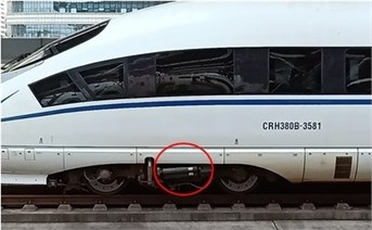
Fig. 1A hydraulic yaw damper used in the Chinese CRH 380 high-speed train
The flow continuity equation of the damper during extension and compression can be respectively formulated by:
where , are total flow loss and discharged flow from the complete-valve-system. In formulating , the total flow loss model introduced in [11] can be used.
In addition, because a four-stage complete-valve-system [11, 12] is used in the yaw damper, so the pressure-flow characteristics of the complete-valve-system would be formulated by:
where , are respectively diameters of constant orifices in the valve 1 and 4, is discharge coefficient, is oil density, is the fourth typical speed, , , are spring stiff nesses of the valve 2, 3 and 4, , , ~ are pressures of the inner tube, back pressure in the outer tube and set pressures of the valve 1-4, ~ are respectively opening heights of the valve 2-4, ~ are respectively set pressure deviations of the valve 1-4.
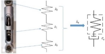
As illustrated by Fig. 2, equivalent stiffness of the hydraulic damper comprises of the rubber attachment stiffness and the oil stiffness , so is formulated by:
Fig. 2Equivalent stiffness model of hydraulic damper
The oil stiffness can be described by:
where , are respective dynamic elasticity modulus and elasticity modulus at initial conditions of the oil, , are respectively working pressure of the damper and standard atmospheric pressure, is entrapped air ratio in the damper fluid, is the working pressure action area, is volume of the pressure chamber of the damper, thus, it can be formulated by:
for the extension stroke of the damper, and:
for the compression stroke, where is the displacement of the damper, and are heights of inner tube and piston.
Asa result, the above equations are coupled to obtain a full-parametric model, which describes the DDC of the hydraulic damper.
2.2. Simulation and experimental validation
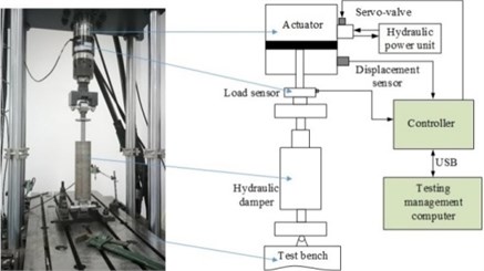
DDC of the hydraulic damper is simulated in MATLAB environment by means of the established full-parametric model, bench testing of the hydraulic damper, as illustrated in Fig. 3, is also conducted by a MTS test stand with hydro-servo excitation system [12], thus, the built full-parametric DDC model of the hydraulic damper is validated [12], it is appropriate for damper parameter influence analysis.
Fig. 3Testing the damping characteristics in a MTS test rig
3. Results and discussion
3.1. Effect of attachment stiffness on DDC
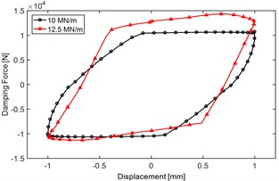
Parameter influence on DDC of the hydraulic yaw damper is simulated in MATLAB environment by means of the built mathematical model. Fig. 4 illustrates the influence of rubber attachment stiffness on main DDC indices.
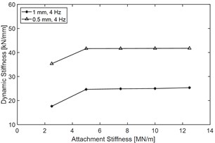
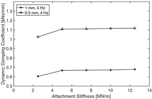
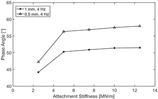
Fig. 4Effect of rubber attachment stiffness k0 on main DDC indices of the yaw damper: a) force-displacement performance when with different rubber attachment stiffness, test condition: excitation frequency 2 Hz and amplitude 1 mm, b) dynamic stiffness vs. k0, c) dynamic damping coefficient vs. k0 and d) phase angle vs. k0
a)
b)
c)
d)
Fig. 4(a) demonstrates that variations of rubber attachment stiffness would cause obvious change of Force-displacement characteristics. Fig. 4(b), (c) and (d) show that when attachment stiffness is less than 7.5 MN/mm, with the increasing of , all of the dynamic indices will increase obviously, however, when the attachment stiffness exceeds 7.5 MN/mm, with the increasing of , the dynamic stiffness and the dynamic damping coefficient both remain level, the phase angle will increase slightly.
Table 1 shows the main DDC indices and its change rate when increases from 2.5 MN/mm to 10 MN/mm, and it demonstrates that increasing of attachment stiffness would increase almost all of the main dynamic damping indices regardless of the excitation amplitude, for example, when the excitation amplitude is 1 mm, and increases from 2.5 MN/mm to 10 MN/mm, the dynamic stiffness would increase by 41.7 %, the dynamic damping coefficient would increase by 11.3 %, and the phase angle would increase by 16.4 %.
Table 1The influence of attachment stiffness k0 on main DDC indices and its rate of change
Indices | Excitation amplitude (mm) | 2.5 MN/m | 10 MN/m | The rate of change (%) |
Dynamic stiffness (kN/mm) | 0.5 | 35.74 | 41.7 | ↑16.7 |
1 | 17.64 | 25 | ↑41.7 | |
Dynamic damping coefficient (kNs/mm) | 0.5 | 1.025 | 1.115 | ↑8.8 |
1 | 0.604 | 0.627 | ↑11.3 | |
Phase angle (°) | 0.5 | 47.22 | 57.54 | ↑21.9 |
1 | 44.19 | 51.42 | ↑16.4 |
3.2. Effect of air entrapment in the fluid on DDC
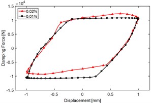
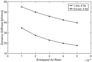
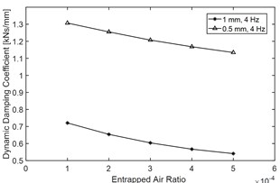
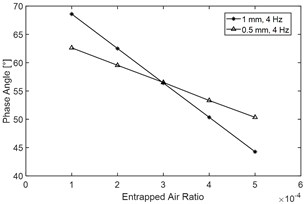
Fig. 5 demonstrates the effect of entrapped air ratio on main indices of the DDC. Fig. 5(a) illustrates that variation of would lead to obvious change of Force-displacement characteristics, Fig. 5(b), (c) and (d) also show that with the increasing of , all of the DDC indices will decrease apparently, especially the phase angle will drop obviously, thus, it indicates that air entrapment of the fluid would apparently decrease the elasticity modulus of the fluid and weaken the dynamic performance of the damper.
Table 2 quantification ally compares the main DDC indices and its change rate when entrapped air ratio increases from 0.01 % to 0.04 %, and it demonstrates that increasing of would decrease almost all the main dynamic damping indices regardless of the excitation amplitude, for example, when the excitation amplitude is 1 mm, and ɛ increases from 0.01 % to 0.04 %, the dynamic stiffness would drop by 42.8 %, the dynamic damping coefficient would decrease by 21.4 %, and the phase angle would drop by 26.6 %.
Fig. 5Effect of entrapped air ratio ε on main DDC indices of the hydraulic yaw damper: a) an illustration of force-displacement characteristics when with different entrapped air ratio, test condition: excitation frequency 2 Hz and amplitude 1 mm, b) dynamic stiffness vs. ε, c) dynamic damping coefficient vs. ε and d) phase angle vs. ε
a)
b)
c)
d)
Table 2The effect of entrapped air ratio ε on main DDC indices and its rate of change
Indices | Excitation amplitude (mm) | 0.01 % | 0.04 % | The rate of change (%) |
Dynamic stiffness (kN/mm) | 0.5 | 55.02 | 42.36 | ↑16.7 |
1 | 34.65 | 19.83 | ↑41.7 | |
Dynamic damping coefficient (kNs/mm) | 0.5 | 1.307 | 1.168 | ↑8.8 |
1 | 0.721 | 0.567 | ↑11.3 | |
Phase angle (°) | 0.5 | 62.62 | 53.32 | ↑21.9 |
1 | 68.59 | 50.35 | ↑16.4 |
4. Conclusions
A full parametric model describing the DDC of a railway vehicle hydraulic damper is built and experimentally validated. The influence of mounting and fluid parameter on DDC of the hydraulic damper is simulated by means of the mathematical model.
Increasing of would increase almost all the main dynamic damping indices regardless of the excitation amplitude, when the amplitude is 1 mm, and increases from 2.5 MN/mm to 10 MN/mm, the dynamic stiffness would increase obviously by 41.7 %.
With the increasing of , all of the dynamic damping characteristic indices will decrease apparently, when the excitation amplitude is 1 mm, and ɛ increases from 0.01 % to 0.04 %, the dynamic stiffness would drop remarkably by 42.8 %. Thus, the analysis result implies that air entrapment of the fluid would apparently decrease the elasticity modulus of the fluid and weaken the DDC of the damper.
References
-
G. Z. Yang and F. T. Wang, Hydraulic Damper of Railway Vehicle. Beijing, China: China Railway Press, 2003.
-
European Standard En13802, “Railway applications-suspension components-hydraulic damper,” CEN-CENELEC Management Centre, Brussels, Belgium, 2013.
-
W. Wang, Y. Liang, W. Zhang, and S. Iwnicki, “Effect of the nonlinear displacement-dependent characteristics of a hydraulic damper on high-speed rail pantograph dynamics,” Nonlinear Dynamics, Vol. 95, No. 4, pp. 3439–3464, Mar. 2019, https://doi.org/10.1007/s11071-019-04766-4
-
X. Z. Zhou, M. R. Chi, H. X. Gao, D. X. Yang, and J. S. Qin, “Research on calculation method of hydraulic damper dynamic characteristics,” (in Chinese), Electric Drive for Locomotives, Vol. 4, pp. 88–91, 2018, https://doi.org/10.13890/j.issn.1000-128x.2018.04.115
-
H. B. Ou, Y. Wang, and C. Huang, “Experimental study on dynamic characteristics of yaw damper,” (in Chinese), Mechanical Engineering and Automation, No. 5, pp. 51–52, 2016.
-
Q. Yuan, C. Lu, C. L. Hong, T. Y. Xu, and C. B. Xu, “The study on dynamic feature of yaw damper of EMUs,” (in Chinese), Chinese Journal of Construction Machinery, Vol. 15, No. 6, pp. 492–496, 2017, https://doi.org/10.15999/j.cnki.311926.2017.06.005
-
A. C. Mellado, E. Gomez, and J. Vinolas, “Advances on railway yaw damper characterisation exposed to small displacements,” International Journal of Heavy Vehicle Systems, Vol. 13, No. 4, p. 263, 2006, https://doi.org/10.1504/ijhvs.2006.010583
-
A. Alonso, J. G. Giménez, and E. Gomez, “Yaw damper modelling and its influence on railway dynamic stability,” Vehicle System Dynamics, Vol. 49, No. 9, pp. 1367–1387, Sep. 2011, https://doi.org/10.1080/00423114.2010.515031
-
C. Huang and J. Zeng, “Dynamic behaviour of a high-speed train hydraulic yaw damper,” Vehicle System Dynamics, Vol. 56, No. 12, pp. 1922–1944, Dec. 2018, https://doi.org/10.1080/00423114.2018.1439588
-
W. L. Wang, D. S. Yu, Y. Huang, Z. Zhou, and R. Xu, “A locomotive’s dynamic response to in-service parameter variations of its hydraulic yaw damper,” Nonlinear Dynamics, Vol. 77, No. 4, pp. 1485–1502, Sep. 2014, https://doi.org/10.1007/s11071-014-1393-2
-
W. L. Wang, Y. Huang, X. J. Yang, and G. X. Xu, “Non-linear parametric modelling of a high-speed rail hydraulic yaw damper with series clearance and stiffness,” Nonlinear Dynamics, Vol. 65, No. 1-2, pp. 13–34, Jul. 2011, https://doi.org/10.1007/s11071-010-9871-7
-
S. Zhu, “A study on the dynamic damping characteristics of a high-speed train hydraulic damper,” (in Chinese), Master’s Degree Thesis, Guangdong University of Technology, China, 2020.
About this article

The authors would like to acknowledge funding from the National Natural Science Foundation of China (NSFC) under Grant No. 11572123 and the Research Funding for High-level Talent of Dongguan University of Technology under Project No. KCYXM2017026.
