Abstract
A shearing motion inevitably occurs along the creep distance on the macroscopic surface of two objects before the friction transformed from static into kinetic state when they come into contact each other. In the process of shearing, it will creep to the characteristic distance before slipping on the supporting surface, then proceed to slip on the contacting points, such an alternating motion between contact surfaces is prone to result in rattling noise. In this paper, the mechanism of the automotive rattling or clicking noise produced in bolted joints surface will be addressed mathematical through the characteristic distance of stick-slip model. Finally, it is suggest that how to prevent these noises in the early design phase.
1. Introduction
In recent years, squeak and rattle has become an essential indication to determine the quality of automobiles. Friction-induced noise has been discovered to be dependent on the contact material at the interface. It was discussed by Song and Yan [1] in that the stick-slip friction movement of the interface from two aspects of macro-scale and micro-scale. Berman et al. [2] introduced the origins and characteristics of three different stick-slip frictional motions, explained the application conditions of each model, and utilized experimental methods to demonstrate that changes in associated factors affect each stick-slip motion model. Liu et al. [3] started with stick-slip friction in two types of mechanical systems, and then combined it with particular research goals to investigate the causes of stick-slip friction from the mechanical model, problem emphasis, and research methods.
In reality, the friction phenomenon associated with the micro movement distance will occur in the moving state of automobile chassis components, that is, the two contact surfaces creep a certain distance from each other under the action of external load, accumulating enough energy, release it, and begin sliding, resulting in a lot of noise in the process of sliding, which is the rattling noise mentioned in this article. Rabinowicz introduced the idea of characteristic distance. The concept assumes that contact between macro rough surfaces achieves by the adhesion of surface asperities.
However, none of the above-mentioned studies on stick-slip motion involves the research related to noise. This article focuses on the basic principles of stick-slip friction caused by the annoying noise caused by the movement of auto parts. And, throughout the design phase, the main factors that impact the movement are determined via analysis, in order to eliminate rattling noise created by this sort of stick-slip movement.
2. Mechanical model of stick-slip motion
The stick-slip movement may be found in almost every aspect of people’s daily life. In short, the mechanical model generated by this type of motion can typically be reduced to the spring mass model. A typical single degree of freedom stick-slip motion model [4] is shown in Fig.1.
Fig. 1Single degree of freedom stick-slip mechanical model
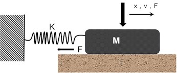
It is not difficult to conclude from the preceding model that when we attempt to simulate the stick-slip friction between the two friction surfaces with the friction force acting between the two friction surfaces, we will quickly realize that the stick-slip phenomenon is dependent not only on , but also on other system parameters such as the inertia, stiffness , and mass of the moving parts. A necessary requirement for stick-slip is that the static friction force (the force necessary to initiate sliding) is larger than the dynamic friction force, taking into consideration the properties of the friction surface itself (the force during the sliding process).
Assuming that the contact interface’s friction type is dry friction and that its friction characteristics follow the Coulomb Friction Law, the motion of the mass in Fig. 1 is determined by the motion Eq. (1):
where, in the formula, is the spring stiffness; is the relative displacement of the mass; is the friction between the two mutually contacting surfaces.
When the system is in Slip mode, or relative sliding, the friction between the contact surfaces is proportional to the relative sliding speed. At this point, the friction may be represented as:
where, is the sliding friction coefficient, is the acceleration of gravity, and is the symbolic function, which represents the direction of relative motion speed.
When the system is in stick mode, that is , in viscous state, there is no relative motion between the contact surfaces, then the acceleration of the mass is equal to that of the sliding, that is , the motion Eq. (3) can be written as:
As a result, the condition of the mass and the contact surface varies continually but does not exceed the maximum static friction. If the motion speed of the contact surface is somehow optimally fixed in the preceding motion system, then:
To summarize, while the mass is in the viscous mode, it interacts with the contact surface until the time indicates the end of the stick mode. Before reaching this point, the viscous friction increases to the maximum friction in the viscous state as the spring force increases.
3. Mechanism of characteristic distance stick-slip
There are numerous more comprehensive models of stick-slip friction based on the above spring mass model, including contact surface roughness, sliding speed, and variable relaxation durations. Various models are based on the mechanical properties of surfaces or interacting objects. Each model is appropriate for a certain practical situation.
The stick-slip model presented in this article refers to the sliding of one solid relative to the other. It is a unique model that incorporates the characteristic distance [6]. Meanwhile including time , which is the characteristic time required to increase the adhesion strength of two rough surfaces after contact. Rabinowicz [7] proposed the concept around the end of the last century. It demonstrates that two rough macro surfaces are joined by a micro rough body with a characteristic distance .
The surface will creep to a specific distance before sliding occurs during the shearing process. This is relevant to the system's Deborah number [5], which relates the material’s intrinsic relaxation time with the time scale of movement and measurement in the system. The essence of this type of stick-slip motion is that during the shear process, each surface must creep for a specific distance, i.e. the size of the contact point, and then the surface continues to slide, but the friction -dynamic friction, is lower than the initial friction - static friction.
The reason for the reduction in friction is that the new asperity connection's formation speed should be as fast as the old asperity connection's fracture speed, but the new asperity connection’s time-varying adhesion and friction will be lower than that of the old asperity connection [5, 12-14]. As a consequence, the friction force remains high throughout the creeping stage of sliding, but after the surface moves the characteristic distance, the friction force rapidly reduces to the dynamic friction value, as illustrated in Fig. 2.
Fig. 2Schematic of characteristic distance stick-slip model
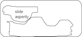
a) Initial contact 0
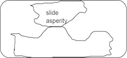
b) Fully contact
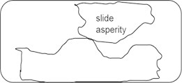
c) Continuous contact
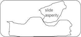
d) In-depth contact
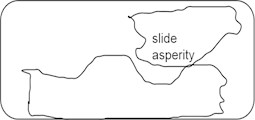
e) Sliding separation
As seen in Fig. 1, given specified values of , , and speed , any system with dynamic friction smaller than static friction or a system with a negative slope on a segment of its F-V curve would display regular stick-slip motion. The significance of critical velocity is demonstrated by the continuous stick-slip system. In the creep-dominated zone (low sliding velocity , high stiffness value ), and in the inertia-dominated region [8,] the critical velocity changes with altering .
Fig. 3Principle of characteristic distance stick-slip
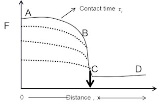
According to the above analysis, the static friction force varies with the normal load and the speed of the shear surface, implying that the characteristic distance will equally vary with the load and speed. The distance can be calculated experimentally by multiplying the average time required for conversion from to by the shear drive speed . In line with the test findings, the critical distance of the steel surface is less than 10-3 cm [9].
4. Rattle noise up-front design prevention
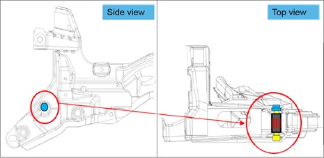
A car’s chassis is essentially a whole structure that is connected by various parts via a bolt structure, for example, rear axle swing arm, longitudinal beam as well as upper and lower control arm. The control arm structure as depicted in Fig. 4. If a relative stick-slip motion occurs between two components, it will inevitably produce relatively loud noise due to the stored energy release when the motion switch from maximum static friction to kinetic friction. Therefore, the critical circumstances (slide speed, preload, and sliding distance) that create this noise are critical in preventing stick-slip motion between chassis connection structures.
Because of the relative motion between the contact surfaces, this type of vehicle control arm is tend to exhibit stick-slip behavior. The contact surface's elastic deformation will store energy. When the static friction exceeds the dynamic friction, this energy is released, resulting in abnormal noises that make people feel unpleasant. The appropriate force analysis may be done in the early stages of the design using the stick-slip model described in section 2 above, such that the mounting surface of the bolt is under varied operating circumstances always be less than the distance when the maximum static friction is obtained, so as to achieve the purpose of eliminating the rattling noise.
Fig. 4Typical vehicle control arm bolted joints structure
5. Stiffness optimization of the bolted bracket
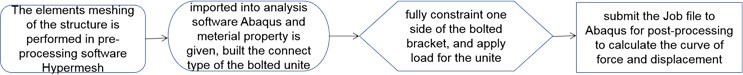
FEA methodology for bolted joints analysis [6, 13] could well be utilized to effectively calculate the force necessary to overcome the deformation of bolt mounting support, as illustrated in Fig. 5. The Hypermesh and Abaqus software are utilized to simulate the stiffness of the bolted mounting surface of an vehicle chassis control arm, the detailed process as seen below flowchart Fig. 6.
Fig. 5Stiffness simulation analysis of control arm bracket
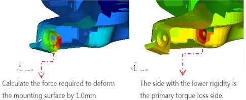
Fig. 6Bolted bracket stiffness FEA process flowchart
Second, the force necessary to eliminate the bracket installation gap could be determined on the basis of the design tolerance, namely the static stiffness corresponding to displacement - the gap, is able to be obtained, Fig. 7 shows the relation between static stiffness and displacement. According to the mechanical model of stick-slip motion in Fig. 1, since the amplitude of stick-slip oscillation must usually be greater than the characteristic distance, the method of increasing the stiffness of the bracket is used all through design to eliminate stick-slip motion [10].
Fig. 7The relation between stiffness and displacement
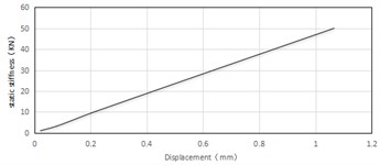
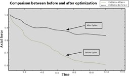
Fig. 8Comparison of before/aft force optimization
Previous study indicates that the critical distance between steel and iron is not greater than 10-3 cm [11]. It can be observed that the maximum distance of relative movement of the joining surface could well be computed using the outcomes of the bolted joint stiffness analysis. If the requirements are not reached, the torque loss can be decreased by weakening the installation structure or redesigning the dimensional tolerance so that the stick-slip movement is eliminated by minimizing the distance - making it less than the critical distance.
6. Clamping force optimization of the bolt
When the static load and working temperature fluctuate slightly, the two supporting surfaces of the threaded connection generally do not move relative to each other [14, 15]. If the coupling position is subjected to more impact, vibration, or unexpected load changes, the friction between the screw pairs will decrease or disappear instantly, resulting in an unexpected sound. As a solution, to prevent any relative movement between the two components connected by the screw connection, the design can also include metal gaskets as shown part (a) in Fig. 9, typically 0.2-0.3 mm, and knurling on the surface as seen in Fig. 9 part (b)to render the mounting surface more rough [14], as well as double nuts illustrated in part (c).
Fig. 9Metal mounting surface treatment patterns
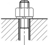
a) Metal spacer
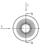
b) Knurling surface
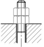
c) Double nuts
As a matter of fact, the fundamental purpose of countermeasures above have been taken is to improve the clamping force of bolts. The mathematical principle wherein lies in below equation:
where, represents the transverse load on each bolt; is the number of bolts; is the total transverse load. For bolted joints, the maximum friction created on the mounting surface must be greater than or equal to the transverse load after the connection has been preloaded. Assuming that the clamping force necessary for each bolt is , the equilibrium condition is:
Thus, it can be obtained the clamping force , as shown in Eq. (8):
where, is the frictional coefficient of mounting surface; is the number of joint surface, 2 in this article case; is the coefficient of slip-resistance, here the 1.1~1.3.
Subsequently, ultrasonic measuring equipment is used to check the torque attenuation before and after knurling surface treatment is implemented. The axial force of the control arm bolt has been greatly improved after performance degradation testing, as indicated in the Fig. 8 plot.
7. Conclusions
Stick-slip between contact surfaces can be eliminated by making the shear distance smaller than the characteristic distance, causing the contact time between the connecting surfaces to creep longer, increasing the shearing distance while maintaining the relative speed between the bolt connection surfaces constant. Because bolted joints are prone to stick-slip, resulting in annoying noises such as rattling noise, measures such as optimizing the deformation of the bolt mounting bracket and the bolt clamping force are implemented after verification and analysis in the early stages of design to avoid rattle on the bolt mounting surface.
References
-
B. J. Song and S. Z. Yan, “Research progresses on interfacial stick-slip frictions,” China Mechanical Engineering, Vol. 28, No. 13, pp. 1513–1522, 2017, https://doi.org/10.3969/j.issn.1004-132x.2017.13.001
-
A. D. Berman, W. A. Ducker, and J. N. Israelachvili, “Origin and characterization of different stick−slip friction mechanisms,” Langmuir, Vol. 12, No. 19, pp. 4559–4563, Jan. 1996, https://doi.org/10.1021/la950896z
-
L. L. Liu, H. Z. Liu, H. R. Zhao, and M. Q. Yao, “Review on stick-slip friction in mechanical system,” Mechanical Science and Technology for Aerospace Engineering, Vol. 35, No. 5, pp. 662–671, 2016, https://doi.org/10.13433/j.cnki.1003-8728.2016.0502
-
Z. Yang, J. Zhang, M. Shen, X. Wan, B. Zeng, and C. Yang, “Analysis of stick-slip induced abnormal click noise at transmission output end and the corresponding improvement measures,” Noise and Vibration Control, Vol. 39, No. 3, pp. 128–132, 2019.
-
P. E. Rossouw, L. S. Kamelchuk, and R. P. Kusy, “A fundamental review of variables associated with low velocity frictional dynamics,” in Seminars in Orthodontics, Vol. 9, No. 4, pp. 223–235, Dec. 2003, https://doi.org/10.1016/j.sodo.2003.08.003
-
D. J. Segalman, “Modelling joint friction in structural dynamics,” Structural Control and Health Monitoring, Vol. 13, No. 1, pp. 430–453, Jan. 2006, https://doi.org/10.1002/stc.119
-
E. Rabinowicz, “The intrinsic variables affecting the stick-slip process,” Proceedings of the Physical Society, Vol. 71, No. 4, pp. 668–675, Apr. 1958, https://doi.org/10.1088/0370-1328/71/4/316
-
E. Rabinowicz, “Friction and wear of materials,” Wear, Vol. 8, No. 6, p. 491, Nov. 1965, https://doi.org/10.1016/0043-1648(65)90145-6
-
J. B. Sampson, F. Morgan, D. W. Reed, and M. Muskat, “Studies in lubrication: XII. Friction behavior during the slip portion of the stick‐slip process,” Journal of Applied Physics, Vol. 14, No. 12, pp. 689–700, Dec. 1943, https://doi.org/10.1063/1.1714948
-
F. Heymann, E. Rabinowicz, and B. G. Rightmire, “Friction apparatus for very low‐speed sliding studies,” Review of Scientific Instruments, Vol. 26, No. 1, pp. 56–58, Jan. 1955, https://doi.org/10.1063/1.1771241
-
C. H. Scholz and J. T. Engelder, “The role of asperity indentation and ploughing in rock friction – I,” International Journal of Rock Mechanics and Mining Sciences and Geomechanics Abstracts, Vol. 13, No. 5, pp. 149–154, May 1976, https://doi.org/10.1016/0148-9062(76)90819-6
-
J. H. Dieterich, “Time-dependent friction and the mechanics of stick-slip,” Pure and Applied Geophysics PAGEOPH, Vol. 116, No. 4-5, pp. 790–806, 1978, https://doi.org/10.1007/bf00876539
-
R. S. Fernandes, R. Bortolussi, S. Delijaicov, and J. Ferreira, “Modeling stick-slip in bolted joint tightening process,” International Journal of Pressure Vessels and Piping, Vol. 183, p. 104102, Jun. 2020, https://doi.org/10.1016/j.ijpvp.2020.104102
-
H. Gong, X. Ding, J. Liu, and H. Feng, “Research review on loosening mechanisms and anti-loosening methods of threaded fasteners,” Journal of Mechanical Engineering, Jun. 2021.
-
M. X. Yin and S. J. Shi, “The analysis of screw connection and the torque degeneration,” Structure and Environment Engineering, Vol. 40, No. 4, pp. 31–35, 2013, https://doi.org/10.3969/j.issn.1006-3919.2013.04.00
About this article

