Abstract
A multi-body dynamic model of the suspension system was built in this paper. The vibration displacement of wheel center on running pavement was obtained by experiment and applied it into the multi-body dynamic model to simulate actual operation conditions. Then, vibration acceleration of suspension axle was extracted and compared with the experimental result. The dynamic load acting on the suspension jounce bumper was acquired by the multi-body dynamic model and applied to the finite element model of the jounce bumper. Then, the stress in the loading position was computed and imported into NASTRAN to conduct fatigue durability analysis of the jounce bumper. Afterwards, the dynamic characteristic and fatigue life of the jounce bumper were optimized based on the improved genetic algorithm. Finally, vibration isolation ratios of the suspension system before and after optimization were compared to verify optimization effect. In this way, the suspension system has a better dynamic characteristics and higher fatigue life.
1. Introduction
As the elastic connecting link in a vehicle structure, suspension was a complicated mechanical system, which was composed of numerous parts. It directly affected the ride comfort and operation stability of the vehicle. While the running speed of the vehicle increased, the requirements for ride comfort and operation stability of vehicles was increasingly high. The dynamic study on the suspension system has attracted wide attention [1]. Macpherson suspension creatively combined shock absorber with helical spring together, and they were mounted on the front axle. This suspension had a simple structure, less occupation space and good maneuverability. Therefore, it was widely used in the front axle of vehicles. The multi-link suspension had a compact structure, and its wheel occupied a relatively small area of the body [2]. As a result, it made the rear space of vehicle larger. In addition, it had good maneuverability and stability. However, it was usually used on the rear axle of the luxury vehicle.
However, there were also defects in the Macpherson suspension which was widely used. It can’t provide enough support to the lateral force. Therefore, once the vehicle was making a turn, it will have a roll easily. As a result, it was necessary to re-design the dynamic characteristic of the suspension based on this problem.
The vehicle designers have taken suspension optimization design as one of the key issues. Currently, optimization design of suspension is divided into two types. One type aims at realizing optimization via programming. The other type realizes optimize by virtual prototyping platform. The former one is tedious and complicated to operate, wherein elastoplasticity of the components is often neglected. The latter is convenient to operate. Pan [3] combined the least square method with the optimal control method to optimize Macpherson suspension, but they failed to consider the roll. The dynamic characteristics of Macpherson suspension were evaluated by Beale. However, during building the simulation model, the suspension was seemed as a rigid body, which was not consistent with the actual situation. Sancibrian optimized the kinematics of the suspension system by the multi-objective optimization algorithm, but the process had not been verified by experiments. Therefore, the final results may not be accurate. Chen [4] applied genetic algorithm in optimization for five-link suspension to analyze the kinematic characteristics of the wheel camber during the bouncing process of the wheels. However, the optimization of five-link suspension system is mainly single object optimization at present. In the above researches, fatigue life of suspension is not considered comprehensively and several major parameters cannot be harmonized very well. In addition, most optimization process is not verified through experiments, and the roll of Macpherson suspension was still not improved.
Considering the roll problem of Macpherson suspension, Geely Company has designed a new type front suspension. The suspension was similar to the structure of Macpherson suspension, but it effectively solved the problem of the roll. However, the dynamic characteristic and fatigue life of this suspension were poor. Therefore, these problems of the proposed new type suspension were researched and optimized in this paper in detail. The paper built a multi-body dynamic model of suspension system. The vibration displacement of wheel center on running pavement is obtained by experiment and applied it into the multi-body dynamic model to simulate actual working conditions. Then, we extracted the vibration displacement of a point at the suspension and compared it with the experiment result in order to verify the accuracy of the multi-body dynamic model of suspension. The dynamic load acting on the suspension jounce bumper was acquired by the multi-body dynamic model and applying it to a finite element model of the jounce bumper. Then, the stress in the loading position was computed, and it was imported into NASTRAN to conduct fatigue durability analysis of the jounce bumper. Afterwards, the dynamic characteristic and fatigue life of the jounce bumper were optimized based on genetic algorithm. At last, vibration isolation ratios of the suspension system before and after optimization were extracted for comparison to verify optimization effect. The paper innovatively combined dynamic analysis of suspension with assessment of fatigue life. In this way, the suspension system could possess a better dynamic characteristics and high fatigue life.
2. The background theory
Fatigue referred to development of local and permanent structural change occurring in cracked or completely fractured materials after sufficient cyclic perturbations due to perturbation stress on a point or some points. Generally, the cyclic load causing fatigue failure was less than the “safe” load according to static strength analysis. Traditional static strength analysis methods can’t solve fatigue problems. Fatigue was one of the main causes for structural failure. It was the main factor that needs to be considered in structural reliability experiment [5].
High-cycle fatigue was also deemed as stress fatigue because it was mainly determined by stress amplitude. Under this condition, the cyclic stress on the material was far less than its yield limit. The cycle-number was large before damage, in general, it was bigger than 105-106. When the cyclic stress was small, elastic strain became dominant. The elastic stress will transform into plastic stress when it gradually increased to a certain extent. Under this condition, the plastic strain started to become dominant gradually. Generally, the stress level was low under high-cycle fatigue. Under this condition, the material deformation was within elastic range, and the stress was in direct proportion to the strain. Generally, the fatigue properties of the materials can be described by “stress-cycle-number” curve.
As for the high-cycle fatigue problem, the so-called S-N method was used to analyze life cycle based on the stress of the materials or parts. In this method, the fatigue life was mainly calculated according to the stress or strain distribution of the parts provided by the finite element model. Such analysis was conducted based on the fatigue characteristic of the materials. This method didn’t explicitly distinguish the occurrence and propagation of the cracks. It was mainly used for predicting the entire life of large damage or fracture occurring on the parts. It can estimate the entire life before abrupt failure of the parts.
Linear cumulative damage theory referred to that the fatigue damage can be linearly superimposed [6, 7]. The representative theory included Palmgren-Miner as well as modification Miner and relative Miner. Miner assumed that fatigue failure will occur when the energy absorbed by the sample reaches certain value. For instance, the limit value of absorbable energy before failure is , and the total circle number before failure is . When the circle number is, the energy absorbed by the sample will be The energy absorbed is in direct proportion to its circle number:
If the sample bears the load of , ,…, under different stress levels, and its fatigue life under each stress level will be , ,…, . Its circle number will be , ,…, , and the damage to the part is:
Under this condition, the absorbed energy reaches the limit value , and the fatigue failure occurs.
When the critical damage:
where “” stands for the safety coefficient of fatigue life. It is a critical damage value, which is determined by materials and safety requirements for fatigue life of a structural part. When 1, fatigue damages have already appeared. Hence, “” is a constant less than 1 in actual engineering problems. In the manuscript, “” was set to be 0.8 according to structure materials and life requirements of the suspension system.
Scholars’ further research on the critical damage shows that parts of the same kind have similar damage value under similar load spectrum. Therefore, life estimation can be carried out under similar load spectrum, i.e., relative Miner. Its expression is:
In the equation, is the damage and experiment value of the parts of the same kind under similar load spectrum [8, 9].
3. Suspension dynamics analysis
3.1. Research on suspension experiment
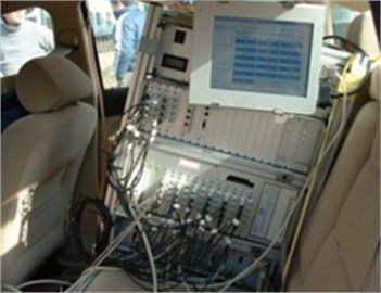
It was necessary to test vibration displacement of vehicle wheel center on a real pavement and applied it into a multi-body dynamic model of suspension. In this way, the suspension system can be simulated really. As shown in Fig. 1, two wheel center sensors were mounted on vehicle wheel center of the front suspension, respectively. Then, vehicle was travelling on the road at the speed of 20 m/s for 700 m distance. The testing process was shown in Fig. 2. The multi-channel data collection equipment was used to obtain the vibration displacement of wheel center, and it was then imported into test.lab to be processed. The final testing result was shown in Fig. 3.
Fig. 1Testing equipments of vibration displacement for vehicle wheel center

a) Testing equipments
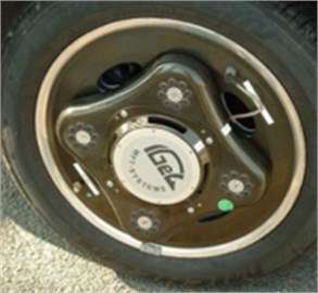
b) Wheel center sensor
Fig. 2Testing process of vibration displacement and acceleration
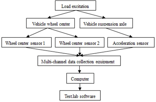
Fig. 3Vibration displacement of the wheel center
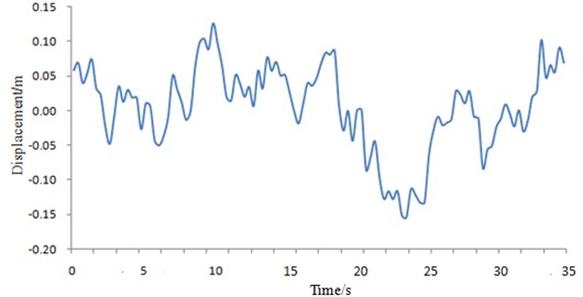
It was shown in Fig. 3 that the vibration displacement fluctuated irregularly when the vehicle traveled on a real pavement. The actual road condition was used as the excitation during the testing process. Then, this excitation was imported into the multi-body dynamic model of the suspension system. As a result, the research will be more realistic. If the constant vibration excitation was applied on the suspension system, there were some problems in the subsequent researches. Because this paper wanted to obtain the fatigue characteristic of the buffer block in the suspension system, it must require a cyclic excitation. If a sinusoidal excitation was applied on the suspension system, it was not consistent with the actual road condition. Therefore, this research may not have much significance in engineering. According to the above analysis, the research based on the actual road condition will be the most suitable.
3.2. Establishment and verification of multi-body dynamic model of suspension
The front suspension of the vehicle was simplified and modeled by a five-link mechanism in MotionView. The model of the link mechanism was built by rigid body. Models of the damper and the jounce bumper were built by flexible body. The link was a rigid hinge. The five-link mechanism could save space and had a better dynamic performance [10, 11]. The multi-body dynamic model of the front suspension is shown in Fig. 4.
Fig. 4Multi-body dynamic model of the front suspension
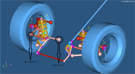
It was shown in Fig. 4 that the multi-body dynamic model of suspension was very complicated. It was necessary to verify reliability of the model through experiments. In this way, the accuracy of subsequent analysis could be ensured.
An acceleration sensor was mounted on the suspension shaft, as shown in Fig. 5. When the vibration displacement of vehicle wheel center was tested, the multi-channel data collection equipment was also used to obtain the vibration acceleration of the suspension shaft at the same time. And then it was imported into test.lab to be processed, the corresponding process was shown in Fig. 2. Testing results were compared with simulation results of multi-body dynamic model in Fig. 4, and comparison results were shown in Fig. 6.
Fig. 5Testing equipment of vibration acceleration on the suspension shaft
a) Testing equipments
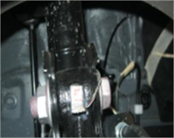
b) Acceleration sensor
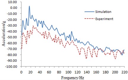
It was shown in Fig. 6 that trends and peaks of both experiment and simulation results coincided well within the frequency of 0-220 Hz. Within some frequency ranges, the experiment values were different from simulation values because the experiment only discussed vibration transmission and neglected structure-acoustic coupling. It was shown that the simulation model was reliable to analyze characteristics of suspension system.
Fig. 6Experiment and simulation comparison of the vibration accelerations at mounting point
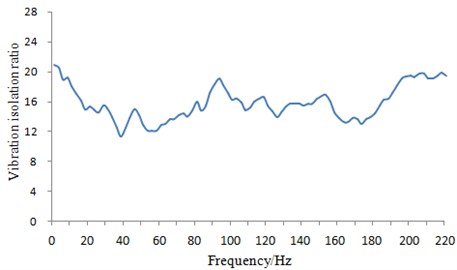
Based on the multi-body dynamic model, the vibration isolation ratio of suspension system was extracted for subsequent research as shown in Fig. 7. It was shown in the figure that the vibration isolation ratio changes with frequency in the whole research frequency range.
Fig. 7Vibration isolation ratio of suspension system
3.3. Establishment of finite element model for jounce bumper
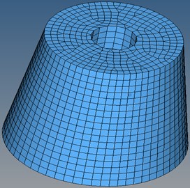
As an important component in a suspension system, a jounce bumper had to bear vibration transmitted by pavements and attenuates it. Therefore, it was very necessary to optimize and analyze its dynamic characteristics and fatigue life. The elasticity modulus of the aluminum-cast jounce bumper is 70,000 MPa. Poisson’s ratio is 0.33, and the density is 2.72×10⁻⁹t/mm3. Finite element mesh needed to be generated for the jounce bumper in order to analyze its fatigue life. The mesh was hexahedral mesh. The finite element model of jounce bumper was shown in Fig. 8.
4. Optimization design of the front suspension
The suspension system was a very complicated structure, and it had a lot of structural parameters. As a result, when optimization design was carried out, it was very necessary to which parameters were set as the design variables. Design of experiment (DOE) was one of the most widely method to determine the design variables. According to DOE, we can not only determine which variables had the largest influence on performance of the suspension system, but also control the variables in a certain range. As a result, response of the suspension system can be infinitely close to the actual value. It can construct an approximate model to replace the multi-body dynamic model with a large amount of computation. Finally, DOE was combined with genetic algorithm to obtain the suspension system which had the optimal performance.
Based on the above analysis, the toe-in curve of the vehicle was optimized to research the influence with the change of drag link ball joint coordinates on the dynamic force of the vehicle suspension under pavement displacement excitation. The variables were the and coordinates of the 2 ball joints. Their positions are as shown in Fig. 4. To ensure the static ride comfort of the suspension, the sum of the error square for the solver toe-in angle and the objective toe-in angle of the vehicle was set as the constraint, and it was less than 30. The optimization target was that the dynamic load acting on jounce bumper of suspension was minimal [14, 15].
Fig. 8Finite element model of jounce bumper
In this paper, the genetic algorithm was used to optimize and design the suspension system, and its necessity can be explained from the following aspects.
1) The traditional genetic algorithm was easy to be premature, and the local optimization ability was poor. In addition, the accuracy of results was not high. Although the results can quickly reach about 90 % of the optimal solution, it often required a lot of time to reach the optimal solution. This will undoubtedly increase the computational cost and reduce the computational efficiency. The improved genetic algorithm was proposed based on DOE method in this paper. This method was realized by adding DOE method into the iterative process, and it can quickly determine the design variable value and range. As a result, it made individuals of the population continue to mutate according to the required direction, which effectively improved the searching ability of genetic algorithm. Finally, it can accelerate the convergence speed and improve the computational efficiency.
2) If optimization design was directly conducted based on the suspension multi-body dynamic model, the iteration process will take a relatively long time and require higher computational cost due to the complexity of the multi-body dynamic model. The improved genetic algorithm proposed based on DOE method can not only quickly determine the design variables during the iterative process, but also obtain the approximate model to replace the multi-body dynamics model. As a result, the iterative process will be simple. There were a lot of papers to combine DEO method with genetic algorithm.
3) The research in this paper was based on Hyperstudy which was the commercial software. Genetic algorithm and DOE method were integrated into this software. When we wanted to use the improved genetic algorithm, only some parameters of this software should be modified, and it will not take a relatively long time to design a new program for optimization. As a result, it will obviously improve the computational efficiency, and it has been widely used.
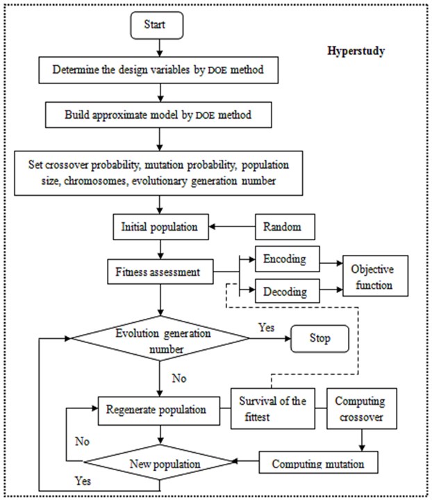
The improved genetic algorithm was used to optimize the suspension system, and the corresponding flow was shown in Fig. 9.
The detailed description of the optimization flow was as follows.
1) Chromosome coding. Each parameter of the suspension system was identified by DOE method and then the final design variable was obtained before searching. Finally, the target function was encoded into a binary string, and these strings were called as chromosome. The different combinations of these strings were the different search points of the search space.
2) Generation of the initial population. The initial population size was set to be 40.
3) Computing fitness. Fitness will directly affect the accuracy of the computational results. The objective function of the suspension system was taken as fitness value.
4) Selection. The individuals with stable fitness were selected as the new generation.
5) Crossover. The partial chromosomes of 40 individuals selected will be exchanged at a certain probability and thus 40 new individuals were generated. Crossover probability was set to be 0.9.
6) Mutation. 40 individuals selected were given a certain mutation probability to form a new generation. The mutation probability was set to be 0.05.
7) Judgment. It will be analyzed whether the new generation can meet the constraints. If it didn’t meet the constraints, the optimization will stop. Otherwise, the optimization will return to the third step to continue.
Fig. 9Optimization flow of suspension system
5. Results and discussions
Optimized analysis was carried out on the suspension by genetic algorithm. The change processes of the maximum dynamic load and the sum of the error square during optimization iteration process were shown in Fig. 10 and Fig. 11.
Fig. 10Iteration process of the dynamic load
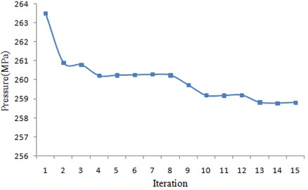
Fig. 11Iteration process of the sum of the error square
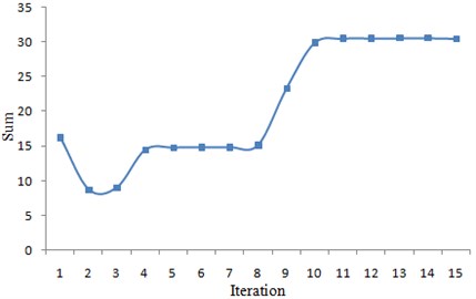
According to the figures, with the progress of iteration, the dynamic load on the suspension gradually decreased, while the sum of the error square gradually increased. It was shown that if the constraint for the sum of the error square was relaxed, the dynamic load on the suspension will be further reduced. When the iteration reached the 13th step, the iteration converged. The maximum value of the dynamic load became 258.53 MPa, and the sum of the error square was 29.80072.
Size of iterations should be as many as possible theoretically. However, for the time-consuming optimization process in this paper, its further optimization space was very small after sufficient repeated iterations. Therefore, the strategy of exchanging time for the limited optimization effect was unacceptable. Generally, a group of satisfactory solutions was enough.
Fig. 12Dynamic load on the jounce bumper before optimization
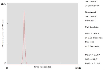
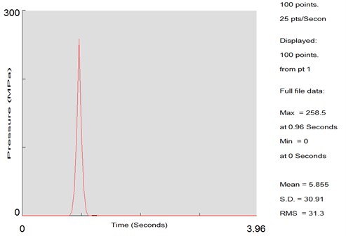
Dynamic loads which acted on the jounce bumper before and after the optimization were obtained through the mentioned analysis, as shown in Fig. 12 and Fig. 13. It was shown in the figures that the maximum dynamic loads acting on the jounce bumper before optimization was 263.5 MPa. The value changed into 258.5 MPa after optimization.
Fig. 13Dynamic load on the jounce bumper after optimization
In order to further verify optimization effect, vibration isolation ratios of the suspension system after optimization were extracted, which were compared with results before optimization (shown in Fig. 7), as shown in Fig. 14. It was shown in the figure that the vibration isolation ratio of the suspension system after optimization increased obviously when the frequency was over 30 Hz. In this way, and the suspension could attenuate vibration transmitted from pavement to the vehicle body and could also improve ride comfort.
Fig. 14Comparison of vibration isolation ratios of the suspension system before and after optimization
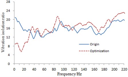
Fig. 15Fatigue life of the jounce bumper before optimization
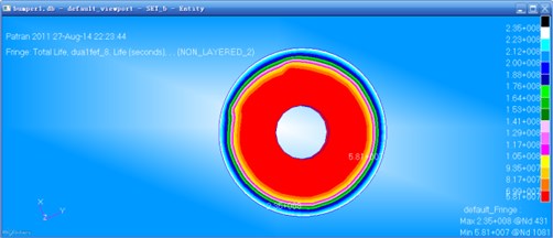
Dynamic loads in Fig. 12 and Fig. 13 were circulated with the circle of 4 s. They were applied to the finite element model of the jounce bumper. Therefore, fatigue lives of the jounce bumper before and after optimization could be respectively obtained, as shown in Fig. 15 and Fig. 16.
According to the nephogram of fatigue life, the position with the maximum fatigue life was improved at some extent. However, the change at position with the minimum life was not significant. Four elements on different places of the jounce bumper were taken from the exterior to interior to compare the fatigue life of these elements before and after optimization, as shown in Table 1.
Fig. 16Fatigue life of the jounce bumper after optimization
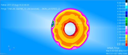
Table 1Comparison of fatigue life before and after optimization
Element | Life before optimization (h) | Life after optimization (h) |
1482 | 64510 | 118690 |
2059 | 73800 | 133340 |
2221 | 64510 | 133340 |
4993 | 73800 | 64510 |
6. Conclusions
The paper built a multi-body dynamic model of suspension system. The vibration displacement of wheel center on running pavement was obtained by experiment and then applied into the multi-body dynamic model to simulate actual working conditions. Then, we extracted the vibration displacement of a point at the suspension and compared it with the experiment result in order to verify the accuracy of the multi-body dynamic model of suspension. The dynamic load acting on the suspension jounce bumper was acquired by the multi-body dynamic model and applying it to a finite element model of the jounce bumper. Then, the stress in the loading position was computed, and it was imported into NASTRAN to conduct fatigue durability analysis of the jounce bumper. Afterwards, the dynamic characteristic and fatigue life of the jounce bumper were optimized based on genetic algorithm. Finally, vibration isolation ratios of the suspension system before and after optimization were extracted for comparison to verify optimization effect. The paper innovatively combined dynamic analysis of suspension with assessment of fatigue life. In this way, the suspension system could possess a better dynamic characteristics and high fatigue life.
References
-
Liu W. X. Automotive Design. Tinghua University Press, Beijing, 2001.
-
Lv Z. H. The analysis of rigid body kinematics and elastic kinematics for five-link suspension. Automotive Technology, 2002.
-
Pan J. G., Liu X. D. Optimal control method for optimization of vehicle suspension parameters. Transactions of the Chinese Society for Agricultural Machinery, 2005.
-
Chen K., Beale D. G. Base dynamic parameter estimation of a MacPherson suspension mechanism. Vehicle System Dynamics, Vol. 39, Issue 3, 2003, p. 227-244.
-
Sancibrian R., Garcia P., Viadero F., et al. Kinematic design of double-wishbone suspension systems using a multiobjective optimisation approach. Vehicle System Dynamics, Vol. 48, Issue 7, 2010, p. 793-813.
-
Chen X. K., Lin Y. Application of genetic algorithm in five-linkage suspension optimization. Automotive Technology, 2004.
-
Lin Y., Wen W. F., Zhang H. X., Fang C. L. A simulation of dynamics of vehicle multi-body system. CIDVC, 1990.
-
Chen K., Beale D. G. Base dynamic parameter estimation of a Macpherson suspension mechanism. Vehicle System Dynamics, Vol. 39, Issue 3, 2003, p. 227-244.
-
Mars W. V., Fatemi A. A literature survey on fatigue analysis approaches for rubber. International Journal of Fatigue, Vol. 24, Issue 9, 2002, p. 23-28.
-
Sharp R. S., Crolla D. A. Road vehicle suspension system design: a review. Vehicle System Dynamics, Vol. 16, Issue 3, 1987, p. 167-192.
-
Wood C. Integrated Durability Analysis of a Vehicle through Virtual Simulation. Masters of Science Master’s Thesis, Windsor University, 2003.
-
Lin S. H., Cheng C. G., Liao C. Y., et al. Experiments and CAE Analyses for Suspension under Durability Road Load Conditions. SAE Paper 2006-01-162, 2006.
-
Simionescu P. A., et al. Synthesis and analysis of the five-link rear suspension system used in automobiles. Mechanism and Machine Theory, Vol. 37, Issue 9, 2002, p. 815-832.
-
Dietz S., Netter H., Sachau D. Fatigue life prediction of a railway bogie under dynamic loads through simulation. Vehicle System Dynamics, Vol. 29, 1998, p. 385-402.
-
Gobbi M., Mastinu G., Doniselli C. Optimizing a car chassis. Vehicle System 140 Dynamics, Vol. 32, 1999, p. 149-170.
-
Vanderplaats G. N. Numerical Optimization Techniques for Engineering Design: With Applications. McGraw-Hill, New York, 1984.
-
Lu Pengming, He Limei, You Jinmin Optimization of vehicle suspension parameters based on comfort and tyre dynamic load. China Journal of Highway and Transport, Vol. 20, Issue 1, 2007, p. 112-117.
-
Goncalves J. P. C., Arabrosio J. A. C. Optimization of vehicle suspension systems for improved comfort of road vehicles using flexible multi-body dynamics. Nonlinear Dynamics, Vol. 34, 2003, p. 113-131.
About this article

Research is supported by the National Nature Science Fund of China (71301013), Humanity and Social Science Youth Foundation of Ministry of Education of China (13YJA790150).
