Abstract
At present, to meet the innervation and the comfort of cycling-trainers, the trend of deploying suspension system is still upwards. However, there is no reliable dynamic model for cycling-trainers equipped with suspension systems, and the influence of the suspension damping on the dynamic responses needs to be explored. In this paper, based on a commercially available cycling-trainer with suspension systems, a non-linear dynamic model of trainer-human coupled system was established. According to the bench test, the damping coefficient of suspension dampers was measured. By the cycling test, the dynamic model was validated. The test values of the vertical acceleration of the human lower trunk are in agreement with the simulation values, in which the maximum deviation is less than 15.0 % and the root mean square deviation is less than 8.0 %. Based on the model, the influences of the damper damping on the dynamic responses were analyzed. The results show that the influence laws of the suspension damping characteristics on the human body responses vary greatly under the different riding frequencies, and an optimal damping exists to avoid excessive fatigue caused by vibration under the medium and low frequency riding conditions. The established model and the revealed rules can provide useful reference for the suspension design and optimization of cycling-trainers.
Highlights
- A non-linear dynamic model of trainer-human coupled system was established
- The influence laws of the suspension damping characteristics on the human body responses vary greatly under the different riding frequencies
- An optimal damping exists to avoid excessive fatigue caused by vibration under the medium and low frequency riding conditions
1. Introduction
With the vigorous development of the national fitness activities, the work of the national fitness is increasingly valued and supported by the society, and the indoor fitness is more and more popular. As one of the main indoor fitness equipments, the cycling-trainer can effectively prevent the degeneration of the human skeleton and increase the function of lower limbs. Moreover, it is not affected by climate, time, and location. It has become one of the popular exercise tools [1]. With the improvement of people’s living standard and the change of people’s life concept, people put forward higher requirements for the motion and comfort of cycling-trainers besides the safety requirement [2]. At present, to meet the innervation and comfort of cycling-trainers, the trend of deploying suspension system is still upwards [3].
In order to improve the fitness effect, people have carried out relevant research from different angles of cycling-trainers, including ergonomics, human-computer interaction, human kinematics, and dynamics, etc. [4, 5]. By recording the data of heart rate and power, Mohammadi-Abdar et al. analyzed the changing rules of sports biomechanics and physiological characteristics of the rehabilitation fitness bikes users [6]. Mestre et al. conducted a detailed study on the correlation between virtual reality and exercise effect based on 12 college students’ cycling tests [7]. The pedal force, the hip pressure, and the muscle activity of lower limbs of cyclists were measured by Verma et al. [8]. The results showed that pedal force and the hip pressure changed approximately periodically during cycling, and there are maximum peak and minimum forces. Tsai et al. studied the power-aided control of an exercise bike [9]. Yen researched the riding seat position of fitness bikes on the comfort [10]. Chang et al. encouraged obese students with intellectual disabilities to engage in pedaling an exercise bike combined with environmental stimulation [11]. These studies provide useful references for the fitness effect by cycling-trainers. They also provide good theoretical support for the design, simulation, and optimization of cycling-trainers. The previous relevant investigations [12-14] provide references for the damping matching of suspensions for cycling-trainers. In order to improve comfort, Dow et al studied the vibration reduction of E-bikes [15]. Kociolek et al. analyzed the head and neck vibration exposure from a quad bike [16]. Munera et al. analyzed the rider dynamic response to vibration in cycling [17]. Gao et al. researched the effect of the pavement-tyre interface on vibration [18]. These studies provide useful references for further improving the comfort of cycling-trainers.
In addition, modeling and theoretical analysis were conducted by some scholars. Munera et al. created an equivalent model of bikes based on vibration transmission [19]. Waechter et al. built a dynamic simulation model of bicycles with suspension systems [20]. Lépine et al. constructed a simulator for testing bike vibration [21, 22]. Bu et al. created a dynamic model of a mountain bike-rider system and the optimization design was conducted [23, 24]. He et al. built a full bicycle multi-body model [25]. Du et al. created a mathematical model of a driver-bicycle system [26]. Ota et al. built a dynamic model of a bicycle with a rider and two infant seats [27]. Munera et al. studied the vibrations of hand-arm system in cycling by a dynamic model [28, 29]. None of the models mentioned above takes the human foot force into account. Moreover, in the simulation, the road spectrum is needed as the input of the mentioned models. For the cycling-trainers in this study, vibration input is only the human foot force. Thus, these models are not suitable for the cycling-trainers. However, there are few studies on dynamic modeling and damping tuning of cycling-trainers. There is no reliable dynamic model for cycling-trainers equipped with suspension systems, and the influence of the suspension damping on the dynamic responses needs to be explored.
The main objectives of this paper are to create a dynamic model of trainer-human coupled system and to reveal the influences of the suspension damping on the coupled system responses. The ultimate goal is to provide theoretical basis for the suspension design, optimization, and damping adjustment of cycling-trainers. Thus, in this paper, a dynamic model of trainer-human coupled system was established and verified by test. The dynamic responses of the human body were simulated and the influences of the suspension damping on the responses were analyzed.
2. Structure of cycling-trainers equipped with suspensions
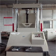
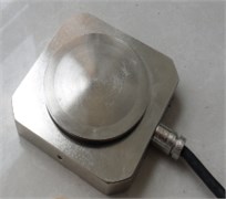
Cycling-trainers are often called cardiopulmonary training equipments. Their original intention is to improve the body’s physique by simulating the outdoor cycling. In order to better approximate the real motion of the outdoor cycling, suspensions are usually installed at the bottom support of cycling-trainers at present. For example, a commercially available cycling-trainer is shown in Fig. 1(a). It mainly includes: the trailer body, the seat, and the bottom suspension. The suspension consists of two spring-damper assemblies. The single spring-damper assembly is shown in Fig. 1(b).
Fig. 1The cycling-trainer equipped with the suspension
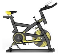
a) A commercially available product
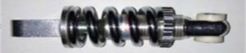
b) The single spring-damper assembly
3. Dynamic modelling of trainer-human coupled system
3.1. Vibration differential equations
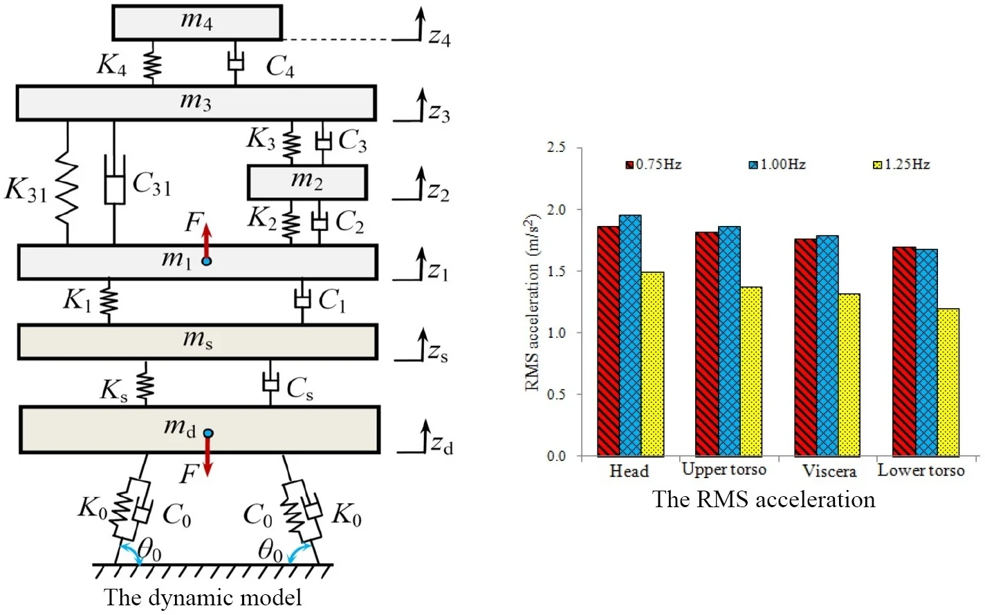
The suspensions of cycling-trainers are mainly used to attenuate the vertical vibration of riders. At present, for the riding comfort, the vertical vibration is mainly evaluated when riding trainers, while the rider horizontal vibration seldom been concentrated. Moreover, the vertical displacement and the vertical vibration acceleration of the human body are often used as the evaluation indexes of the riding comfort [12, 13, 30]. Therefore, this paper mainly focuses on the vertical vibration model of the trainer-human with ignoring the horizontal vibration. In fact, the rotation angle of the trainer body is very small during the cycling process and the length of the trainer body is much larger than its vertical displacement. The human body is mainly in the back of the trainer body. Although the interactional force between cycling-trainer and rider also includes horizontal component, the force has little effect on the vertical vibration [30]. Thus, the motion form of the trainer-human can be taken as the vertical vibration during the cycling process. In addition, when riding this kind of trainer, the rider’s hands are naturally placed on the grip and the back of the rider’s body is almost vertical. Thus, the force acted on the grip by rider is far less than the weight of the arm. In this study, the force was ignored. Basis on the above analysis, this study only considers the vertical biomechanical characteristics of the human body and the vertical motion of the cycling-trainer. Existing biomechanical models of human body can satisfy different analysis purposes, and their degrees of freedom vary greatly [31-33]. The classical 4-DOF (degree-of-freedom) human biomechanical model [34] can better reflect the vertical mechanical characteristics of the human body, so this study adopted the model. Based on the commercially available cycling-trainer with suspension systems in Fig. 1, a non-linear dynamic model of the trainer-human coupled system is established, as shown in Fig. 2.
Fig. 2The dynamic model
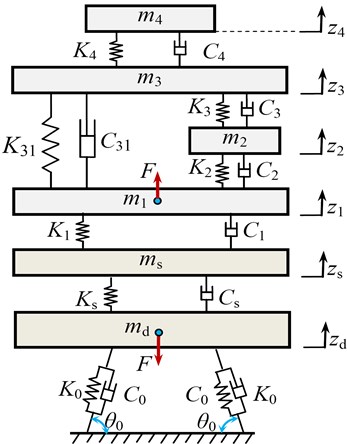
In Fig. 2, , , , and represent the masses of the head, the upper trunk, the viscera, and the lower trunk, respectively. , , , , and are the corresponding stiffness coefficients, respectively. , , , , and are the corresponding damping coefficients, respectively. , , and are the seat mass, the stiffness coefficient and the damping coefficient of the seat suspension. is the installation angle of each spring-damper assembly. and are the stiffness coefficient and the damping coefficient of each spring-damper assembly, respectively. is the effective mass of the trainer body supported by the bottom suspension system, and . Where, is the mass of the trainer body; is the horizontal distance between the bottom suspension and the front support hinge of the trainer body; is the horizontal distance between the mass center and the front support hinge of the trainer body. is the vertical force of the human body. , , , and represent the vertical displacements of the head, the upper trunk, the viscera, and the lower trunk, respectively. and represent the vertical displacements of the seat and the trainer body, respectively.
According to Fig. 2, using Newton’s second law, the differential equation group of the coupled system can be expressed as:
where, and are the equivalent vertical stiffness and the vertical damping of the bottom suspension.
According to the principle of virtual work, and are respectively expressed as:
According to the geometric relation, we can get:
where, is the horizontal distance between the two ends of the single spring-damper assembly in static equilibrium.
3.2. Model parameters acquisition
According to the data sheet provided by the manufacturer, the parameters of the cycling-trainer are shown in Table 1. In the analysis, the parameters of the human model are shown in Table 2 [34].
Table 1The parameters values of the cycling-trainer
Parameter | Value | Parameter | Value |
/ (kg) | 14.0 | /(kN/m) | 18.00 |
/ (kg) | 0.9 | /(Ns/m) | 120 |
/ (°) | 60 | /(kN/m) | 28.8 |
/ (mm) | 25 |
Because the manufacturer did not provide the damping characteristic parameters of the dampers, the two dampers of the two spring-damper assemblies were dismantled in this study. Then, using the test bench, as shown in Fig. 3, the two dampers were tested. For the accuracy of the test results, the two dampers were stored for 6 hours at 20±3℃ before the test. During the test, the displacement excitation signal of the bench was a sinusoidal signal , and 20 mm, 4.2 Hz. The measured velocity-force data are shown in Table 3. According to Table 3, it can be seen that the measured velocity-force data meet the relational expression . Thus, the damping coefficients of the two dampers are approximately equal and both of them are constant 1301 Ns/m. In other words, 1301 Ns/m.
Table 2The parameters values of the human model
Parameter | Value | Parameter | Value |
/ (kg) | 36.0 | / (kN/m) | 10.00 |
/ (kg) | 5.5 | / (kN/m) | 13.44 |
/ (kg) | 15.0 | / (Ns/m) | 2475.0 |
/ (kg) | 4.17 | / (Ns/m) | 330.0 |
/ (kN/m) | 49.34 | / (Ns/m) | 909.1 |
/ (kN/m) | 20.00 | / (Ns/m) | 200.0 |
/ (kN/m) | 19.20 | / (Ns/m) | 250.0 |
Fig. 3The damper test: a) the test bench, b) the master computer
a)
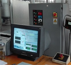
b)
Table 3The measured velocity-force data
Velocity (m/s) | Damping force (N) | |
#1 | #2 | |
–0.52 | –684 | –681 |
–0.39 | –503 | –511 |
–0.26 | –341 | –338 |
–0.13 | –164 | –167 |
0.00 | 2 | –3 |
0.13 | 168 | 161 |
0.26 | 339 | 334 |
0.39 | 509 | 511 |
0.52 | 679 | 686 |
3.3. Alternating excitation
In the process of cycling, the lower limbs of the body are the only power source, and the size and direction of the pedal force change in real time. Under the alternating action of the left foot force and the right foot force, the crank of the cycling-trainer rotates. According to the measured results of the foot force in reference [8], if the vertical position of the crank is taken as the starting point, the vertical component force of one side foot force is approximately half sinusoidal wave when the crank rotates at 0-180°. At this time, the vertical force of the other foot is much less than that of , which can be approximated to zero. When the crank rotates between 180°-360°, the vertical force exerted by the pedal force on both sides is contrary to that applied at 0-180°. In order to facilitate theoretical analysis, the above conclusions can be abbreviated as follows:
where, and are the maximum vertical forces of the left and right foot pedals, respectively, and is the number of the crank rotations, which takes the natural number as its value.
In the actual fitness process, although the force on the left and right sides of the body alternates, the force is basically the same, so it is approximate to . The force can be further expressed as:
where, is the maximum vertical force of , is the frequency, is the riding time.
4. Model validation
To verify the reliability of the dynamic model, a cycling vibration test was conducted. In order to keep in line with the mass parameters of the human body model, a cyclist weighing 61.0 kg was selected. The test site is shown in Fig. 4(a). In order to measure the vertical vibration signal of the lower trunk, a Lance LC0173 acceleration sensor was installed on the seat before the test, as shown in Fig. 4(b). To monitor the vertical pedal force of cyclists, a CHHBC pedal force sensor (TML Inc., Japan) was installed on the pedal, allowing a temperature range of –10 °C~+60 °C, as shown in Fig. 4(d). The data acquisition system is LMS vibration testing system, as shown in Fig. 4(c). By adjusting the rod under the handle of the cycling-trainer, the riding resistance was gradually increased. The tests were carried out separately for three times. Each test lasted 60 seconds and the number of cycles is 60, so the pedal frequency is 1.0 Hz. In addition, based on the parameters in Table 1 and Table 2, the lower trunk acceleration responses were simulated in MATLAB software. The simulation time was set to 60 s. The Runge-Kutta algorithm in MATLAB was adopted and the fixed-step size was set to 0.001 s. The measured data are compared with the simulation values, as shown in Table 4.
Table 4 shows that the measured acceleration values of the lower trunk coincide with the simulation values under the different vertical force amplitudes of 250 N, 300 N, and 350 N, at 1.0 Hz. The maximum deviation is less than 15.0 %, and the RMS (root mean square) deviation is less than 8.0 %. The main reason for the error is that the adopted 4-DOF human biomechanical model cannot fully reflect the human body’s vibration responses. The neglected horizontal force between the cycling-trainer and the rider may be another important reason for the error. In the previous studies [21, 23], when the RMS deviation is less than 10 %, the dynamic models of bikes were deemed acceptable. In the previous study [25], when the maximum deviation of the acceleration is less than about 20 %, a full bicycle dynamic model was deemed acceptable. Refer to their benchmarks, the established dynamic model of the trainer-human coupled system in this study is acceptable. In addition, it can be seen from Table 4 that the greater the vertical force amplitude of the foot is, the greater the vertical vibration acceleration of the human body is.
Table 4A comparison of the lower trunk acceleration values
Amplitude force (N) | Index | The lower trunk acceleration | |||
Test (m/s2) | Simulation (m/s2) | Absolute deviation (m/s2) | Relative deviation (%) | ||
250 | Maximum | 2.18 | 1.87 | 0.31 | 14.2 |
RMS | 1.50 | 1.39 | 0.11 | 7.1 | |
300 | Maximum | 2.48 | 2.24 | 0.24 | 9.8 |
RMS | 1.76 | 1.67 | 0.09 | 5.3 | |
350 | Maximum | 3.04 | 2.62 | 0.42 | 13.9 |
RMS | 2.09 | 1.95 | 0.14 | 6.7 | |
Fig. 4The cycling vibration test
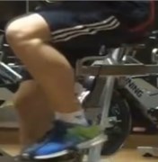
a) The test site

c) LMS vibration testing system
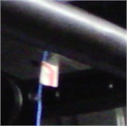
b) The installation of the acceleration sensor
d) The installation of the pedal force sensor
5. Vibration analysis and damping tuning
The dynamic characteristics of the cycling-trainers are mainly reflected in the displacement of the human body. The comfort is reflected in the vibration acceleration of the human body. Therefore, it can be synthetically reflected by the displacement and the acceleration of the human body. In this section, the responses and the influences of the damper damping on the responses are analyzed by solving the dynamic model.
5.1. Vibration responses analysis
Based on the model parameters in Table 1 and Table 2, the vertical biomechanical responses of the human body under the different frequencies, 0.75 Hz, 1.00 Hz and 1.25 Hz for 310 N, were simulated. The vertical displacement response curves of the head, the upper trunk, the viscera, and the lower trunk are similar. The vertical displacement response curves of the lower trunk are shown in Fig. 5(a). The acceleration response curves of the human organs are similar. The vertical acceleration response curves of the lower trunk are shown in Fig. 5(b). The maximum and the RMS values of the vertical responses of the human organs are shown in Fig. 6.
Fig. 5The time histories of the lower trunk vertical vibration
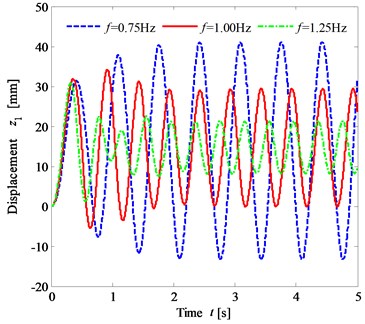
a) The displacement responses
b) The acceleration responses
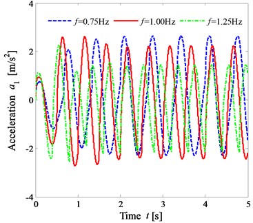
Fig. 6 shows that under the same condition, when the frequency takes three different values, the maximum vertical displacement of the human organ decreases in turn with the increase of the frequency value. When 0.75 Hz and 1.00 Hz, the maximum acceleration and the RMS value are larger, but the difference is not significant. When 1.25 Hz, the maximum acceleration and the RMS value are the smallest. The results show that while riding a cycling-trainer, the greater the vertical force frequency of the foot is, the worse the dynamic sensibility is, but better vibration comfort can be obtained.
Fig. 6The vertical vibration responses of the lower trunk
a) The maximum displacement
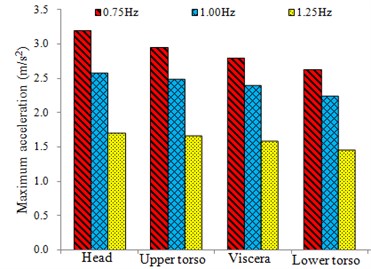
b) The maximum acceleration
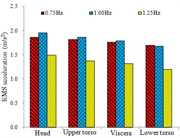
c) The RMS acceleration
5.2. Damping tuning
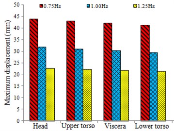
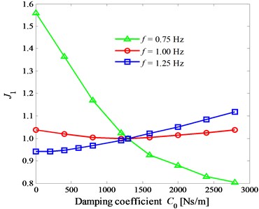
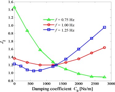
From the above analysis, it can be seen that the vibration responses of the human organs are all approximately sinusoidal in riding the trainer. Therefore, this section takes the vibration responses of the lower trunk as an example to analyze the influences of the damper damping coefficient . In order to analyze the influences of on the maximum displacement , the RMS acceleration , and the maximum acceleration of human lower trunk, the numerical simulations were carried out based on the model parameters. In order to show the variation laws of the curves at the different frequencies on one graph, the vibration responses were normalized. The specific treatment methods are as follows: . Where, the subscript “0” denotes 1300 NS/m. When 0.75 Hz, 1.00 Hz, and 1.25 Hz for 310 N, the response curves of , , and vary with the damper damping coefficient , as shown in Fig. 7(a-c), respectively.
Fig. 7(a) shows that when 0.75 Hz, decreases with the increase of ; when 1.00 Hz, decreases first and then increases with the increase of ; when 1.00 Hz, increases with the increase of . Therefore, the influences of the damper coefficient on the vertical displacement response of the human lower trunk are different under the different riding frequencies. Fig. 7(b) shows that when 0.75 Hz, decreases with the increase of ; when 1.00 Hz, decreases first and then increases with the increase of ; when 1.00 Hz, increases with the increase of . It can be seen that when 1.00 Hz and 1.25 Hz, there exists optimal damping values to minimize the vibration acceleration of the lower trunk, so that the optimal comfort can be obtained. However, when 0.75 Hz, in the range of 0-3000 Ns/m, the greater the damper coefficient is, the better the comfort is. From Fig. 7(c), it can see that the change rule of with is similar to that of with . Thus, in order to improve comfort, the suspension damper can be designed as adjustable. Moreover, under the same pedal force, when the riding speed increases, the suspension damper can be reduced appropriately.
Fig. 7The curves of the index Ji versus the damping coefficient C0 at the different frequencies 0.75 Hz, 1.00 Hz, and 1.25 Hz
a)1
b) 2
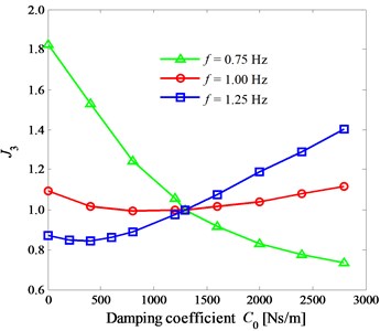
c) 3
6. Conclusions
Aiming at lacking reliable dynamic model of cycling-trainers equipped with suspension systems and lacking the damping tuning method of the suspension damping, the modelling and theoretical analysis were carried out in this paper. The main contributions are as follows: (1) a dynamic model of the trainer-human coupled system was proposed and validated; (2) the influences of the suspension damping on the responses of the coupled system were revealed. Firstly, based on a commercially available cycling-trainer with suspension systems, by using the theory of the human biomechanics, a non-linear dynamic model of trainer-human coupled system was established. Then, by the bench test, the two dampers damping coefficients of the bottom suspension system of the cycling-trainer were measured. Moreover, the dynamic model was validated by riding tests. Moreover, the acceptability of the model was analyzed. Lastly, the influences of the damper damping on the human body were revealed by simulations. The created theoretical model can provide a theoretical tool for analyzing the vertical biomechanical response of the human body during cycling. The revealed laws can provide theoretical basis for the design, optimization, and the damping adjustment of the suspension system for cycling-trainers. In addition, the coupled modelling method and the theoretical analysis method adopted can also provide useful reference for the analysis of the human biomechanical response characteristics in sports and the study of the bicycle competition.
For the following study, the horizontal interactional force between the cycling-trainer and the rider will be considered. The grip will also be focused on. Then, the complex dynamic models will be built.
References
-
Katsigiannis S., Willis R., Ramzan N. A Qoe and simulator sickness evaluation of a smart-exercise-bike virtual reality system via user feedback and physiological signals. IEEE Transactions on Consumer Electronics, Vol. 65, Issue 1, 2019, p. 119-127.
-
Yen C. C. Influence of the seat position of recumbent exercise bikes on riding comfort and fatigue levels of male and female riders. Journal of Technology, Vol. 33, Issue 1, 2018, p. 41-52.
-
Huang S. Y., Yu J. P., Wang Y. K., Liu J. W. Designing an exergaming system for exercise bikes using Kinect sensors and Google earth. Multimedia Tools and Applications, Vol. 76, Issue 10, 2017, p. 12281-12314.
-
Jesus I. R. T., Mello R. G. T., Nadal J. Muscle fatigue assessment during cycle ergometer exercise using principal component analysis of electromyogram power spectra. Journal of Applied Biomechanics, Vol. 32, Issue 6, 2016, p. 593-598.
-
Clarys P., Clijsen R., Barel A. O., Schouteden R., Van Olst B., Aerenhouts D. Estimation of sweat rates during cycling exercise by means of the closed chamber condenser technology. Skin Research and Technology, Vol. 23, Issue 1, 2017, p. 30-35.
-
Mohammadi Abdar H., Ridgel A. L., Discenzo F. M. Test and validation of a smart exercise bike for motor rehabilitation in individuals with parkinson’s disease. IEEE Transactions on Neural Systems and Rehabilitation Engineering, Vol. 24, Issue 11, 2016, p. 1254-1264.
-
Mestre D. R., Maïano Dagonneau C. V. Does virtual reality enhance exercise performance, enjoyment, and dissociation? An exploratory study on a stationary bike apparatus. Presence, Vol. 20, Issue 1, 2011, p. 1-14.
-
Verma R., Hansen E. A., Zee M. D., Madeleine P. Effect of seat positions on discomfort, muscle activation, pressure distribution and pedal force during cycling. Journal of Electromyography and Kinesiology, Vol. 27, 2016, p. 78-86.
-
Tsai M. C., Hu J. S. Implementation of power-aided control for a virtual reality exercise bike. Journal of the Chinese Institute of Engineers, Vol. 30, Issue 5, 2007, p. 923-929.
-
Yen C. C. Exploration of the optimal riding seat position of recumbent exercise bikes. Journal of Chung Cheng Institute of Technology, Vol. 44, Issue 1, 2015, p. 53-67.
-
Chang Shih M. L. C. H., Lin Y. C. Encouraging obese students with intellectual disabilities to engage in pedaling an exercise bike by using an air mouse combined with preferred environmental stimulation. Research in Developmental Disabilities, Vol. 35, Issue 12, 2014, p. 3292-3298.
-
Zhao L. L., Yu Y. W., Zhou C. C., Li X. H. Analytical matching of optimal damping characteristics curve for vehicle passive suspensions. International Journal of Engineering, IJE Transactions C: Aspects, Vol. 31, Issue 12, 2018, p. 2109-2114.
-
Zhou C. C., Zhao L. L., Yu Y. W. Analytical investigation of tire-road contact characteristics for wheelchair robots safely running. International Journal of Engineering, IJE Transactions A: Basics, Vol. 31, Issue 10, 2017, p. 1767-1772.
-
Zhao L. L., Yu Y. W., Zhou C. C. Comparative research on optimal damping matching of seat system for an off-highway dump truck. International Journal of Engineering, IJE Transactions B: Applications, Vol. 31, Issue 2, 2018, p. 204-211.
-
Dow C.-R., Chang S.-M., Bui V.-T., Liu P. A vibration reduction system for e-bikes. 9th Annual Information Technology, Electronics and Mobile Communication Conference, 218, p. 772-775.
-
Kociolek A. M., Lang A. E., Trask C. M., Vasiljev R. M., Milosavljevic S. Exploring head and neck vibration exposure from quad bike use in agriculture. International Journal of Industrial Ergonomics, Vol. 66, 2018, p. 63-69.
-
Munera M., Duc S., Bertucci W., Chiementin X. Physiological and dynamic response to vibration in cycling: a feasibility study. Mechanics and Industry, Vol. 16, Issue 5, 2015, p. 503.
-
Gao J., Sha A., Huang Y. Cycling comfort on asphalt pavement: Influence of the pavement-tyre interface on vibration. Journal of Cleaner Production, Vol. 223, 2019, p. 323-341.
-
Munera M., Chiementin X., Bertucci W. Mechanical equivalent model of vibration transmission in cycling. Computer Methods in Biomechanics and Biomedical Engineering, Vol. 16, 2013, p. 86-87.
-
Waechter M., Riess F., Zacharias N. A multi-body model for the simulation of bicycle suspension systems. Vehicle System Dynamics, Vol. 37, Issue 1, 2002, p. 3-28.
-
Lépine J., Champoux Y., Drouet J.-M. A laboratory excitation technique to test road bike vibration transmission. Experimental Techniques, Vol. 40, Issue 1, 2016, p. 227-234.
-
Lépine J., Champoux Y., Drouet J.-M. Road bike comfort: on the measurement of vibrations induced to cyclist. Sports Engineering, Vol. 17, Issue 2, 2014, p. 113-122.
-
Bu Y., Xiang Z., Huang T. A multi-body model for the simulation of rider and mountain bike coupled system. Proceedings of the World Congress on Intelligent Control and Automation (WCICA), 1669, p. 1672-2008.
-
Bu Y., Xiang Z., Huang T., Zhang X., Wang X. Optimal design and dynamic simulation of mountain bike with rear suspension. Chinese Journal of Mechanical Engineering, Vol. 22, Issue 1, 2009, p. 21-26.
-
He Q., Fan X., Ma D. Full bicycle dynamic model for interactive bicycle simulator. Journal of Computing and Information Science in Engineering, Vol. 5, Issue 4, 2005, p. 373-380.
-
Du W., Zhang D., Zhao X. Research on battery to ride comfort of electric bicycle based on multi-body dynamics theory. Proceedings of the IEEE International Conference on Automation and Logistics, 2009, p. 1722-1726.
-
Ota S., Nishiyama S., Shinohara T. Vibration analysis system for a bicycle with a rider and two infant seats. ASME International Mechanical Engineering Congress and Exposition, 2014.
-
Munera M., Chiementin X., Murer S., Bertucci W. Model of the risk assessment of hand-arm system vibrations in cycling: Case of cobblestone road. Proceedings of the Institution of Mechanical Engineers, Part P: Journal of Sports Engineering and Technology, Vol. 229, Issue 4, 2015, p. 231-238.
-
Chiementin X., Rigaut M., Crequy S., Bolaers F., Bertucci W. Hand-arm vibration in cycling. Journal of Vibration and Control, Vol. 19, Issue 16, 2013, p. 2551-2560.
-
Kan S. C. Analysis of human vertical biomechanical response characteristics in riding exercise bikes. Technology and Innovation, Vol. 24, 2019.
-
Desai R., Guha A. Multibody biomechanical modelling of human body response to direct and cross axis vibration. Procedia Computer Science, Vol. 133, 2018, p. 494-501.
-
Shi L., Liu Z. The three-dimensional biomechanical model building of human lower extremity musculo-skeletal system. Journal of Multiple-Valued Logic and Soft Computing, Vol. 31, Issues 1-2, 2018, p. 23-49.
-
Zhao Y. Kinematics and dynamics analysis of exoskeleton training robot based on the human biomechanical model. International Journal of Mechatronics and Applied Mechanics, Vol. 1, 2017, p. 53-59.
-
Wan Y., Schimmels J. M. A simple model that captures the essential dynamics of a seated human exposed to whole body vibration. Advances in Bioengineering, Vol. 31, 1995, p. 333-334.
Cited by
About this article

This work was supported by the National Natural Science Foundation of China (Grant No. 51575325).
