Abstract
The appearance of self-excited vibrations caused by dry friction of two elements or their contact surfaces is common practice in nature and technique. The braking force that slows down the railway vehicles is associated with dry sliding friction between the brake pads and the wheels. This leads to occurrence of self-excited vibrations in tread brake unit or simply brake block. This paper explores the phenomenon of self-excited vibrations in the brake block of railway vehicles. In order to demonstrate the existence of self-excited vibrations, mathematical model is created in Matlab Simulink and the results are compared with experimental data recorded during braking of electric powered train series 412-416 equipped with tread brake unit. Experimental studies have been performed in laboratory and in real-time conditions with braking train. This paper proves the occurrence of self-excited vibrations, their form and intensity.
1. Introduction
Studies of self-excited (self-induced) vibrations began sometime after World War II. Until today, there are several different theories about the appearance of self-excited vibration. These theories do not exclude each other. Below is a review in chronological order.
Kaidanovsky and Haykin have sought the reason for the appearance of self-excited vibrations in decreasing nonlinear characteristic of the friction force as function of the relative speed of sliding contact surfaces.
Kosterin experimentally investigated self-excited vibrations. He located the cause of their occurrence in the friction contact between sliding surfaces.
The occurrence of self-excited vibrations, was explained by Ishlinski and Kragelski [1, 2] with the difference between static and dynamic friction force Eq. (1):
Le Xuan Anh [3, 4] found out that the current value of the friction force with rapid change of the relative sliding speed does not coincide with the value of the friction force produced in stationary regime, defined by Amontons laws of friction.
It is worth to note the research of the author Pawel Pielc dating from 1992 [5]. He experimentally proved the equation for friction coefficient and friction force.
From recent research, evident are those of the author B. V. Lushnikov [6], which deals mainly with computer modeling of self-excited vibrations. He uses simplified system (Fig. 1) with vibrating mass on a belt conveyor, accompanied with experimental verification test. A similar approach is elaborated in the works of the authors X. J. Meng [7] and J. Shang-shuai et al. [8].
The research presented in this paper refers to several aspects. In the event of self-excited vibrations, sliding between wheel and brake pad occur in both directions of movement-vibration or is greater or less than zero. If this condition is not met, it could result in wheel locking. The relative speed can be zero only in conditions when the time tends to zero.
So far it has been considered that only acts contrary to the direction of rotation of the wheel, but it can also act in the direction of rotation of the wheel depending on the relative speed.
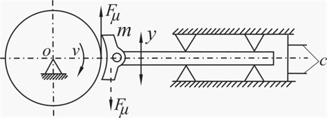
In research of self-excited vibrations regularly the simplified system [9,10] of conveyor type (Fig. 1) is used. In this paper, speed of rotation is reducing because it considers the case of braking.
Fig. 1Conveyor type model with 1-d.o.f.
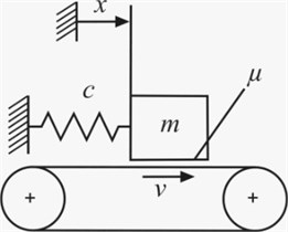
Fig. 2Friction coefficient μ curve
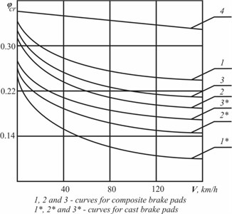
From previous research of self-excited vibrations in dynamic systems it is known that their frequency is high and close to the resonant. Because of the curve (Fig. 2) [11] which describes friction coefficient , and thus the friction force is nonlinear and declining, there is a possibility for occurrence of self-excited vibrations in the brake block when train is braking.
Fig. 3Tread brake unit BCR-6” mechanism
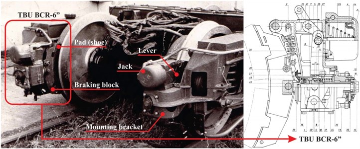
The mechanism of the block is shown on Fig. 3. This type of braking unit is used in combined brakes for fast trains. Regularly they are combined with electromagnetic brakes. Apart from providing a brake force required for braking, they perform automatic regulation of the distance between the wheel and brake pads.
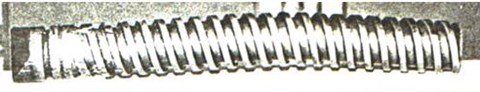
Self-excited vibrations are quite unpleasant for the operation of the brake unit and could lead to collapse or damage of the block in the process of braking (Fig. 4). Thus far, several cases of fallen brake blocks are recorded [12, 13]. This phenomenon initiated the research presented in the paper.
Fig. 4Damaged tread of brake unit
2. Governing equation of the brake block
Based on the real block, for easier theoretical research of self-excited vibrations, dynamic model is defined (Fig. 5).
Fig. 5Dynamic model of the unit
The dynamic model mathematically is represented with non-linear differential Eq. (2):
Excitation emerges from the second member of the equation.
In previous research, friction coefficient between the wheel and brake pad is taken with constant mean value. Therefore, braking force was expressed with Eq. (3):
Based on experimental tests, the friction coefficient between the wheel and brake pad is given with empirical Eq. (4):
The speed at which train starts to brake is 100 km/h. Brake force created by the brake unit is 23 kN (Fig. 6).
Fig. 6Diagram for determining force F0 (*Property of MZT EKA Skopje, Knorr-Bremse Group)
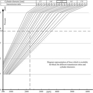
Fig. 7Braking train – real decrease in speed
Therefore, the Eq. (4) takes form Eq. (5):
In this case, the force of friction is function of the relative speed Eq. (7):
The stiffness of the bolt used for fastening the block to the pivot point and its weight is given in Table 1.
Table 1Brake unit parameters
Mass [kg] | Bolt stiffness [N/m] |
100 | 7.2 106 |
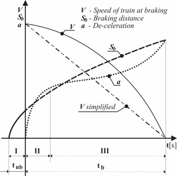
In previous analyzes of self-excited vibrations, the wheel speed was taken to be constant or sine/cosine wave. But, the process of braking is associated with decrease in speed. The braking starts at speed of 100 km/h and lasts 16 s [14] until train speed is zero.
Time of braking (Fig. 7) is obtained by real-time measuring of empty 3-segment electric powered train series 412-416. Train decreasing speed, approximately [15], can be expressed with the following Eq. (10):
The term Eq. (10) is shown on Fig. 7 as simplified. The solid line is a real curve of decreasing braking speed of the train. The approximation for linear decreasing of speed is acceptable because 2/3 [15] of deceleration curve that can be considered to be constant (part III of Fig. 7). Train brakes with constant acceleration.
By substituting Eq. (10) in Eq. (8) the final form of the differential equation is obtained Eq. (11):
3. Differential equation in Matlab Simulink
To solve the Eq. (11), which represents the dynamic model (Fig. 5), block diagram is made in Matlab Simulink.
The approximate equality of the frequency of self-excited vibrations with the resonant frequency of brake block will be used to prove the existence of self-excited vibrations.
3.1. Solution of the differential equation
The solution of differential equation in the process of braking, gives the response in time domain of the brake block. Fig. 8 is a diagram of the acceleration of the brake block caused by train braking from 100 km/h till full stop (16 s). This diagram gives the shape of vibration and is used to find the frequency of self-excited vibrations:
With frequency analysis of the acceleration signal (Fig. 8) the carrying frequency of vibration is obtained (43 Hz). The value is almost identical to resonant frequency of the braking block that can be approximately calculated with Eq. (12).
Fig. 8Brake unit vibrations during train braking
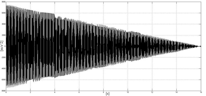
Fig. 9Change of Fμvrel during braking
The change of friction force between the wheel and brake pad is shown in Fig. 9.
It is nonlinear [16]. Also, it is evident that speed of vibration of brake pad is out of phase with the speed of the wheel (there is no adhesion). This confirms the presumption that the relative sliding between the brake pads and the wheels exists in both directions all the time during vibrations of brake pads. Therefore, there is no slip – stick [17, 18] appearance.
4. Experimental investigation
The experiment for investigation of self-excited vibrations of brake unit is carried out in two phases. The first phase is conducted in a laboratory. The second phase is carried out in real-time conditions during train braking. In both cases, the same type of brake block is used (BCR-6”, manufactured in Wabtec MZT Hepos). These brake units are mounted on electric powered train series 412-416 for the second phase.
4.1. Laboratory tests
Fig. 10 shows the apparatus used for laboratory tests and processing of recorded data.
Fig. 10Apparatus used for laboratory test
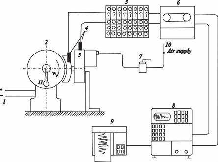
The position (1) and (2) represents the generator-engine with drive shaft attached to the stationary base which plays the role of a real axle assembly. The brake unit (pos. 3) is clamped to a brake pad which is on prescribed distance of 5 mm from the wheel. The brake unit is mounted on a specially made console carrier, rigidly fixed to the base. Pressurized air which supplies the brake cylinder of the unit is controlled with FD1 brake valve (pos. 7).
Two accelerometers HBM B12 (pos. 4) are attached to the brake unit, one on the brake pad and the other on the housing. Accelerometers are connected to 6 channel universal amplifier HMB KWS 6A-5 (pos. 5). Acceleration of the housing and the pad detected during braking are recorded with 4-channel magnetic writer HP3964A (pos. 6) and handled with HP5423A (pos. 8). Processing in time and frequency domain is done with HP5423Aanalyzerand results are printed on a plotter HP7470A (pos. 9). Axle speed is measured and controlled by RPM indicator (pos. 11).
Fig. 11Measured frequency – laboratory conditions
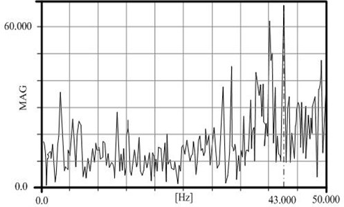
The amplitude-frequency diagram (Fig. 11) is obtained by Fourier transformation of the recorded data during train braking from 100 km/h to zero speed. The dominant frequency of vibration of brake block is 43 Hz. This test in laboratory conditions confirms the accuracy of the mathematical Eq. (11), which defines the dynamic model of the brake unit (Fig. 5).
4.2. Real-time test on braking train
Fig.12 shows the apparatus used for experimental measurement of vibrations under real braking conditions of electric powered train series 412-416 on which brake units are installed.
Fig. 12Apparatus used for real-time test on train
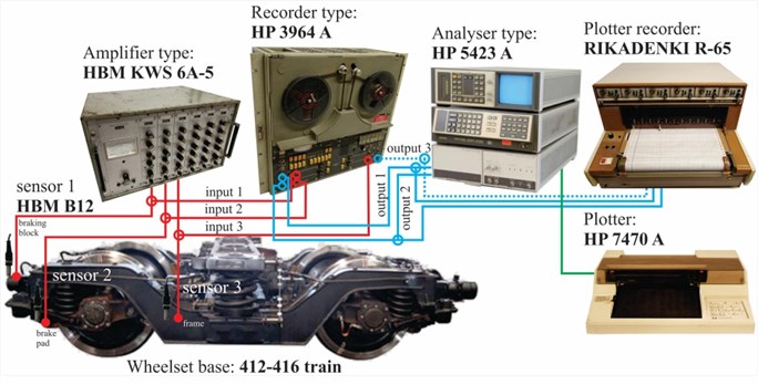
Three accelerometers HBM B12 with measuring range of up to 200 Hz and acceleration of up to 20 g, are connected to 3 separate channels of the HBM KWS 6A-5 universal amplifier as half Wheatstone bridge.
The amplified signal is recorded on 3-channels of magnetic recorder HP3968A and from there distributed to electronic writer RIKADENKI (max. 6 channels). The writings from the last instrument are used for hand graphic analysis of acceleration signals.
The Hewlett-Packard 5423A is a dual-channel, all digital instruments capable of providing time and frequency domain analysis of complex analog signals in the range of dc to 25 kHz. It is used to analyze acceleration signals stored in the magnetic recorder HP3964A.Results obtained from the structural dynamic analyzer HP 5423A are printed with printer HP 7470A.
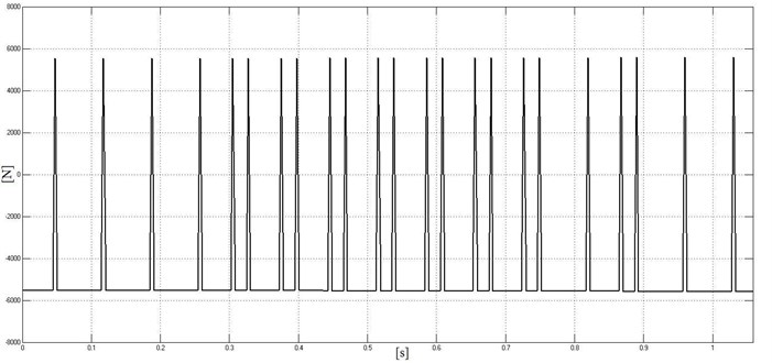
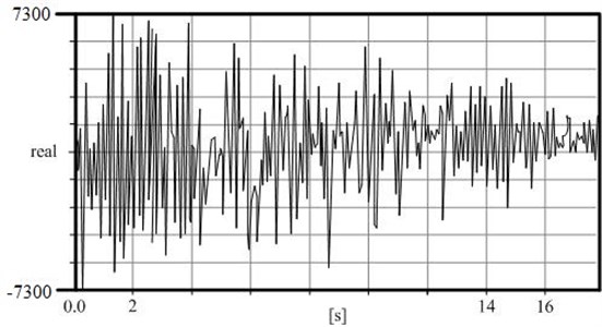
Vibration of the brake unit is given on Fig. 13 for 16 s in time domain during braking process. These forms of vibration have already been obtained with the solution of mathematical Eq. (11) that represents brake block acceleration (Fig. 8).
Fig. 13Recorded vibrations of the break block
Train braking is carried out from a certain speed to complete stop. During these period vibrations are recorded as acceleration data. DAQ is used for complete amplitude-frequency analysis of time domain recordings.
Brake unit vibrations are also recorded in condition when train drives without any braking applied. This procedure is implemented to get comparable values of the frequency of accelerations under free driving and in conditions of braking.
Fig. 14 is amplitude-frequency diagram for a case of a train driving free at speed of 80 km/h. The dominant frequency here is 6.2 Hz. This frequency belongs to the frame which holds the brake unit, while the second frequency disappeared because there is no braking.
Fig. 14A-F diagram for case of free driving train
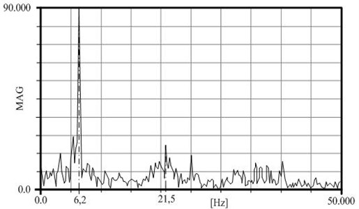
Fig. 15Measured frequency – braking train
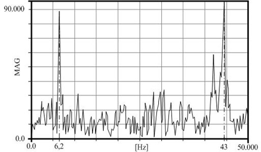
Fig. 15 is an amplitude-frequency diagram of the brake block vibrations recorded during braking from 100 km/h to zero speed. It is clear that two frequencies dominate.
The first frequency is at 6.2 Hz. It’s a result of forced vibrations of train frame caused by contact joints of rail segment, which fully corresponds to the Eq. (13):
This formula [19], approximately calculates the frequency of forced vibrations of the frame (rotary foot to which brake block is attached) caused by the contacts of the rail segments. The parameters of train driving are given in Table 2.
The second frequency is 43 Hz, close to resonant, and is the result of braking under dry friction.
Table 2Parameters of train rail segments
[km/h] | [m] | [-] | [Hz] |
80 | 14.5 | 4 | 6.2 |
5. Conclusions
Based on the conduced theoretical and experimental research, it’s evident that in the process of braking of the train, self-excited vibrations are present all the way down in tread brake unit. Self-excited vibrations are unavoidable when dry friction is present.
The appearance of vibrations exists from the beginning to the end of process of braking.
The frequency of self-excited vibrations is in the range of ±1 around 43 Hz and is approximately equal to the resonant frequency of the braking block.
The nature of vibrations pattern is increasing, stationary and decreasing (Fig. 13).
Dynamic tests of braking units so far have been performed at 25 Hz. The recommendation resulting from the research is that dynamic test of brake units should be performed at range of 43-70 Hz.
In order to avoid the harmful effects of self-excited vibrations and to make the braking process more efficient the following is needed:
– Mounting of brake blocks to the wheelbase frame should to be achieved with screws passing through the block instead of four screws parallel with the main tread (Fig. 3) coming out of the block. Tightening the screws with the prescribed torque (20 Kpm) causes additional axial force which amplifies the influence of vibration and contributes to breaking the bolts and falling of the block;
– For better braking, the self-adjustment mechanism of the brake block should closely regulate the gap between the wheel and the brake pads, automatically in both directions of exploitations (extension and shortening). When brake block has one-directional regulator, de-tuning of the block under the influence of self-excited vibration may appear. Subsequently, the train may not be able to slow down, because the gap would become too large to compensate;
– In order to prevent de-tuning of regulator built-in the brake block, the working and regulating screws inside the block should be manufactured with teeth on the working surfaces;
– The joint (Fig. 3, part 49) between the carrier of brake pads and work spindle should be designed to mitigate the vibrations from the pads of the work spindle, and from there to the block;
– Brake pads should be made of composite materials. The experimental studies have proven that the use of cast brake pads generates self-excited vibration in the brake block with a higher frequency. This is the result of coefficient of friction with highly expressed nonlinearity.
References
-
Ishlinskii A. Y., Sokolov B. N., Chernousko F. L. On the motion of flat bodies with friction, Proceedings of the Academy of Sciences of the USSR, Solid Mechanics, Vol. 4, 1981, p. 17-28, (in Russian).
-
Kragelsky I. V., Gitis N. V. Friction Oscillations. Nauka, 1987, p. 183, (in Russian).
-
Le Xuan Anh On the dynamics of mechanisms with friction. Foundation of Mechanical Engineering, Vol. 4, 1988, p. 62-68.
-
Stamenkovic S., Stojicic S. Analytical determination of the braking distance of railway vehicles using computer. Journal for Railway Transport-Sofia, Vol. 6, 1990, p. 14-17.
-
Pawel Pielc Study of phenomena in wheel-bake shoe contact area. Periodica Polytechnica Transportation Engineering, Vol. 21, Issue 3, 1993, p. 229-238.
-
Lushnikov B. V. Parameter’s vibrodiagnostics of dry uncoloumb friction in self-excited frictional oscillations. Journal of Scientific Review-Technical Sciences, Vol. 1, 2014, p. 238, (in Russian).
-
Meng X. J. Numerical investigation of the influence of friction coefficient on brake groan. Applied Mechanics and Materials, Vols. 44-47, 2010, p. 1923-1927.
-
Shang-shuai J., Qian D. Friction-induced self-excited vibrations and control of a brake system. Journal of Engineering Mechanics, Vol. 29, Issue 3, 2012, p. 252-256.
-
Luo A. C. J., Gegg B. C. Periodic motion in periodically forced oscillator moving on an oscillating belt with dry friction. Journal of Computational and Nonlinear Dynamics, Vol. 1, Issue 3, 2006, p. 212-220.
-
Won H., Chung J. Stick-slip vibration of an oscillator with damping. Journal of Nonlinear Dynamics, Vol. 85, Issue 291, 2016, p. 1-11.
-
Asadcenko V. R. Automatic Brakes of Railway Vehicles. Publishing House Marshrut, Moskva, 2006, p. 57, (in Russian).
-
Garg V. K., Rukkipati R. V. Dynamics of Railway Vehicle Systems. Academic Press, 1994.
-
Iwnicki S. Handbook of Railway Vehicle Dynamic. CRC Press, 2006.
-
IEEE Guide for the Calculation of Braking Distances for Rail Transit Vehicles. IEEE Standard 1698, 2009.
-
Milovanovic M., Lisanin R. Brakes and Braking Railway Vehicles. Faculty of Mechanical Engineering Belgrade, 2000, p. 91, (in Serbian).
-
Kang J., Krousgrill C. M., Sadeghi F. Oscillation pattern of stick-slip vibrations. International Journal of Non-Linear Mechanics, Vol. 44, Issue 7, 2009, p. 820-828.
-
Awrejcewicz J., Olejnik P. Occurrence of stick-slip phenomenon. Journal of Theoretical and Applied Mechanics, Vol. 45, Issue 1, 2007, p. 33-40.
-
Abdo J., Abouelsoud A. A. Analytical approach to estimate amplitude of stick-slip oscillations. Journal of Theoretical and Applied Mechanics, Vol. 49, Issue 4, 2011, p. 971-986.
-
Vershinsky S. V., Danilov V. N., Khusid V. D. Dynamics of Railway Carriages. 3-rd Edition. Publisher Transport, 1991, p. 860, (in Russian).
Cited by
About this article

