Abstract
This paper focuses on the operational modal analysis of the Karun IV dam, the highest concrete arch dam in Iran, based on the responses obtained from ambient vibration tests, which are carried out on the dam during 19 March 2014, and 3 March 2015 earthquake with an epicenter about 133 km northeast of the dam. The non-parametric FDD-Wavelet method is used for identification and extraction of modal parameters including natural frequencies, mode shapes and damping ratios. Nine and four natural frequencies are identified from ambient and seismic responses, respectively. Stabilization diagram and averaged coherence spectrum (ACS) are used to detect and eliminate spurious form true modes. Comparison of the results indicates that identification is performed properly and reliably.
1. Introduction
Performance evaluation of an arch dam during a large earthquake is one of the engineering challenging problems. Dynamic properties of the dam such as, natural frequencies, mode shapes and damping ratios, are the most important factors in the response of the structure to the earthquakes. System identification methods provide these modal characteristics, which are important to achieve the seismic response of dams. The accuracy of the results obtained from seismic analysis depends on having a precise mathematical model that is known as modal model of the system. The most reliable method to achieve the precise mathematical model is calibration of these models by the results obtained from recorded real responses. The real responses can be obtained from the recorded responses during the earthquakes by permanent installed accelerometers on the dam or arranging vibration tests. The mathematical model should be updated so that the precise modal parameters are obtained conforming to the results from the OMA. Therefore, the calibrated mathematical model can be used to evaluate the safety of the existing dams, to predict the response to the destructive earthquakes, to assess the possibility of the damages under extreme loadings and structural health monitoring.
In operational modal analysis, dynamic characteristics of a structure can be extracted using techniques such as peak picking (pp) and Frequency Domain Decomposition (FDD) in the frequency domain [1-4], Stochastic Subspace Identification (SSI) in the time domain [5], and continuous wavelet transform (CWT) in the time – frequency domain [6-7]. The integrated FDD-WT method is introduced in which the wavelet transform is used for decomposition of a signal corresponding to the natural frequencies obtained from the FDD to enhance the estimation of damping ratios [8-10].
In this paper, comprehensive ambient vibration tests are carried out on the dam for six arrangements of sensors on March 19, 2014. The water level was 21 meters below the crest level during ambient vibration tests. On March 3, 2015, Karun IV dam was weakly shaken by the magnitude 1.6 earthquake, which occurred in Isfahan province. The water level during this earthquake was 11 meters lower than the corresponding level to the ambient vibration tests. As the novelty of this research, these two kinds of actual responses of the dam are used for operational modal analysis. The results from ambient vibration tests (weak noises) and seismic responses of the dam (slightly strong noises) are compared and discussed to assure the achieved dynamic properties of the dam.
2. System identification using the FDD-WT method
2.1. Definition
Based on the works of Tarinejad and Damadipour (2014), a non-parametric integrated method under the title of FDD-WT was extended to identify the modal parameters of structures [8-10]. In this method, FDD extracts the values of natural frequencies and mode shapes. In the FDD identification, the first step is estimation of the PSD matrix. The output PSD known at discrete frequencies is then decomposed by taking the SVD of the matrix [4]:
where the matrix is a unitary matrix holding the singular vectors , and is a diagonal matrix holding the scalar singular values . If the power spectral density matrix of the system can be decomposed into its singular values and vectors in the desired frequency, peaks of the first singular value will be equal to the natural frequencies of the system and singular vectors corresponding to the peaks of first singular values approximate the mode shape vectors.
On the other hand, Wavelet transform decouples the measured multicomponent signal to monocomponent signals (i.e. Decouple the signal with several frequency components to single signals with only one frequency component) therefore, it is capable to estimate damping ratios.
2.2. FDD-WT algorithm
After estimating the PSD matrix and decomposition of the power spectral density matrix into its singular values and vectors in the desired frequency [8-10]:
1) Peaks of the first singular value will be equal to the natural frequency of system. Second singular value can be used to estimate the natural frequencies of weak modes that have no peak in first singular value.
2) Singular vectors corresponding to the peaks of the first singular values approximate the system mode shape vectors.
3) Optimum parent wavelet based on minimal Shannon entropy criterion is determined and continuous wavelet transform (CWT) of system responses is calculated. Then, ridges and skeletons of CWT are selected corresponding to the desired frequencies which are extracted in step 1. The algorithm of FDD-WT method is illustrated in Fig. 1.
Fig. 1FDD-Wavelet algorithm [8, 9]
![FDD-Wavelet algorithm [8, 9]](https://static-01.extrica.com/articles/16989/16989-img1.jpg)
3. Case study
Karun IV Dam is a concrete arch dam on the Karun River located at 180 km southwest of Shahre Kord, Iran. The dam height is 230 metres (750 ft) from the foundation and the thickness of the dam varying from 7 meters at the crest to 37-52 meters at the base. The crest is approximately 440 meters in length. The general view of Karun IV Dam is shown in Fig. 2.
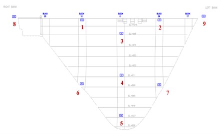
In 2010, an extensive array of tri-axial accelerometers was installed on Karun IV dam. The locations of the 9 accelerometers on the dam and along the abutments are shown in Fig. 3.
These accelerometers were in place on March 3, 2015, when the magnitude 1.6 earthquake occurred with an epicenter about 133 km northeast of the dam and a focal depth of about 10 km. During the earthquake, acceleration responses of the dam were recorded in all channels. The water level was 32 meters below the crest level during the earthquake.
Fig. 2General view of Karun IV dam
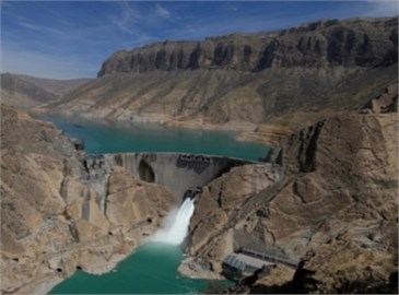
Fig. 3Locations of the 9 accelerometers on the Karun IV dam
4. Ambient vibration tests
Six different arrangements of sensors (A, B, C, D, E and F) during ambient vibration tests on the Karun IV dam are shown in Fig. 4. The velocity responses of the dam were measured in three directions, stream, cross-stream and vertical, using tri-axial seismometers. Structural responses due to ambient vibration recorded in stream direction are selected to identify the modal parameters. The records relating to each arrangement of seismometers is obtained simultaneously in three directions, cross-stream, vertical and stream, with a sampling time interval of 0.005 s. According to the recording schedule presented in Table 1, a total time of approximately 600 s is used for each arrangement except for the case of F that is 300 s.
Fig. 4Location of the sensors for six arrangements A, B, C, D, E and F (downstream view)
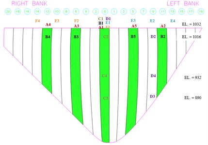
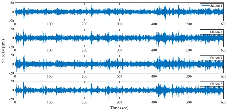
The tests were mainly performed in the crest level and 93 % height of the dam, which is about 16 m below from the crest. Two tests with arrangements C and D were also performed in which the sensors were placed on blocks 0 and 9 (see Fig. 4). Fig. 5 show a sample of time histories recorded at the different stations for north-south direction for arrangement A.
Table 1Recording schedule for six different arrangements
Sensor arrangement | Active stations | Date | Recording time | Used time |
A | 1, 3, 4 and 5 | 2014-03-19 | 07:47 – 07:59 AM | 07:48 – 07:58 AM |
B | 1 to 4 | 11:00 – 11:26 AM | 11:08 – 11:18 AM | |
C | 1 to 4 | 14:01 – 14:31 PM | 14:11 – 14:21 PM | |
D | 1, 3 and 4 | 16:00 – 17:00 PM | 16:25 – 16:35 PM | |
E | 1 | 18:15 – 19:00 PM | 18:30 – 18:40 PM | |
F | 1 and 4 | 19:53 – 20:00 PM | 19:54 – 19:59 PM |
Fig. 5Sample of velocity responses recorded at different stations of arrangement A in stream direction
5. Seismic records of 3 March 2015 earthquake
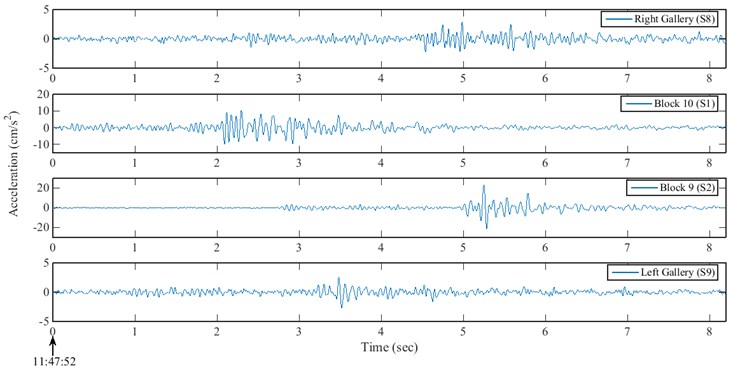
The seismic responses relating to the magnitude 1.6 earthquake of 3 March 2015 were recorded at Karun IV dam by tri-axial accelerometers with a sampling rate of 200 Hz. The stream direction accelerations recorded at the crest level of the dam are presented in Fig. 6.
Fig. 6The recorded responses at the crest level in stream direction
6. Modal identification of Karun IV dam
Considering that the FDD-WT method is based on output-only technique, velocity responses obtained from the stations of six various arrangements A to F are used to review and identify the dynamic characteristics of Karun IV arch dam. Identification process is performed according to the presented algorithm in Fig. 1. In this paper, cyclic averaging technique is used to decrease analysis time and increase of processing precision. The use of cyclic averaging, along with asynchronous or synchronous averaging, is a powerful technique for reducing the leakage, as well as, random errors [12]. Signal processing is performed with 10 cyclic averages. Therefore, for arrangements A to E, averaged signals with time length of 60 s are used instead of them with 600 s and for arrangement F, the signals with time length of 30 s are used to analyze.
Ambient excitation forces can lead to appear spurious peaks in power spectrum of responses. There are some criterions to detect and eliminate spurious modes such as ACS (Averaged Coherence Spectrum) criterion and stabilization diagram. These two criterions are used in this paper.
6.1. Averaged coherence spectrum
The ACS criterion is based on averaging the coherence spectra calculated between different response channels [8, 9]:
In these equations, is the number of response channels, and are the cross power spectral density and the coherence spectrum corresponding to the th and th channels of the recorded response, respectively; and is the Averaged Coherence Spectrum. The ACS intensifies the modal frequencies and plotting it shows a peak around the dominant frequency. Therefore, peaks of the ACS that correspond to the peaks of the first singular value spectrum and which also have their spectral domain near unity, have a strong assurance of corresponding natural frequencies.
6.2. Stabilization diagram
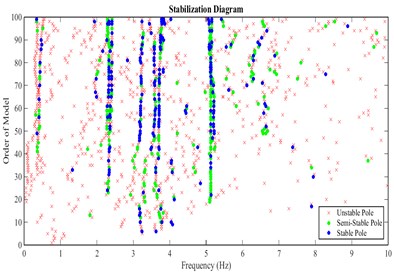
Stabilization diagram is widely used as a robust tool to distinguish the true modes from spurious modes. The technique (stabilization criterion) is based on subspace methods. For stabilization diagram, the stabilization procedure performs system sequentially for all system orders up to a user-specified maximum. At each step, poles identified at the current system order are compared to poles identified at the previous system order. The criteria for defining a pole as stable were chosen as less than 1 % difference in frequency and 5 % difference in damping with a pole identified with the previous model order [13].
Initially, the peaks of singular value spectra are determined in accordance with the stabilization diagram, and then the selected peaks are evaluated using ACS criterion.
7. The results extracted from ambient vibration records
7.1. Natural frequencies
The singular value spectra, stabilization diagram and averaged coherence spectrum of structural responses from different stations for north-south direction, corresponding to arrangements A and B, are shown in Figs. 7-12, respectively. The results of other arrangements are presented in Table 2.
Fig. 7Singular values of the cross power spectral density matrix for the velocities recorded in stations of arrangement A for stream direction
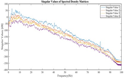
Fig. 8Stabilization diagram obtained from velocities recorded in stations of arrangement A for stream direction
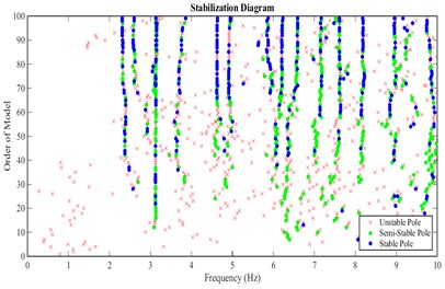
Fig. 9First singular value spectrum and ACS of responses, for arrangement A
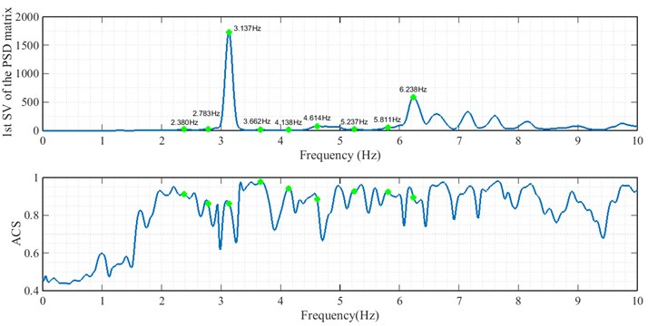
Fig. 10Singular values of the cross power spectral density matrix for the velocities recorded in stations of arrangement B for stream direction
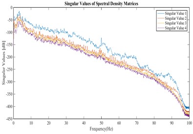
Fig. 11Stabilization Diagram obtained from velocities recorded in stations of arrangement B for stream direction
The frequencies extracted from the first singular value spectrum of the responses are shown for two cases A and B, in Figs. 9 and 12, respectively. Iterative similar frequencies appeared in the results of different arrangements A to F are considered as possible natural frequencies of the arch dam. The frequencies are presented in Table 2.
According to the stabilization diagram and ACS criterion calculated from the records of all arrangements, it can be concluded that the first to fourth modes have a higher certainty. In the following, mode shapes and damping ratios relating to the four modes are presented.
Fig. 12First singular value spectrum and natural frequencies extracted from it, for arrangement B
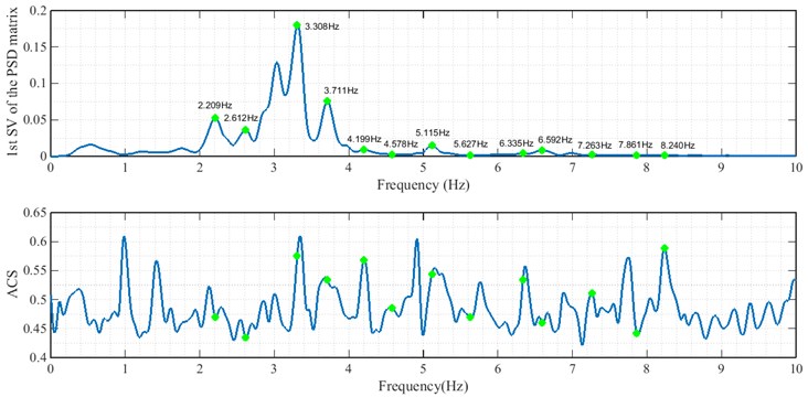
Table 2Natural frequencies of Karun IV dam
Modes | Natural frequencies (Hz) from various arrangements | Mean | |||||
A | B | C | D | E | F | ||
1 | 2.380 | 2.209 | 2.283 | 2.173 | 2.209 | 2.271 | 2.254 |
2 | 2.783 | 2.612 | 2.795 | 2.795 | – | 2.722 | 2.741 |
3 | 3.137 | 3.308 | 3.113 | 3.113 | 3.125 | 3.125 | 3.154 |
4 | 3.662 | 3.711 | 3.669 | 3.735 | 3.748 | 3.735 | 3.710 |
5 | 4.138 | 4.199 | 4.248 | 4.297 | 4.297 | 4.285 | 4.244 |
6 | 4.614 | 4.578 | 4.773 | 4.639 | 4.712 | 4.590 | 4.653 |
7 | 5.237 | 5.115 | 5.127 | 5.115 | 5.127 | 5.151 | 5.145 |
8 | 5.811 | 5.627 | – | 5.737 | 5.823 | 5.676 | 5.735 |
9 | 6.238 | 6.335 | 6.262 | 6.311 | 6.323 | 6.250 | 6.287 |
7.2. Mode shapes
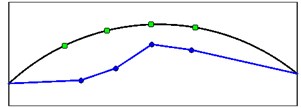
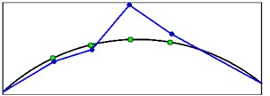
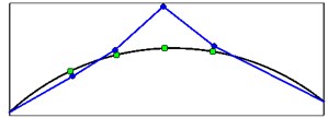
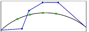
Singular vectors corresponding to the peaks of the first singular value are used to approximate the mode shape vectors. Mode shapes obtained from the crest level responses (arrangement A) are shown in Fig. 13.
Fig. 13Mode shapes from crest level records for four first vibration modes
a) Mode shape 1
b) Mode shape 2
c) Mode shape 3
d) Mode shape 4
It is important to note that mode shapes obtained from OMA methods (output only techniques) are always unscaled. The values of mode shapes relating to the above figure are presented in Table 3.
Table 3The mode shape vectors for four first vibration modes
St. | Mode shapes | |||
1th mode | 2th mode | 3th mode | 4th mode | |
4 | –0.988814 | –0.098406 | –0.135167 | –0.933428 |
3 | –1.000000 | –0.139653 | 0.125273 | 0.362004 |
1 | –0.513071 | 1.000000 | 1.000000 | 0.898133 |
5 | –0.588519 | 0.235745 | 0.131644 | 1.000000 |
7.3. Damping ratios
In the FDD-WT method, damping ratios can be obtained using both the HPB (half-power bandwidth) and the LD (logarithmic decrement) techniques. In this paper, the half-power bandwidth technique (HPB) is applied to single frequency signals (skeletons) obtained from a continuous wavelet transform. Figs. 14 and 15 show the approach of damping estimation using the FDD-WT method for the third mode. It has been calculated based on the crest level responses (arrangement A).
The damping ratios obtained from FDD-WT method are presented in Table 4. The third mode is strong and clear in spectra from all arrangements; therefore, damping results corresponding to the mode is coherent and closely.
Fig. 14CWT of autocorrelation function relating to the crest level responses (arrangement A) and extraction of ridge and skeleton of the third mode
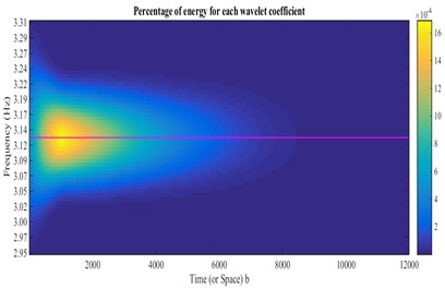
Fig. 15Damping estimation of the third mode using the skeleton extracted from Fig. 14, based on HPBT
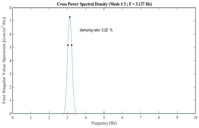
Table 4Damping ratios extracted from HPBT
Arr. | Damping ratios (%) | |||
1th mode | 2th mode | 3th mode | 4th mode | |
A | 4.71 | 3.52 | 3.22 | 2.97 |
B | 4.62 | 4.13 | 3.23 | 2.71 |
C | 5.53 | 3.99 | 3.24 | 3.02 |
D | 5.05 | 4.18 | 3.24 | 2.87 |
E | 5.13 | - | 3.24 | 2.96 |
F | 5.22 | 4.23 | 3.23 | 2.89 |
Mean | 5.04 | 4.01 | 3.23 | 2.90 |
8. The results extracted from seismic records
8.1. Natural frequency
The singular value spectra, stabilization diagram and averaged coherence spectrum of acceleration responses obtained from north-south channels of stations 1 and 2 at crest level (Fig. 3) are shown in Figs. 16-18, respectively.
Fig. 16Singular values of the cross power spectral density matrix obtained from the accelerations recorded in north-south channels of stations 1 and 2 at crest level
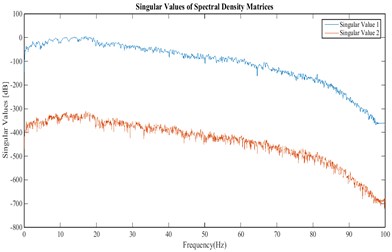
Fig. 17Stabilization diagram obtained from the accelerations recorded in north-south channels of stations 1 and 2 at crest level
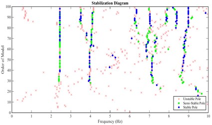
Fig. 18First singular value and averaged coherence spectra obtained from seismic responses recorded at crest level (north-south channels of stations 1 and 2)
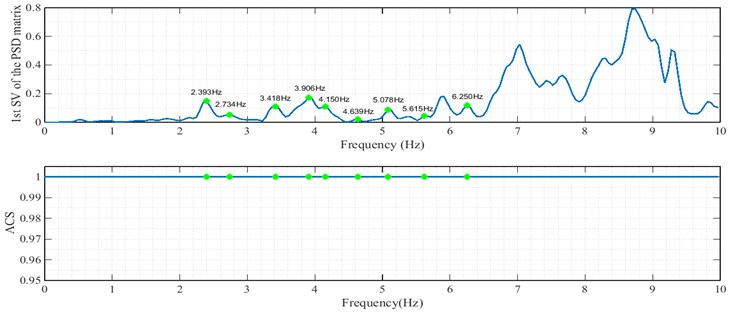
The values of natural frequencies obtained from different channels are presented in Table 5. Comparison of the results indicates that the frequency values obtained from seismic records are similar to the results of ambient vibration test (Table 6).
Comparison of the results relating four first modes is presented in Table 6.
Table 5Natural frequencies obtained from seismic records
Modes | Natural frequencies from the north-south channels of different stations | Mean | |||
1 and 2 (crest) | 1 to 3 | 1 to 4 | 1 to 5 | ||
1 | 2.393 | 2.393 | 2.344 | 2.344 | 2.369 |
2 | 2.734 | 2.734 | 2.734 | 2.734 | 2.734 |
3 | 3.418 | 3.418 | 3.418 | 3.320 | 3.394 |
4 | 3.906 | 3.906 | 3.906 | 3.809 | 3.882 |
5 | 4.150 | 4.150 | 4.150 | 4.199 | 4.162 |
6 | 4.639 | 4.639 | 4.639 | 4.590 | 4.627 |
7 | 5.078 | 5.078 | 5.127 | 5.078 | 5.090 |
8 | 5.615 | 5.615 | 5.615 | 5.566 | 5.603 |
9 | 6.250 | 6.250 | 6.250 | 6.250 | 6.250 |
Table 6Comparison of frequency results obtained from the ambient and seismic records
Modes | Natural frequency (Hz) | |
Ambient vibration test | 3 March 2015 earthquake | |
1 | 2.254 | 2.369 |
2 | 2.741 | 2.734 |
3 | 3.154 | 3.394 |
4 | 3.710 | 3.882 |
8.2. Mode shapes
Mode shapes relating to the peaks of the first singular value obtained from seismic records are shown in Fig. 19. These mode shapes belong to stations 1 and 2 at crest level. Fig. 20 shows comparison of mode shapes obtained from seismic and ambient records for three first modes.
Fig. 19Mode shapes obtained from seismic records for crest level
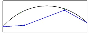
a) Mode shape 1
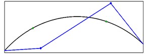
b) Mode shape 2
Fig. 20The comparison of mode shapes obtained from seismic (red) and ambient records (blue)

a) Mode shape 1

b) Mode shape 2

c) Mode shape 3
8.3. Damping ratios
Figs. 21-24 show the damping estimation relating to first and third modes using the FDD-WT method. They have been calculated based on output responses of the crest level.
Fig. 21CWT of autocorrelation function relating to the crest level responses (stations 1 and 2) and extraction of ridge and skeleton of the first mode
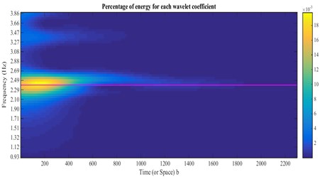
Fig. 22Damping estimation of the first mode using the skeleton extracted from Fig. 23, based on HPBT
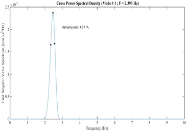
Comparison of damping ratios obtained from ambient and seismic records are indicated in Table 7. The results indicate that the damping ratios obtained from ambient and seismic records have a good agreement.
Fig. 23CWT of autocorrelation function relating to the crest level responses (stations 1 and 2) and extraction of ridge and skeleton of the third mode
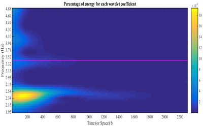
Fig. 24Damping estimation of the third mode using the skeleton extracted from Fig. 25, based on HPBT
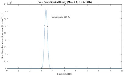
Table 7Comparison of damping results obtained from the ambient and seismic records
Modes | Damping ratios (%) | |
Ambient vibration test | 3 March 2015 earthquake | |
1 | 5.04 | 4.71 |
2 | 4.01 | 4.13 |
3 | 3.23 | 3.05 |
4 | 2.90 | 3.10 |
9. Conclusions
Comprehensive ambient vibration tests on Karun IV arch dam, the highest concrete arch dam in Iran, performed with six different arrangements of sensors. The non-parametric FDD-WT method is used for signal processing of ambient and seismic records. Nine natural frequencies are obtained from ambient vibration tests. Stabilization diagram and ACS criterion are used to detect true modes from spurious modes. Four natural frequencies are obtained from the seismic responses of the dam during 3 March 2015 earthquake. These values have a good consistency with the results obtained from ambient vibration tests. The corresponding mode shapes and damping ratios for consistent modes are obtained and compared. Good agreement was obtained from both ambient and seismic records.
References
-
Tarinejad R., Ahmadi M. T., Harichandran R. S. Full-scale experimental modal analysis of an arch dam: the first experience in Iran. Soil Dynamics and Earthquake Engineering, Vols. 61-61, 2014, p. 188-196.
-
Zhang L., Brincker R., Andersen P. An Overview of operational modal analysis: major development and issues. Proceedings of IOMAC, 2005.
-
Ventura C., Laverick B., Brincker R., Andersen P. Comparison of dynamic characteristics of two instrumented tall buildings. Proceedings of the 21st International Modal Analysis Conference (IMAC), Kissimmee, Florida, 2003.
-
Brincker R., Zhang L., Andersen P. Output-only modal analysis by frequency domain decomposition. Proceedings of the ISMA25 Noise and Vibration Engineering, Leuven, Belgium, 2000.
-
Peeters B., De Roeck G. Reference based stochastic subspace identification in civil engineering. Inverse Problems in Engineering, Vol. 8, 2000, p. 47-74.
-
Daubechies I. Ten Lectures on Wavelets. CBMS-NSF, 1992.
-
Staszewski W. J. Identification of damping in MDOF systems using time-scale decomposition. Journal of Sound and Vibration, Vol. 203, Issue 2, 1997, p. 283-305.
-
Tarinejad R., Damadipour M. Modal identification of structures by a novel approach based on FDD-wavelet method. Journal of Sound and Vibration, Vol. 333, 2014, p. 1024-1045.
-
Tarinejad R., Damadipour M. Operational modal analysis of structures using a new time-frequency domain approach. 6th International Operational Modal Analysis Conference, Spain, 2015.
-
Tarinejad R., Damadipour M. Extended FDD-WT method based on correcting the errors due to non-synchronous sensing of sensors. Mechanical Systems and Signal Processing, Vol. 72, 2016, p. 547-566.
-
Allemang R. J., Phillips A. W. Cyclic averaging for frequency response function estimation. Proceedings of the International Modal Analysis Conference, 1996, p. 415-422.
-
Peeters B., De Roeck G. One-year monitoring of the Z24-Bridge: environmental effects versus damage events. Earthquake Engineering and Structural Dynamics, Vol. 30, Issue 2, 2001, p. 149-171.
Cited by
About this article
The authors would like to thank from Mr. H. Etaati, Deputy of Operation of Iran Water and Power Resources Development Company and manager of Karun4 Dam and Powerhouse Project, and Mr. M. Damadipour for their cooperation and help during this research.
