Abstract
The effects of a rail vibration absorber on suppressing short pitch rail corrugation are studied. Firstly, a rail vibration field test is carried out to analyze the vibration response of the rail with and without the vibration absorbers. Secondly, based on the hypothesis that friction-induced self-excited vibration of a wheel-rail system causes rail corrugation; two finite element models of a wheel-rail system and a wheel-rail-absorber system are established and analyzed. Both sets of rail vibration test results and theoretical results show that the rail absorbers can effectively reduce the friction-induced self-excited vibration of the wheel-rail system in the frequency range of 200-800 Hz, which corresponds to frequencies of short pitch rail corrugation. This may be a main reason that the rail vibration absorber can suppress the formation of short pitch rail corrugation.
1. Introduction
Undulated wear of the top working surfaces of rails is referred to as rail corrugation. Its formation and development cause high levels of vibrations and fast degradation of track and train components. Sometimes serious corrugation of rails leads to a derailment accident. Eliminating or suppressing the formation and development of rail corrugation is an elusive problem in the railway industry. The history of rail corrugation research can be traced back to the early part of the last century. Since then, numerous explanations of this problem have been published [1-3]. The existing theories associated with the generation mechanisms for rail corrugation may be divided grossly into two categories. In the first category, rail corrugation is attributed to a combination of the transient dynamic interaction between the wheel and rail and long term wear. This school of thought is accepted generally [4-8]. In the second category, rail corrugation is due to the instability of the wheelset-track system. The model established based on this school of thought is a self-excited vibration model. Several investigators support the second school of thought [9-12].
On the basis of research of rail corrugation generation mechanisms, many efforts have been made to eliminate the formation and development of rail corrugation. Ilias [13] investigated the influence of rail pad stiffness on vehicle/track interaction and corrugation growth. His study found that stiffer rail pads led to higher corrugation growth. Oyarzabal, et al. [14] developed a method to obtain an optimal solution of the track parameters, which minimized corrugation growth. Christophe et al. [15] studied the effect of rotational vibration absorbers on the mitigation of rail rutting corrugation. Wu [16] investigated the effects of rail absorbers on short pitch rail corrugation growth from the viewpoint of pinned-pinned resonance of the track causing rail corrugation. Eadie, et al. [17, 18] used friction modifiers to control the frictional characteristics of the wheel-rail interface. It was found that bringing the coefficient of friction below a level of about 0.35 might effectively suppress wear-type corrugation.
Although rail corrugation has been studied for a long time, it is still an elusive problem up to date. It has been realized that different types of corrugation arise from different mechanisms, and some types of corrugation can indeed be prevented through proper devices. In recent years, several researchers find that the use of rail vibration absorbers is beneficial in suppressing short pitch rail corrugation [16, 19]. As known, rail vibration absorbers are always used in controlling railway rolling noise. The mechanism of the rail absorber in suppression of short pitch rail corrugation is not clearly known.
In this paper, the effects of a rail vibration absorber on suppressing short pitch rail corrugation are studied from the viewpoint that friction-induced self-excited vibration of a wheel-rail system causes rail corrugation. A rail vibration field test is carried out in Shenzhen metro line 1 to analyze the effects of the rail absorber on dynamic behaviours of the rail. Two finite element models of a wheel-rail system with and without rail absorbers are established and analyzed. In these two models, creep force between the wheel and rail is assumed to become saturated. The simulation and field test results demonstrate that rail vibration absorbers can effectively suppress the unstable self-excited vibration of a wheel-rail system. Therefore, the use of rail vibration absorbers is helpful to prevent or suppress the formation of short pitch rail corrugation. The object of the present work is to extend understanding of the mechanism of rail vibration absorbers in suppression of short pitch rail corrugation.
2. Rail vibration field test
In China, many metro lines experience rail corrugation. Shenzhen metro line 1 was put in service in 2006 and corrugation occurred on the rail heads after a few months. Most recently, rail vibration absorbers were used to prevent the rail corrugation in Shenzhen metro line 1. It is found that the vibration absorbers have a positive effect on prevention and suppression of the formation of short pitch rail corrugation. No new rail corrugation occurs again on the rail head after the rail vibration absorbers were installed in the corrugation section.
In order to have a better understanding of the effects of a rail vibration absorber on suppressing short pitch rail corrugation. A rail vibration test was accomplished at a curved track with a radius of 1100 m in Shenzhen metro line 1. On this curved track, rail corrugations occur on the low rail as shown in Fig. 1. The wavelength of the corrugation is about 50 mm and this is a short pitch rail corrugation. In the measured section, the forward speed of the train is about 70 km/h. Therefore, it could be concluded that the formation frequency of the corrugation is approximately equal to 389 Hz. In order to avoid the rail corrugation-induced vibration, the rail vibration test was carried out after rail grinding.
Fig. 1Short pitch corrugation on low curved rail in Shenzhen metro line 1
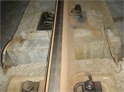
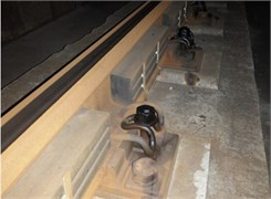
Fig. 2Double-block non-ballasted track with the rail vibration absorbers
2.1. Field test time and measuring instruments
In the field test, the vibration responses of the treated (with absorber) and untreated (without absorber) tracks were measured respectively. The vibration test of the untreated track was carried out on a weekday morning before the installation of rail vibration absorbers. The test time was between 7:30 am and 11:00 am. During this time period, the interval between passing trains running through the measured section was about 4 minutes. A total of 34 sets of vibration acceleration data were recorded. After four days, the rail vibration absorbers were installed on the rail web in the measured section. Fig. 2 shows the double-block non-ballasted track with rail vibration absorbers. A single rail absorber is a steel mass block (10 kg) installed on the rail web by glue and clips. The vibration responses of the treated track were measured on the same railway section and in the same daily time period as the untreated track. The running time and the types of the trains are almost the same as four days before. The total number of the vibration acceleration records of the treated track is also 34. The vibration acceleration records of the treated and untreated tracks were grouped by the start time of the test. Every group of vibration acceleration records have similar test start time. For example, a vibration test of the untreated track was started at 9:05 am. After four days, another vibration test of the treated track was started at 9:06 am. These two vibration acceleration records constitute a record group.
In the testing process, the vibration response of the rail was measured by the accelerometers. They were mounted vertically and laterally at the rail bottom as shown in Fig. 3(a). Measurement points were located at the mid-span between two sleepers as shown in Fig. 3(b). Each of the accelerometers connects with a charge amplifier, which could measure an acceleration signal of 0-1000 g at a frequency of 1-15000 Hz.
Fig. 3Installation of the accelerometers
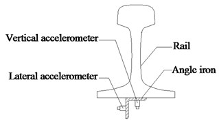
a) Installation diagram of the vertical and lateral accelerometers
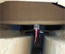
b) Location of the accelerometers
2.2. Rail vibration filed test results
As known, the vertical vibrations of the rail have a significant effect on rail corrugation. Therefore, the analysis of the rail vibrations is focused on the vertical vibrations. Fig. 4 shows a group of vertical vibration accelerations of the treated track and the untreated track. It can be observed that the amplitude of the vertical vibration acceleration decreased when the rail absorbers were installed. In order to better describe the effect of the rail absorber on suppressing the vibration of the rail, the root mean square (RMS) values of the oscillation amplitude of the vertical vibration data were calculated. In the calculation process, the sampling rate of the vibration acceleration is 4000 Hz, the time length of the vibration acceleration record is 20 seconds. The RMS values of the vertical vibration data shown in Fig. 4 are 48.2 m/s2 (without absorber) and 30.9 m/s2 (with absorber). There are a total of 34 groups of vertical vibration acceleration data recorded (with and without absorber). The RMS values of these vertical vibration acceleration records are shown in Fig. 5. It can be found that in most cases, the vibration intensity (RMS values) of the rail decreased when the rail absorbers were installed.
Fig. 4Vertical vibration accelerations of the rail
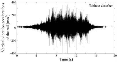
a) Without rail vibration absorber
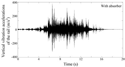
b) With rail vibration absorber
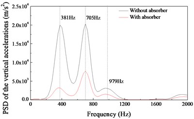
Fig. 6 shows the power spectral density (PSD) analysis results of the field test data. When the rail vibration absorbers are not installed, the vertical vibration accelerations of the rail are always characterized by three main frequencies: about 381 Hz, 705 Hz and 979 Hz. When the rail vibration absorbers are installed, the vertical vibration of the rail at the frequency of 381 Hz has been significantly suppressed. It is worth noting that the vibration frequency of 381 Hz is very near the formation frequency of the short pith corrugation in the measured section (about 389 Hz). This is the main reason that the rail vibration absorber can suppress the short pitch rail corrugation in the measured section. After the rail vibration absorbers were installed, no rail corrugation occurs again on the rail head in the measured section.
Fig. 5The RMS values of the vertical vibration acceleration records of the rail
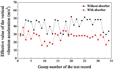
Fig. 6PSD analysis of the vertical accelerations
3. Numerical simulation studies
3.1. Model of a wheel-rail-absorber system
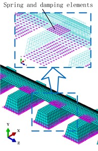
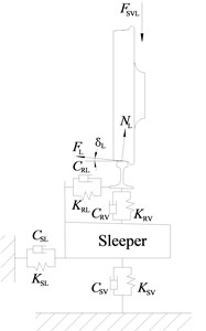
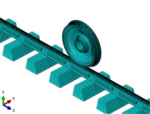
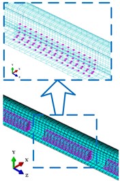
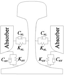
In order to further analyze the mechanism of the rail absorber in suppressing short pitch rail corrugation. Based on the structure parameters of Shenzhen metro line 1, a wheel-rail finite element model is established. It includes a wheel, a rail and a series of sleepers (Fig. 7(a)). In this model, every sleeper is supported by a group of grounded springs and dampers. The number of spring or damper elements in each group is the same as the node number of the sleeper bottom. The contact nodes between the rail and sleepers have the identical coordinates. These contact nodes are connected by the spring and damping elements in lateral and vertical directions (Fig. 7(b)). The effective values of these spring and damping elements are equal to the connection stiffnesses and damping values of the rail fasteners. The contact point between the wheel and rail is at the vicinity of the center of rail head for rail and the middle position of the tread for wheel. Fig. 7(c) shows the contact schematic of the wheel-rail system. In the field test process, the authors find that when a train travels on the measured section, the magnitude of the traction force is always at a large value. In this case, the creep force between the wheel and rail is also at a large value (approaches or reaches the saturated state). Therefore, in this finite element model, it is assumed that the creep force between wheel and rail is always saturated. The saturated creep force is similar to the friction force (equal to the normal contact force multiplied by the dynamic friction coefficient). On the basis of the wheel-rail finite element model, a wheel-rail-absorber finite element model is established as shown in Fig. 8(a). In the wheel-rail-absorber finite element model, the dimensions of the rail absorber model are the same as the rail absorber used in Shenzhen metro line 1. The mass of the rail absorber model is set to 10 kg. The rail vibration absorber models are attached to each side of the rail web by spring and damping elements. The contact nodes between the rail and absorbers also have the identical coordinates. The distributions of springs and dampers between the rail and absorbers are shown in Fig. 8(b). The contact schematic of the rail and absorbers is shown in Fig. 8(c). In these models, the suspension force of the carriage () is considered a static load to the wheel, the influence of the vehicle vibration is not taken into account. The contact surface of the rail is considered perfectly smooth. Under these conditions, the self-excited vibration of the wheel-rail system may arise. The modelling parameters of the wheel-rail-absorber system are listed in Table 1. The contact parameters (contact angle, suspension force) are calculated by the NUCARS simulation software (vehicle forward speed 70 km/h). The structure parameters (dimensions of the wheel and rail, spacing of sleeper) are the actual measured data of Shenzhen metro line 1. The connection parameters (connection stiffness and damping between rail and sleepers, etc.) are identified from experiment data of the double-block non-ballasted track [20]. In this model, the wheel, rail, sleepers and absorbers are modelled by the 8-node hexahedron elements. The vibration monitoring points are on the bottom of the rail, which is the same as in the rail vibration filed test.
Fig. 7Model of a wheel-rail system: a) finite element model of the wheel-rail system; b) distribution of spring and damping elements between the rail and sleepers; c) contact schematic of the wheel-rail system

a)
b)
c)
Fig. 8Model of a wheel-rail-absorber system: a) finite element model of a wheel-rail-absorber system; b) distribution of springs and dampers between the rail and absorbers c) contact schematic of the rail and absorbers
a)
b)
c)
3.2. Transient dynamic analysis
In this paper, Abaqus/Standard solver is used to simulate the dynamic behaviour of the wheel-rail system in the time domain. In the simulation process, the friction forces between the wheel and rail are calculated by Coulomb’s friction law. The friction stresses can be expressed in the form [21]:
where is the friction coefficient, is the contact pressure; is the equivalent slip rate; (1, 2) is the normalized slip direction in the contact plane.
The linearized expression of the Eq. (1) is:
The first term in Eq. (2) yields the asymmetric contribution () to the stiffness matrix. This term can lead to the friction coupling phenomenon between the wheel and rail. The second and third terms of Eq. (2) contribute to the damping matrix.
The implicit time integration is used to calculate the dynamic behaviour of the wheel-rail system. In the calculation process, the equation of motion of the wheel-rail system is [22]:
where is the consistent mass matrix, is the internal force vector, which contains the effects of friction coupling between the wheel and rail, is the applied load vector.
Substitution of the implicit integration operator in Eq. (3) yields:
Eq. (4) is integrated using the Newmark scheme. The displacement and velocity vectors of the wheel-rail system are given in the following equations:
With:
The maximum increment of is set to 0.00005 s (equivalent to 20000 Hz). This integration frequency is much higher than the maximum formation frequency (about 900 Hz) of short pitch rail corrugation. Two analysis steps are required to simulate the dynamic behaviour of the wheel-rail-absorber system. Firstly, a nonlinear static analysis step is used to apply the suspension force on the wheel. Secondly, the nonlinear implicit integration is applied to calculate the dynamic response.
3.3. Simulation results and discussion
3.3.1. Effect of the rail vibration absorbers
In this section, the dynamic simulation results are presented. Fig. 9 shows the dynamic behaviour of the wheel-rail system when the effect of friction coupling between the wheel and rail is considered. In the analysis procedure, the velocities of the wheel are set to 70 km/h (translational) and 46.29 rad/s (rotational). The friction coefficient between the wheel and rail is set to 0.45. Fig. 9(a) shows the vertical vibration accelerations of the rail with and without absorbers. It can be observed that the oscillation amplitude of vertical vibration of the rail decreases significantly when the rail vibration absorbers are installed on the rail web. This phenomenon is consistent with the field test results (Fig. 4). The decrease in amplitude of the simulation results is greater than that of the field test results. This is because the influence of the vehicle vibration is not considered on the wheel-rail system in the simulation process. As known, the contact force between the wheel and rail is difficult to measure in the field test. However, it can be calculated easily in the finite element analysis process. The variations of normal contact forces between the wheel and the rail are shown in Fig. 9(b). The normal contact force is the total force in the direction perpendicular to the contact surface as a result of the contact pressure. It is found that variation in amplitude of normal contact force also decreases when the rail vibration absorbers are installed. The decrease of variation amplitude of normal contact force is helpful to prevent or suppress the formation of rail corrugation.
Table 1Parameters of materials and structure of the wheel-rail-absorber model
Material parameters | ||||
Young’s module (GPa) | Density (kg/m3) | Poisson’s ratio | ||
Rail and wheel | 210 | 7800 | 0.3 | |
Sleepers | 32.5 | 2400 | 0.3 | |
Absorbers | 190 | 7850 | 0.29 | |
Structure and connection parameters | ||||
Suspension force | 91,800 N | |||
Contact angle | 4.26° | |||
Length of the rail | 46 m (60 kg/m) | |||
Nominal diameter of the wheel | 840 mm | |||
Spacing of sleeper | 600 mm | |||
Stiffnesses of the rail fasteners | 4.1×10⁷ N/m, 8.9×10⁶ N/m | |||
Damping values of the rail fasteners | 9.8×10³ Ns/m, 2.1×10³ Ns/m | |||
Connection stiffnesses of the absorbers | 5.0×10⁷ N/m, 2.5×10⁷ N/m | |||
Connection damping values of the absorbers | 4.0×10⁴ Ns/m, 2.0×10⁴ Ns/m | |||
Support stiffnesses of the sleeper and roadbed | 8.9×10⁷ N/m, 5.0×10⁷ N/m | |||
Support damping values of the sleeper and roadbed | 8.9×10⁴ Ns/m, 4.0×10⁴ Ns/m | |||
Fig. 9Dynamic behaviour of the wheel-rail system in the time domain
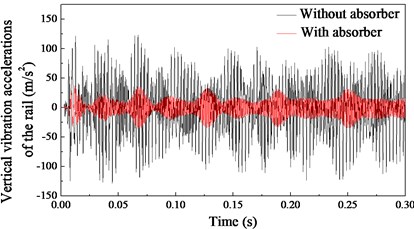
a) Vertical vibration accelerations of the rail
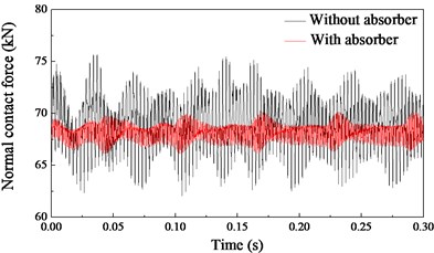
b) Variations of the normal contact forces
The vibration frequency of the rail and wheel is a very important factor in the formation process of rail corrugation. Fig. 10 shows the PSD analysis results of the simulation data. It can be found that the vibrations of the rail are characterised by three main frequencies (352.7 Hz, 688.4 Hz and 1008.3 Hz) when the rail vibration absorbers are not installed (Fig. 10(a)). These main vibration frequencies are very close to the field test results (381 Hz, 705 Hz and 979 Hz in Fig. 6). When the rail vibration absorbers are installed on the rail web, the vibrations of the rail are characterised by one main frequency of 982.6 Hz, the vibrations at the frequency of 352.7 Hz and 688.4 Hz have been suppressed as shown in Fig. 10(a). Fig. 10(b) shows the PSD analysis results of the normal contact forces. The fluctuation frequencies of the normal contact forces are 32.4 Hz, 352.7 Hz, 688.4 Hz and 1008.3 Hz when the rail absorbers are not installed. The fluctuation frequency of 32.4 Hz is induced by the discrete support of the sleepers (70 km/h = 19444.4 mm/s, 19444.4 mm/s÷600mm = 32.4Hz). The main fluctuation frequency of the normal contact forces is 352.7 Hz. This frequency is very close to the formation frequency of the short pith corrugation in the measured section (389 Hz). Fig. 10(b) also shows that the fluctuation of the normal contact force at 352.7 Hz and 688.4 Hz can be suppressed by means of the rail vibration absorbers.
Fig. 10PSD analysis results
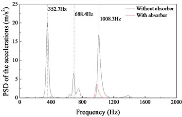
a) PSD analysis results of the vertical vibration accelerations shown in Fig. 9(a)
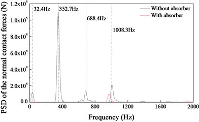
b) PSD analysis results of the normal contact forces shown in Fig. 9(b)
3.3.2. Mechanism of the rail vibration absorber in suppressing rail corrugation
In the previous section, the comparisons among the field test data and the numerical simulation results show that they have good agreement. It is worth noting that the external excitation is not considered in the simulation process. The wheel-rail model exhibits friction-induced self-excited vibration. Therefore, it can be deduced form the simulation and field test results that the major vibration of the rail is the friction-induced self-excited vibration when a train passes through the measured section in Shenzhen metro line 1. In addition, the dynamic simulation results indicate that the self-excited vibration between the wheel and rail can induce the fluctuation of the normal contact force. When the rail absorbers are not installed, the main vibration frequencies of the normal contact force are very close to the formation frequencies of the short pitch rail corrugation.
The conclusion that oscillation of frictional power between the wheel and rail results in rail corrugation is generally accepted by the railway research community [23, 24]. When the self-excited vibrations occur on the wheel-rail system, a simplified wear equation of the rail can be written as [25]:
where is wear volume over the track distance, is the wear rate and is set to constant, is the durability frictional power, is the frictional power and is related to the normal contact force :
where is the creep force, and in the simulation process, is equal to the friction force; is the relative velocity; is the friction coefficient; is the normal contact force.
In the calculation process, and are set to constant. Accordingly, the friction work rate and the wear volume over the track distance fluctuates at the same frequency as the normal contact force . The fluctuation of wear volume can lead to the formation of rail corrugation. Therefore, suppressing the fluctuation of the normal contact force is helpful to eliminate or suppress the formation of rail corrugation.
In the field of rail corrugation research, it is generally accepted that the wavelengths of short pitch rail corrugation are restricted to the range between 20 and 85 mm [3]. When the forward speed of the train 70 km/h, the corresponding formation frequencies of the short pitch rail corrugation are between 228 Hz to 972 Hz. The transient dynamic analysis results (Fig. 10) indicate that the rail vibration absorber can obviously restrain the self-excited vibration of the wheel-rail system and the fluctuation of the normal contact force in the frequency range of 200-800 Hz ( 70 km/h). This range falls in the frequency range of short pitch rail corrugation. Therefore, it can be concluded that the use of rail vibration absorber is helpful to prevent or suppress the formation of short pitch rail corrugation.
3.3.3. The instability propensity of a wheel-rail system due to the friction coupling
In this section, the stability of the wheel-rail system in the frequency domain is studied by using the complex eigenvalue analysis method. Fig. 11 shows the effective damping ratios of the wheel-rail system with and without the rail absorbers. In the complex eigenvalue analysis results, the smaller the effective damping ratio, the easier for the corresponding vibration to occur. It can be found that the vibration frequencies of the wheel-rail system are 363.9 Hz (without the absorber) and 335.7 Hz (with the absorber). These frequencies are close to the formation frequency (about 389 Hz) of the short pith corrugation in Shenzhen metro line 1. This simulation result further suggests that the self-excited vibration of the wheel-rail system causes short pitch rail corrugation in the measured section. Furthermore, the effective damping ratio of the untreated rail ( –0.0059) is smaller than that of the treated rail ( –0.0042). This shows that the unstable self-excited vibration of the wheel-rail system occurs more easily when the absorbers are not installed. Fig. 12(a) shows the unstable mode shape of the wheel-rail system when the absorbers are not installed. It is seen that this is the 1st nodal diameter mode of the wheel and the nodal diameter is along the axis. When the rail vibration absorbers are installed on the rail web, the unstable vibration still take place on the wheel, and the nodal diameter is along the axis as shown in Fig. 12(b). The complex eigenvalue analysis results demonstrate that the probability of the unstable self-excited vibration occurrence of a wheel-rail system can be effectively reduced by means of the rail vibration absorbers. The vibration mode of the wheel-rail system has changed slightly when the rail vibration absorbers are installed.
Fig. 11Distribution of the effective damping ratios. without absorber (●): unstable frequency fR= 363.9 Hz, effective damping ratio ζ= –0.0059; with absorber (▲): fR= 335.7 Hz, ζ= –0.0042
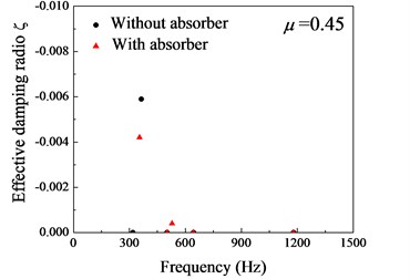
Fig. 12Unstable mode shape of the wheel-rail system
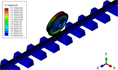
a) without absorber, 363.9 Hz, –0.0059
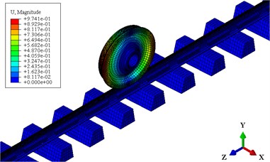
b) with absorber: 335.7 Hz, –0.0042
3.3.4. Effect of the friction coefficient on self-excited vibration
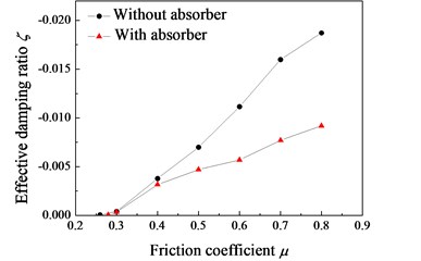
Fig. 13 shows evolution of the effective damping ratio at different values of friction coefficient when the unstable frequencies are 335 Hz (with the absorber) and 363 Hz (without the absorber). It can be found that the effective damping ratio of the untreated rail is always smaller than that of the treated rail. This phenomenon indicates that the propensity of the unstable vibration of the wheel-rail system decreases when the rail absorbers are installed. From Fig. 13, it can be observed that the unstable vibration occurs when the friction coefficient 0.26 (without absorber) and 0.28 (with absorber). And when the friction coefficient is less than 0.4, the effect of rail vibration absorber is relatively small.
Fig. 13Evolution of the effective damping ratio with different friction coefficient μ, with absorber: fR= 335 Hz; without absorber: fR= 363 Hz
3.3.5. Effects of the connection stiffness and damping of the rail vibration absorber on self-excited vibration of a wheel-rail system
In the wheel-rail-absorber model, the lateral connection stiffness is equal to half of the vertical connection stiffness . Fig. 14(a) shows the variation of the effective damping ratio at several different levels of connection stiffness. It is found that with the increase of connection stiffness between the absorber and the rail web, the absolute value of the negative effective damping ratio decreases. This result suggests that increasing the connection stiffness of rail vibration absorber can reduce the propensity of self-excited vibrations of the wheel-rail system. Larger connection stiffness between the absorber and the rail web is beneficial for suppressing the rail corrugation.
Fig. 14Variation of the effective damping ratio ζ with different connection stiffness and damping between the absorber and rail web
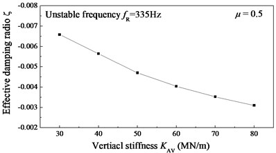
a) Connection stiffness, 4.0×10⁴ Ns/m and 2.0×10⁴ Ns/m
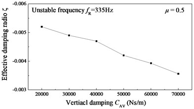
b) Connection damping, 5.0×10⁷ N/m and 2.5×10⁷ N/m
Fig. 14(b) shows the variation of the effective damping ratio with connection damping between the rail vibration absorber and the rail web (×2). It can be observed that with the increase of connection damping of the rail vibration absorber, the absolute value of the negative effective damping ratio decreases. This simulation result demonstrates that the probability of the rail corrugation occurrence reduces with an increase in the connection damping of the rail vibration absorber.
4. Conclusions
The present work studies the effect of rail vibration absorber on short pitch rail corrugation. A field test was carried out in Shenzhen metro line 1 to analyze the vibration response of the rail with and without the vibration absorber. Two finite element models of a wheel-rail system and a wheel-rail-absorber system are established and analyzed. The following conclusions can be drawn.
1) The rail vibration absorber can effectively restrain the friction-induced self-excited vibration of a wheel-rail system in the frequency range of 200-800 Hz. These frequencies fall in the frequency range of short pitch rail corrugation. This is a main reason that the rail vibration absorber can suppress the formation of short pitch rail corrugation.
2) The probability of the unstable self-excited vibration occurrence of a wheel-rail system can be effectively reduced by means of the rail vibration absorbers when the friction coefficient between the wheel and rail is above 0.4.
3) The connection stiffness and damping between the vibration absorber and the rail web have a significant effect on self-excited vibration of a wheel-rail system. Increasing the connection stiffness and damping of the rail vibration absorber is beneficial for suppressing the short pitch rail corrugation.
References
-
Grassie S. L., Kalousek J. Rail corrugation: characteristics, causes and treatments. Journal of Rail and Rapid Transit, Vol. 223, 2009, p. 581-596.
-
Oostermeijer K. H. Review on short pitch rail corrugation studies. Wear, Vol. 265, 2008, p. 1231-1237.
-
Sato Y., Matsumoto A., Knothe K. Review on rail corrugation studies. Wear, Vol. 253, 2002, p. 130-139.
-
Hempelmann K., Knothe K. An extended linear model for the prediction of short pitch corrugation. Wear, Vol. 191, 1996, p. 161-169.
-
Matsumoto A., Sato Y., et al. Study on the formation mechanism of rail corrugation on curved track. Vehicle System Dynamics, Vol. 25, 1996, p. 450-465.
-
Xie G., Iwnicki S. D. Calculation of wear on a corrugated rail using a three-dimensional contact model. Wear, Vol. 265, 2008, p. 1238-1248.
-
Jin X. S., Wen Z. F., Wang K. Y., Zhang W. H. Effect of a scratch on curved rail on initiation and evolution of rail corrugation. Tribology International, Vol. 37, Issue 5, 2004, p. 385-394.
-
Zhao X., Li Z., Liu J. Wheel-rail impact and the dynamic forces at discrete supports of rails in the presence of singular rail surface defects. Journal of Rail and Rapid Transit, Vol. 226, 2012, p. 124-139.
-
Clark R. A., Scott G. A., Poole W. Short wave corrugation-an explanation based on stick-slip vibrations. Applied Mechanics Rail Transportation Symposium, ASME, 1988, p. 141-148.
-
Ishida M., Moto T., Takikawa M. The effect of lateral creepage force on rail corrugation on low rail at sharp curves. Wear, Vol. 253, 2002, p. 172-177.
-
Sun Y. Q., Simson S. Wagon-track modeling and parametric study on rail corrugation initiation due to wheel stick-slip process on curved track. Wear, Vol. 265, 2008, p. 1193-1201.
-
Kurzeck B. Combined friction induced oscillations of wheelset and track during the curving of metros and their influence on corrugation. Wear, Vol. 271, 2011, p. 299-310.
-
Ilias H. The influence of rail pad stiffness on wheelset/track interaction and corrugation growth. Journal of Sound and Vibration, Vol. 227, Issue 5, 1999, p. 935-948.
-
Oyarzabal O., Gomez J., Santamaria J., et. al. Dynamic optimization of track components to minimize rail corrugation. Journal of Sound and Vibration, Vol. 319, Issues 3-5, 2009, p. 904-917.
-
Collette C., Horodinca M., Preumont A. Rotational vibration absorber for the mitigation of rail rutting corrugation. Vehicle System Dynamics, Vol. 47, Issue 6, 2009, p. 641-659.
-
Wu T.X. Effects on short pitch rail corrugation growth of a rail vibration absorber/damper. Wear, Vol. 271, 2011, p. 339-348.
-
Eadie D. T., Santoro M., Oldknow K., Oka Y. Field studies of the effect of friction modifiers on short pitch corrugation generation in curves. Wear, Vol. 265, 2008, p. 1212-1221.
-
Eadie D. T., Santoro M. Top-of-rail friction control for curve noise mitigation and corrugation rate reduction. Journal of Sound and Vibration, Vol. 293, Issues 3-5, 2006, p. 747-757.
-
Croft B. E., Jones C. J. C., Thompson D. J. Reducing wheel-rail interaction forces and roughness growth by application of rail dampers. Noise and Vibration Mitigation for Rail Transportation Systems, Springer, Berlin, 2008, p. 392-398.
-
Li Xia Study on the Mechanism of Rail Corrugation on Subway Track. Ph.D. Dissertation, Southwest Jiaotong University, 2012.
-
Oden J. T., Pires E. B. Nonlocal and nonlinear friction laws and variational principles for contact problems in elasticity. Journal of Applied Mechanics, Vol. 50, 1983, p. 67-73.
-
Hilber H. M., Hughes T. J. R., Taylor R. L. Improved numerical dissipation for time integration algorithms in structural dynamics. Earthquake Engineering and Structural Dynamics, Vol. 5, 1977, p. 283-292.
-
Muller S. A linear wheel-rail model to investigate stability and corrugation on straight track. Wear, Vol. 249, 2001, p. 117-1127.
-
Igeland A., Ilias H. Rail head corrugation growth predictions based on nonlinear high frequency vehicle/track interaction. Wear, Vol. 213, 1997, p. 90-97.
-
Brockley C. A. An investigation of rail corrugation using friction-induced vibration theory. Wear, Vol. 128, 1988, p. 99-106.
About this article

This research received the financial supports from National Natural Science Foundation of China (No. 51505396 and No. 51275429), and Shenzhen Metro Project (No. SZM-025-2013). The fourth author wishes to acknowledge the support of Changjiang Scholarship.
