Abstract
Dynamic behaviors of the 2-DOF axially telescopic mechanism for truss structure bridge inspection vehicle is investigated. The telescopic mechanism is a combination of one vertical beam that can move axially, one constant beam perpendicularly fixed at the end of the vertical beam and one telescopic beam that can move along the axial direction of the constant beam during work. The Euler-Bernoulli beam theory is utilized to simplify the beams. The Lagrangian description is adopted to account for the coordinate for the telescopic mechanism. The equations of motion are derived using the Hamilton’s principle and decomposed into a set of ordinary differential equations by employing the Galerkin’s method. The eigenfunctions are acquired based on the boundary conditions by adopting the dichotomy method. The solutions to the equations are acquired using the Newmark- method. Experiments are carried out to prove the validity of the theoretical model. Numerical examples are simulated to explore whether the vertical beam and telescopic beam can extend or retract synchronously and obtain appropriate beam moving strategy. The results prove that synchronous motion of the vertical beam and telescopic beam will not always lead to pronounced stronger vibration than the separate ones. On the other hand, the beam moving strategies that the telescopic beam moving before the vertical beam when they all extend out or retract back and moving after the vertical beam when one extends out and the other retracts back will effectively reduce the vibration compared with otherwise.
1. Introduction
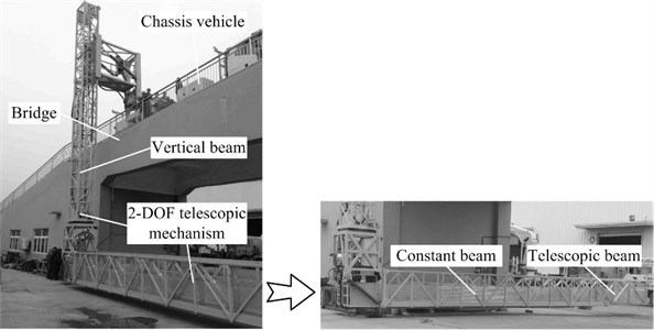
Truss structure bridge inspection vehicle (Fig. 1) provides work pass and plat, a 2-DOF telescopic mechanism composed by one vertical beam, one constant beam and one telescopic beam, for bridge maintenance. The vertical beam is vertically connected to the chassis and can move axially through guiding rails. The constant beam is generally perpendicularly fixed to the end of the vertical beam during work. Besides, the telescopic beam is connected axially to the constant beam using guiding rails. It is necessary to extend or retract the vertical beam and telescopic beam to reach a certain depth and width under the bridge. As a longspan, suspended and 2-DOF structure, the telescopic mechanism is vulnerable to vibration. For fear of large vibration, the workers generally move the beams separately. Nevertheless, they are expected to move synchronously to improve the work efficiency. Whether synchronous motion will lead to stronger vibration has no theoretical support. Therefore, dynamic behaviors of the 2-DOF axially telescopic mechanism should be focused on.
Many studies have been published over the years to investigate dynamic characteristics of axially moving structures. Wang and Wei [1] investigated vibration characteristics of an axially moving beam with the varying in the effective length considered. Behdinan et al. [2, 3] accounted for the small strains but large rotations of flexible sliding beams and derived the equations of motion for flexible sliding beams following the approach outlined by Vu-Quoc and Li [4] and obtained the transient responses by using Galerkin’s method. Fung et al. [5] used four dynamic models of Timoshenko, Euler, simple flexible and rigid body beams to describe axially moving beam under tip mass. Öz et al. [6, 7] studied the linear and nonlinear vibrations of axially moving beams by using the method of multiple scales. Chen and Zhao [8] presented a modified finite difference method to study the transverse vibration of axially moving string. Piovana and Sampaiob [9] addressed vibration characteristics of an axially moving flexible beam with tip mass by employing a finite element method based on beam-element of variable domain. Wang et al. [10, 11] analyzed the vibration characteristics of an axially moving cantilever beam and plate using the extended Hamilton’s principle. An and Su [12] used the generalized integral transform technique that features automatic and straightforward global error control to study the dynamic responses of axially moving beams. Liu et al. [13] acquired the analytical expression of the first-order approximate solution using the multiple scales to investigate the dynamic responses of an axially moving beam. Park et al. [14] compared the vibration responses of an axially moving beam with Eulerian and Lagrangian descriptions. Zhang et al. [15, 16] presented the nonlinear dynamic behaviors of axially moving cantilever beam and plate in large deformation by employing the Reddy’s third-order theory. These studies addressed dynamics of single axially moving beam, string or plate. Multiple axially moving beams have also been taken into account. Raftoyiannis and Michaltsos [17] established a dynamic analytical model to study the dynamic characteristics of a two-stage telescopic beams with the interaction between the beams equivalent as point forces. Duan et al. [18] obtained the relationship of the eigenfunctions for multiple cantilever beams and studied the transverse vibration characteristics of the axially moving beams. These studies accounted for structures moving axially in single direction. However, the coupling in the 2-DOF axially telescopic mechanism can be more complex, which hasn’t been investigated.
In this paper, dynamic behaviors of the 2-DOF axially telescopic mechanism for truss structure bridge inspection vehicle are analyzed. Sections 2 derives the equations of motion utilizing the Hamilton’s principle with the telescopic mechanism presented in Lagrangian description. The Galerkin’s method is adopted to discritize the equations in Section 3 and the time-dependent eigenfunctions are obtained according to the boundary conditions. Then the solutions are acquired using the Newmark- method. The experimental results are shown to verify the correctness of the theoretical model in Section 4. Further, the numerical results are presented to explore the influence of the extending or retracting strategy for the beams on the coupling dynamic behaviors of the telescopic mechanism.
Fig. 1Truss structure bridge inspection vehicle
2. Equations of motion of the dynamic model
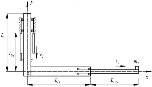
The model of the 2-DOF telescopic mechanism carrying a mass at the end is shown in Fig. 2. The Lagrangian description is adopted to establish the coordinate , the origin fixed at the end of the vertical beam and moving with the beams. and are the coordinate along the undeflected major axis of the constant and vertical beams, respectively. The linear densities of the vertical, constant and telescopic beams are , and ; the bending stiffnesses , and ; the lengths , and , respectively. and are the extensions of the vertical beam and telescopic beam. is the total length of the constant and telescopic beams. The velocities of the vertical beam and telescopic beam are and , separately. The mass at the end weighs . The Euler-Bernoulli beam theory is used to simplify the beams. The moments of inertia are neglected. The overlapped part in the telescopic mechanism is connected to the constant beam merely at the beginning and end and has little impact on the bending stiffness. Hence, it is simplified as external load at the end of constant beam.
Fig. 22-DOF axially moving telescopic mechanism system
The Hamilton’s principle is adopted to derive the equations of motion for the telescopic mechanism. The expression of the Hamilton’s principle reads:
in which is the kinetic energy, is the potential energy and is the virtual work.
1) Kinetic energy:
The total kinetic energy is determined by the vibrational energy and the kinetic energy of the motion for the beams:
where , and are the deflections of the vertical beam, constant beam and telescopic beam, separately, the superscripted dot means the time differentiation of the displacement.
2) Potential energy:
The total potential energy contains the bending energy and gravitational energy:
in which the prime denoted the differentiation of the deflection versus the spatial coordinate.
3) Virtual work:
The equivalent force of the overlap part in the telescopic beam to the end of the constant beam is given by:
in which:
The equivalent force from the mass at the end of the telescopic beam is:
Therefore, the virtual work to the telescopic mechanism is denoted as:
Consequently, applying the Hamilton’s principle, the equations of motion for the beams with respect to , and can be drawn:
where is the Dirac function.
3. Solutions to the equations
The vertical beam is slidingly contacted with fixed structure, the beginning of the constant beam is perpendicularly fixed to the end of the vertical beam and the beginning of the telescopic beam is a slidingly contacted with the constant beam as well. Accordingly, the kinematic boundary conditions and geometric continuity conditions are expressed in the following equations:
The Galerkin’s method is employed to truncate the vibration equation to a set of time-dependent ordinary differential equations. The deflections of the beams are respectively discretized as:
where is the space dimension, , and are the th eigenfunctions of the vertical beam, constant beam and telescopic beam, respectively, is the generalized coordinate. The eigenfunctions are expressed in the following formulation:
where , , , , , , , , , , and are the coefficients of the eigenfunctions, , and are the eigenvalues, defined as:
where is the th natural frequency.
Substituting the discretized deflections into Eq. (9) yields:
with the matrix:
and the vector of the unknown parameters:
As is shown, the eigenfunctions are time-dependent as the extensions of the vertical and telescopic beams are time-varying. The instantaneous eigenvalues and coefficients of the eigenfunctions are calculated by equaling the determinant of the coefficient matrix in Eq. (13) to zero and then applying the dichotomy method. The coefficients of the eigenfunctions are:
Substituting Eq. (10) to Eq. (8) and multiplying the equations with and separately and then summing them up, the discretized equations of motion for the telescopic mechanism can be obtained:
where:
in which:
The solutions to the equations of motion are acquired by employing the average acceleration method of the Newmark-.
4. Experimental and numerical results
4.1. Model verification with experiments
To verify the correctness of the theoretical model on the truss structure bridge inspection vehicle XCMG QJS20A, as displayed in Fig. 3. An accelerometer is installed at the end and vertical to the axis of the telescopic beam to capture the vibration. The data from the accelerometer are transmitted to a collector. The stiffnesses of the three beams are obtained by static test to be 120 MPa, 90 MPa and 140 MPa. Other specific properties of the beams are as follows: 15.3 m, 10.83 m, 10.74 m, 90 kg/m, 87.5 kg/m, 49.6 kg/m, 400 kg.
As the vertical and telescopic beams are not allowed to move synchronously at present, the experiments were implemented by extending and retracting the telescopic beam with the vertical beam fixed at the extension of 11 m. The extension process begins with the total length of the constant and telescopic beams being 11 m and the retraction process begins with the telescopic beam extended to its maximum length 20.05 m. The telescopic beam starts with an acceleration of 6 m/s2 from static and finally reaches a constant velocity of 0.317 m/s. The theoretical results of the dynamic responses for the first order model are compared with the experimental results, as presented in Fig. 4. As is seen, the theoretical results slightly deviate from the expermental results. This is becasue of the deviation in the measured beam stiffnesses, the influence of structural damping, the base on which the vertical beam fixed being not strictly static, the vibration from the motor and so on. However, it is determined that the theoretical results are consistent with the experiment results within tolerance. Hence, the effectiveness of the theoretical model can be verified.
Fig. 3Schematic diagram of the test platform
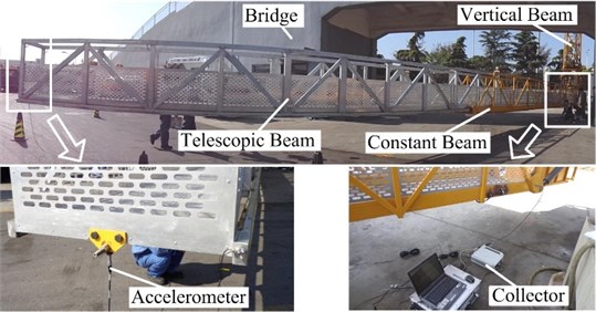
Fig. 4Dynamic behaviors of theoretical and experimental results
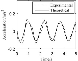
a) Extension
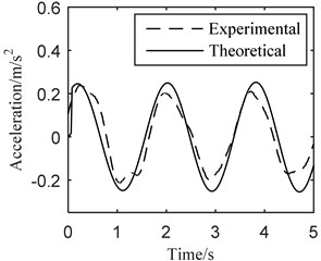
b) Retraction
4.2. Numerical results
Numerical examples are presented to investigate the influence of the beam moving strategy on the dynamic behaviors of the 2-DOF axially telescopic mechanism. The parameters of the beams are given based on a new truss structure bridge inspection vehicle, whose vertical and telescopic beams are expected to move synchronously, with 88 MPa, 35 MPa and 35 MPa, 15.3 m, 10.7 m, 10.7 m, 84 kg/m, 85 kg/m, 46 kg/m, 400 kg. The maximum extension of the vertical beam is 12.9 m and the total length of the constant beam and telescopic beam when fully extended is 20 m.
Fig. 5The first three modal shapes
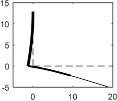
a) 1st mode
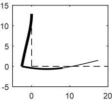
b) 2nd mode
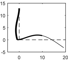
c) 3rd mode
The modal shapes of the beams are given in Fig. 5 for better understanding of the vibration characteristics. As the eigenfunctions of the beams are time dependent. The coefficients and eigenvalues are instantaneous parameters. The modal shapes when the beams all reach their maximum lengthes are displays in Fig. 5. Note that the dotted lines stand for the undeflected beams and the solid ones denote the modes. It can be acquired that the vertical beam features large vibrational amplitude and plays a significant role in the vibration of the three beams. Accordingly, the motion of the vertical beam has great influence on the dynamic behaviors of the whole structure.
Comparison when the vertical and telescopic beams moves separately and synchronously are implemented to achieve the influence of the beam moving strategy. There are four conditions of extending or retracting the vertical and telescopic beams to have the telescopic mechanism reach a certain position. Besides, different beam moving strategies, i.e., the vertical and telescopic beams moving axially synchronously, the vertical beam first (step 1) and then (step 2) the telescopic beam and the telescopic beam first (step 1) and then (step 2) the vertical beam, as listed in Table 1, in each condition are implemented to explore the influence of synchronous motion for the beams on the vibration. ‘+’ represents the beam extending out and ‘-’ retracting back. The beams are assumed to be static at the beginning of the extension or retraction. The vibrations of the end for the telescopic beams in the four conditions are shown in Figs. 6-9.
Table 1Vertical beam and telescopic beam extending or retracting strategies
Condition | / m/s | /m/s | / m | / m | ||
(I) Vertical beam + Telescopic beam + | Synchronously | 0.5 | 0.5 | 7.9 | 15 | |
Vertical beam first | Step 1 | 0 | 0.5 | 7.9 | 15 | |
Step 2 | 0.5 | 0 | 7.9 | 20 | ||
Telescopic beam first | Step 1 | 0.5 | 0 | 7.9 | 15 | |
Step 2 | 0 | 0.5 | 12.9 | 15 | ||
(II) Vertical beam - Telescopic beam - | Synchronously | –0.5 | –0.5 | 12.9 | 20 | |
Vertical beam first | Step 1 | 0 | –0.5 | 12.9 | 20 | |
Step 2 | –0.5 | 0 | 12.9 | 15 | ||
Telescopic beam first | Step 1 | –0.5 | 0 | 12.9 | 20 | |
Step 2 | 0 | –0.5 | 7.9 | 20 | ||
(III) Vertical beam + Telescopic beam - | Synchronously | 0.5 | –0.5 | 7.9 | 20 | |
Vertical beam first | Step 1 | 0.5 | 0 | 7.9 | 20 | |
Step 2 | 0 | –0.5 | 12.9 | 20 | ||
Telescopic beam first | Step 1 | 0 | –0.5 | 7.9 | 20 | |
Step 2 | 0.5 | 0 | 7.9 | 15 | ||
(IV) Vertical beam - Telescopic beam + | Synchronously | –0.5 | 0.5 | 12.9 | 15 | |
Vertical beam first | Step 1 | –0.5 | 0 | 12.9 | 15 | |
Step 2 | 0 | 0.5 | 7.9 | 15 | ||
Telescopic beam first | Step 1 | 0 | 0.5 | 12.9 | 15 | |
Step 2 | –0.5 | 0 | 12.9 | 20 |
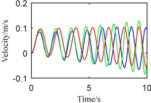
Fig. 6Dynamic behaviors when a) telescopic beam +, b) vertical beam +: (blue) synchronously, (green) step 1, (red) step 2
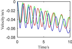
a)
b)
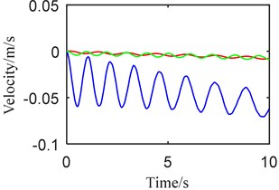
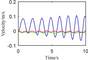
Fig. 6 presents the vibrational velocity corresponding to condition I. As is revealed, synchronous extension of the vertical and telescopic beams undergoes the maximum vibration in the three beam moving strategies. Besides, the separate extension of the telescopic beam performs slightly smaller vibration than the synchronous one. Moreover, the extension of the telescopic beam after the vertical beam gives rise to increasingly stronger vibration than that before the vertical beam, i.e., larger extension of the vertical beam increases the vibration in the extension of the telescopic beam. Nevertheless, the vibrations in the separate extension of the vertical beam are significantly smaller than that in the synchronous motion. Fig. 7 displays the vibrational velocity of the beams in condition II. The differences between the synchronous and separate motions of the vertical and telescopic beams are similar to those in condition I. In this condition, shorter extension of the vertical beam is in favor of enlarging the vibration in the retraction of the telescopic beam.
Fig. 7Dynamic behaviors when a) telescopic beam –, b) vertical beam –: (blue) synchronously, (green) step 1, (red) step 2
a)
b)
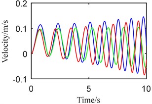
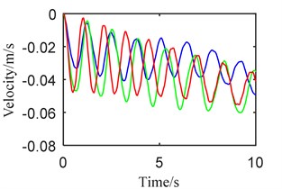
Fig. 8Dynamic behaviors when a) telescopic beam +, b) vertical beam –: (blue) synchronously, (green) step 1, (red) step 2
a)
b)
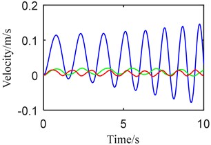
Fig. 9Dynamic behaviors when a) telescopic beam –, b) vertical beam +: (blue) synchronously, (green) step 1, (red) step 2
a)
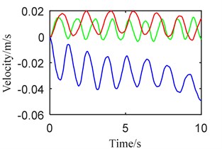
b)
The vibrational velocity in condition III is shown in Fig. 8. Different from that in condition I and II, the vibration when the telescopic beam moves before the vertical beam is larger than the other two; besides, the vibration in the synchronous retraction of the telescopic beam with the extension of the vertical beam is slightly smaller and that when the telescopic beam moves after the vertical beam is the minimum. Thus, in accord with that in condition II, smaller extension of the vertical beam will bring about larger vibration when the telescopic beam retracts back. Analogous to the aforementioned two conditions, the vibration when the vertical beam acts individually are greatly smaller than that in the synchronous motion.
Fig. 9 depicts the vibrational velocity corresponding to condition IV. As can be seen, the telescopic beam extending separately brings in stronger vibration than that acting synchronously with the retraction of the vertical beam. What’s more, the telescopic beam moving before the vertical beam leads to larger vibration than after the vertical beam, identical to the result that increase in the extension of the vertical beam leads to larger vibration in the separate extension of the telescopic beam. On the other hand, the vibration when the vertical beam retracts separately is smaller than that in the synchronous motion.
5. Conclusions
Dynamic behaviors of the 2-DOF telescopic mechanism for truss structure bridge inspection vehicle are studied. The vertical, constant and telescopic beams are simplified under the Euler-Bernoulli beam theory. The equations of motion in Lagrangian description are obtained based on the Hamilton’s principle. By means of the Galerkin’s method, the partial differential equations are transformed into a set of ordinary differential equations. The time-dependent eigenfunctions of the beams are acquired according to the time-varying boundary conditions utilizing the dichotomy method. The theoretical model is verified by experiments and numerical examples are presented to explore appropriate beam extending or retracting strategies to avoid large vibration and meanwhile improve the work efficiency.
In the whole process of extending or retracting the vertical and telescopic beams, synchronous motion will not always bring about larger vibration than separate ones. Besides, the vibrations in the synchronous motion are only slightly larger than those in the separate motions when the beams both extend out or retract back. Moreover, synchronous motion can even bring in smaller vibration than the separate one when one beam extends out and the other retracts back. Therefore, to improve the work efficiency, synchronous extension or retraction can be implemented. On the other hand, larger extension of the vertical beam results in stronger vibration when the telescopic beam extends out and weaker when retracting back. Therefore, on condition of separate extension or retraction, when the beams all extend out or retract back, the telescopic beam should move before the vertical beam; nevertheless, when one extends out and the other retracts back the telescopic beam should move after the vertical beam.
References
-
Wang P. K. C., Wei J. D. Vibrations in a moving flexible robot arm. Journal of Sound and Vibration, Vol. 116, Issue 1, 1987, p. 149-160.
-
Behdinana K., Stylianoub M. C., Tabarrokc B. Dynamics of flexible sliding beams – non-linear analysis, part I – formulation. Journal of Sound and Vibration, Vol. 208, Issue 4, 1997, p. 517-539.
-
Behdinan K., Tabarrok B. Dynamics of flexible sliding beams – non-linear analysis, part II – transient response. Journal of Sound and Vibration, Vol. 208, Issue 4, 1997, p. 541-565.
-
Vu-Quoc L. S. Dynamics of sliding geometrically exact beams: large angle maneuver and parametric resonance. Computer Methods in Applied Mechanics and Engineering, Vol. 120, Issue 2, 1995, p. 65-118.
-
Fung R. F., Lu P. Y., Tseng C. C. Non-linearly dynamic modelling of an axially moving beam with a tip mass. Journal of Sound and Vibration, Vol. 218, Issue 4, 1998, p. 559-571.
-
Öz H. R., Pakdemiorli M. Vibrations of an axially moving beam with time-dependent velocity. Journal of Sound and Vibration, Vol. 227, Issue 2, 1999, p. 239-257.
-
Öz H. R., Pakdemiorli M., Boyacm H. Non-linear vibrations and stability of an axially moving beam with time-dependent velocity. Journal of Sound and Vibration, Vol. 36, Issue 2001, 1999, p. 107-115.
-
Chen L. Q., Zhao W. J. A numerical method for simulating transverse vibrations of an axially moving string. Applied Mathematics and Computation, Vol. 160, Issue 2, 2005, p. 411-422.
-
Piovana M. T., Sampaiob R. Vibrations of axially moving flexible beams made of functionally graded materials. Thin-Walled Structures, Vol. 46, Issue 16, 2008, p. 112-121.
-
Wang L. H., Hu Z. D., Zhong Z., Ju J. W. Hamiltonian dynamic analysis of an axially translating beam featuring time-variant velocity. Acta Mechanica, Vol. 206, Issues 3-4, 2009, p. 149-161.
-
Wang L. H., Hu Z. D., Zhong Z., Ju J. W. Dynamic analysis of an axially translating plate with time-variant length. Acta Mechanica, Vol. 215, Issue 1, 2010, p. 9-23.
-
An C., Su J. Dynamic response of clamped axially moving beams: integral transform solution. Applied Mathematics and Computation, Vol. 218, Issue 2, 2010, p. 249-259.
-
Liu D., Xu W., Xu Y. Dynamic responses of axially moving viscoelastic beam under a randomly disordered periodic excitation. Journal of Sound and Vibration, Vol. 331, Issue 17, 2012, p. 4044-4056.
-
Park S., Yoo H. H., Chung J. Eulerian and Lagrangian descriptions for the vibration analysis of a deploying beam. Journal of Mechanical Science and Technology, Vol. 27, Issue 9, 2013, p. 2637-2643.
-
Zhang W., Sun L., Yang X. D., Jia P. Nonlinear dynamic behaviors of a deploying-and-retreating wing with varying velocity. Journal of Sound and Vibration, Vol. 332, Issue 25, 2013, p. 6785-6797.
-
Zhang W., Lu S.F., Yang X.D. Analysis on nonlinear dynamics of a deploying composite laminated cantilever plate. Nonlinear Dynamics, Vol. 76, Issue 1, 2014, p. 69-93.
-
Raftoyiannis I. G., Michaltsos G. T. Dynamic behavior of telescopic cranes boom. International Journal of Structural Stability and Dynamics, Vol. 13, Issue 1, 2013, p. 1350010.
-
Duan Y. Ch., Wang J. P., Wang J. Q. Theoretical and experimental study on the transverse vibration properties of an axially moving nested cantilever beam. Journal of Sound and Vibration, Vol. 333, Issue 13, 2014, p. 2885-2897.
Cited by
About this article

This research was supported by the Program for Changjiang Scholars and Innovative Research Team in University (Grant No. IRT1292) and the Priority Academic Program Development of Jiangsu Higher Education Institutions. The authors would like to thank the editors, associate editors and anonymous reviewers for their constructive comments.
