Abstract
The parallel mechanism was adopted as seat suspension system in this paper. And the active joints with damping springs as the reduction vibration actuator, the reduction vibration seat model with 3-PRPS parallel mechanism which had six degree of freedom was established. With position of the mechanism as the premise, stability indexes of the reduction vibration seat in motion were proposed. As a result, the task space of the moving platform was obtained according to the inverse solution of the mechanism position. To reduce vibration effectively, velocity matrix of branched chain was built by means of vector method. The structural parameters were obtained by the numerical computation to improve the reduction vibration space and flexibility. Based on the above analysis, the simulation model can be obtained. In order to verify the reliability of the simulation model, the experiment of vibration acceleration transmissibility was conducted and the result was then compared with that of the numerical computation. Their results were consistent with each other. It indicated that the simulation model was reliable and could be used for the subsequent analysis. Then, influence factors of vibration acceleration transmissibility were researched based on the verified simulation model. In order to obtain a suspension system with better reduction vibration performance, making the maximum vibration acceleration transmissibility in the vertical and horizontal be minimal was set as the optimization objective. And the above influence factors were taken as the design variables. Finally, the ride comfort of vehicles was improved. Meanwhile, this research can also provide some references for the similar engineering problems.
1. Introduction
Vehicles will bear the vertical vibration when running on uneven roads, front-back vibration when braking, and left-right vibration when turning. The combination of these vibrations can be regarded as multidimensional vibration. For a long time, the reduction vibration in the ordinary vehicle seats feature a simple design and mostly have a simple X-type structure. X-type structures can only reduce vertical vibration, and cannot reduce vibrations in other directions [1]. Therefore, a multidimensional reduction vibration which can reduce the vibration in multiple directions is of large research significance. Few ways are currently available for multidimensional reduction vibration. In references [2-4], only the effect on the vertical vibration was considered, mainly because the studied seat suspension system could only allow movement in a single direction and therefore the research on the multidimensional reduction vibration for the vehicle seats was not feasible. Reference [5] proposed a three-dimensional vibration control suspension for ambulances, but the structure of this suspension was too complex: it used a mechanical multilayer reduction vibration structure with a single degree of freedom. The parallel mechanism was a multi-input and multi-output system with multiple degrees of freedom. Supposing that the parallel mechanism platform was excited by multidimensional vibration, its multidimensional vibration can be reduced by installing controllable elastic damping vibration system on the movement position. In order to realize the multidimensional vibration control, Ma proposed a parallel mechanism with six degrees of freedom (Stewart platform) and four degrees of freedom [6], but the reliability of this multidimensional reduction vibration has not been verified by experiment. Wu proposed a 3D parallel mechanism and applied it to the vehicle seat, but he only analyzed the reduction vibration in the vertical direction, and didn’t take into account the effect in other directions [7]. Yang designed a multidimensional reduction vibration seat based on the parallel mechanism. However, his analysis was only based on the numerical simulation, the parallel mechanism was also simplified, and the computational results were not verified [8]. A number of researches have been conducted on the semi-active control of seat reduction vibration [9, 10], and despite the satisfactory effect of reduction vibration, this type of control mechanism requires high cost and complex design. Such seat reduction vibration structures are mostly applied to luxury vehicles, and are not suitable for the economical vehicles. Moreover, in the mentioned researches, the size of the parallel mechanism is not further optimized, and the designed parallel mechanisms may not have the optimal reduction vibration performance.
In this paper, the controllable and precise [11, 12] 3-PRPS parallel mechanism with six degree of freedom was adopted as the suspension system of the multi-dimensional reduction vibration seat. The active joints were accompanied with damping systems to achieve energy absorption and dynamic self-adapting balance. As a result, the physical and psychological harm to drivers due to the strong vibrations were reduced. With position of the mechanism as the premise, stability indexes such as task space and flexibility were proposed. Then, the structural parameters were obtained by the numerical computation to improve task space and flexibility. Based on the above analysis, the simulation model can be obtained. In order to verify the reliability of the simulation model, the experiment of vibration acceleration transmissibility was conducted and its result was then compared with that of the numerical computation. Their results were consistent with each other. It indicated that the simulation model was reliable and could be used for the subsequent analysis. Then, influence factors of vibration acceleration transmissibility were researched based on the verified simulation model. In order to obtain a suspension system with a better reduction vibration performance, making the maximum vibration acceleration transmissibility in the vertical and horizontal be minimal was set as the optimization objective. And the above influence factors were taken as the design variables. Finally, the ride comfort of vehicles was improved. Meanwhile, this research can also provide some references for the similar engineering problems.
2. The establishment of mechanical model and the solution of Jacobian matrix
2.1. The establishment of 3-PRPS parallel mechanism
Fig. 1(a) showed the multidimensional parallel mechanism designed in the paper for realizing multidimensional reduction vibration. It consisted of moving platform , fixed platform and symmetrical branches connecting two platforms. And each branch was composed of (---). Both the moving platform and the fixed platform were equilateral triangles. The radius of the circum-circle for the moving platform was and the radius of the inscribed circle for the fixed platform was . According to the characteristics of 3-PRPS parallel mechanism, the fixed coordinate system - was established on the orthocenter of the fixed platform and moving coordinate system - was established on the orthocenter of the moving platform. For vehicle seats, the rotational degree of freedom was generally constrained and only the translational degrees of freedom are flexible, thus the reduction vibration mechanism only had to reduce the translational degrees of freedom in the horizontal and vertical directions. As shown in Fig. 1(b), the seats of the traditionally economical vehicles usually used X-type reduction vibration mechanism, which can only reduce the vertical vibration and cannot effectively reduce the horizontal vibration. The multi-dimensional parallel mechanism presented in this paper, as shown in Fig. 1(a), can not only reduce the vertical vibration, but also obviously reduce the horizontal vibration. In order to verify this conclusion, the vibration test platform in the paper was used for testing the reduction vibration performances of the parallel mechanism and X-type mechanism, as shown in the following contents.
Springs and damping devices were established on moving pair and the contact position . The vertical rod length changes and horizontal movement of could be realized based on elastic supports. As a result, the reduction vibration with six-dimensional direction was realized.
Fig. 1Diagram of parallel mechanism and X-type mechanism
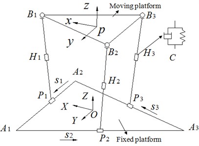
a) 3-PRPS parallel mechanism
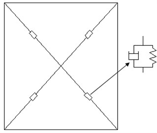
b) X-type mechanism
2.2. The solution of speed and acceleration of the mechanism
Fig. 2 only showed the sketch of the parallel mechanism in Fig. 1(a) in order to facilitate the theoretical analysis. The single chain vector of the mechanism was established.
The following formula can be obtained for Fig. 2:
Eq. (1) can also be changed into two formulas as follows:
and were substituted into Eqs. (2) and (3). Meanwhile, the following formulas can be obtained based on derivative to time:
where and are the displacement of the horizontal slider at the chain and the length of longitudinal connecting rod, respectively.
The following formulas can be obtained by solving the derivative of Eq. (6), and then Eqs. (4) and (5) should be combined the derivative of Eq. (6):
The derivative to time is obtained further as follows:
and are set as the unit vector of the sliding along the direction of and , so we can obtained two formulas as follows:
In addition, the speed of point can be expressed as follows:
where , are the linear and angular velocities of point in the moving platform, respectively:
and are set as the velocity and acceleration of the position of the moving platform, respectively. And then we can obtain the following formula:
Eq. (14) was written in matrix type as follows:
The following formulas can be obtained by combining the above formulas:
where and are the input and output speed matrix of the mechanism, respectively. and are the first-order influence coefficient matrix and second-order influence coefficient matrix of the input speed to moving platform velocity, respectively.
Fig. 2Single chain vector diagram of the mechanism
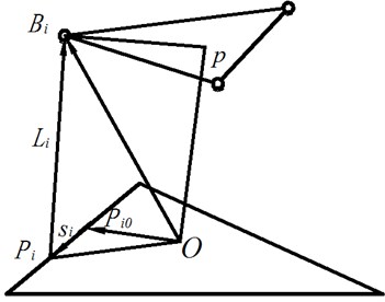
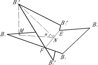
Fig. 3Dynamic change of suspension system
3. The stability index and determination of size parameters
3.1. The stability index
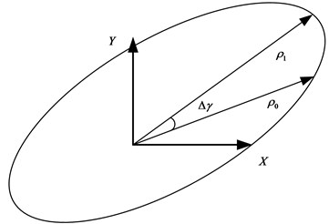
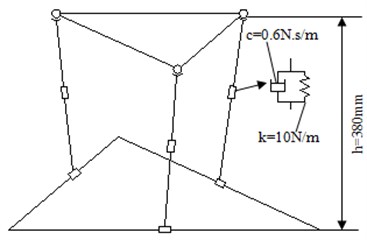
In this paper, the stability index of suspension system for the reduction vibration seat was proposed. As shown in Fig. 3, the moving platform was the initial position of suspension system and was parallel to the horizontal plane. was defined as the angle between suspension system and the horizontal plane, in addition, . The workspace of suspension system was affected by . Therefore, seeking an appropriate was very important for the optimization of suspension system. As a result, was taken as 30° for the comfort of the reduction vibration seat.
As we all know, the position coordinate of the moving platform did not affect . The size of was only determined by Euler angles , , . The initial position of the moving platform was set as , and it would be after moving. We could know from the inverse solution [13] of position for suspension system that the coordinates of , , can determine the plane equation of the moving platform after moving and obtain the normal vector . The normal vector of the initial position for the moving platform was and then it can be expressed as follows:
Eq. (22) shows that , and and represent Euler angles formed between the rotated plane of the moving platform and the horizontal plane. As shown in this paper, 30°, so . and are changed at any time based on the rotation of the moving platform. In the working process of the parallel mechanism, every angle is corresponded to a angle. And the range of and should be ensured their continuous variation in the working process of the moving platform, in order to be applied in practical engineering. Besides, let the above equation be constantly real; as a result, should be equal to , then . Through solving this inequality, we can obtain the following relation: –19.7331° 19.7331°. If is unequal to , is given a larger angle while is assigned a smaller angle. In this case, the above inequality can be satisfied as well. Nevertheless, the discontinuous change of positions for the mechanism is caused in the working process, which is inconsistent with the actual situation. And the solving process for is similar to this. And Eq. (23) can be finally obtained as follows:
had nothing to do with , we took the range of as –20°20°. At the same time, the translational capacity of the moving platform should be limited as follows. –60 mm 60 mm, –60 mm 60 mm, –60 mm 60 mm, were the maximum distance of the moving platform along the axis of the fixed coordinate.
3.2. Determination of size parameters
For suspension system, the structural parameters directly affected the final reduction vibration effect. So it was important to decide parameters. They can be selected from the task space and flexibility.
3.2.1. Task space
In the practical problems, it was hoped that the structural parameters of the design can maximize the volume of the moving platform within a given task space, in order to provide the reduction vibration platform with a good reduction vibration space and therefore improve the effect. In this paper, Monte Carlo (MC) method was used to optimize the task space for the parallel mechanism. Monte Carlo method, also called the limit boundary search method, was a search method based on the inverse solution of the kinematical position for the parallel mechanism. Its principle was as follows: firstly, defined a range that contains all the possible task space for the parallel mechanism. Then, generated a large number of random points in this range, and then, judged whether each of the points was within the task space based on the constraint condition. Points that met the constraint condition will be regarded as ones in the task space, while those which did not meet the condition will be removed. All the available points constituted the task space of the parallel mechanism. And the points located between the available points and the unavailable ones were the boundary points for the task space, and they formed the boundary line [14, 15].
The detailed search steps of the MC method were as follows:
1) Estimated the range of the task space based on the specific structural parameters of the parallel mechanism.
2) Divided this space into subspaces with a width of by using planes which were paralleled to the - plane, and searched along the -axial direction.
3) Got the rotational angle of the Hooke’s joints in each subspace. When the solving process changed from the available inverse solution to the unavailable inverse solution, the corresponding point was considered as the task-space boundary point. And the set of the obtained points was the boundary line for the task space, as shown in Fig. 4.
Fig. 4The sectional view of the task space
4) Searched for all the task-space boundary points in the subspaces, and then used these points to generate the envelope surface of the task space. As a result, the points within this space constituted the task space of the parallel mechanism. The search process for the whole task space by using MC method was shown in Fig. 5.
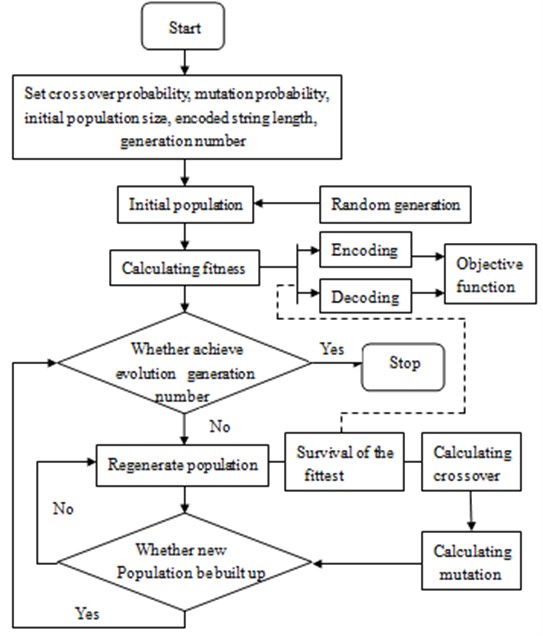
In addition, the optimization process for the whole task space by using genetic algorithm was also conducted, as shown in Fig. 6.
1) Chromosome coding. Chromosomes should be coded before the searching process of genetic algorithm. In the paper, every solution in the search space was regarded as a chromosome.
2) Initial population. Size of the initial population was set to be 50.
3) Calculating fitness. Fitness was used to evaluate the individual. The greater the fitness was, the better the individual is. Dependent on the value of fitness, individuals were selected so as to ensure individuals with better fitness to have more opportunities in reproduction
4) Selection. Individuals which showed relatively stable fitness during evolution were selected.
5) Crossover. Some chromosomes among 50 individuals were exchanged under a probability. 50 new individuals were then generated. The crossover probability was set to be 0.85.
6) Mutation. Mutation was carried out to the selected 50 individuals according to the given probability. A new generation group was then formed. The mutation probability in this paper was 0.05.
7) Judgment. Whether the new generation group could satisfy constraint conditions was judged. If the conditions could be satisfied, the operation would be stopped, otherwise, step 3 would be continued.
Fig. 5The search process for the task space by using MC method
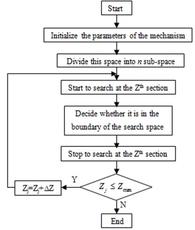
Fig. 6Optimization process of genetic algorithm
The task space optimized by MC method and GA was shown in Table 1. According to Table 1, the task space of the parallel mechanism obtained by using MC method was obviously larger than that of genetic algorithm. The main reason was that MC method can make global optimization, whereas genetic algorithm had a poor global-optimization capacity and often obtain locally optimal solution. Therefore, it was necessary to optimize the task space for the parallel mechanism by using MC method.
Table 1Comparison of task space between MC method and GA
Size of task space | Monte Carlo method | Genetic algorithm | |
direction (mm) | Upper limit | 100 | 100 |
Lower limit | –79 | –40 | |
direction (mm) | Upper limit | 100 | 100 |
Lower limit | –72 | –11 | |
direction (mm) | Upper limit | 292 | 305 |
Lower limit | 100 | 240 | |
3.2.2. Flexibility
We expected suspension system to be flexible enough and can be used to reduce influences from the outside so that shock and strong vibration cannot affect the comfort.
The movement performance of suspension system in the workspace was evaluated by the global performance indexwhich was proposed by Cosselin [16]:
where was the number of conditions for first-order influence coefficient (or Jacobian matrix). was the reachable task space of suspension system. The greater the , the higher the flexibility and control accuracy were and the better the performance was.
3.2.3. Value of size parameters
By analyzing the stability, the position of the moving platform and the range of the position were initially determined. From the ergonomics’ [17] point of view, the drivers’ seat of vehicles was 360 mm-480 mm high, 370 mm-420 mm wide and 360 mm-390 mm deep. According to the structural characteristics of suspension system, the radius of the circum-circle for the moving platform was set as 200 mm. Influence factors of the structural parameters were shown as follows.
1) The ratio was . was the initial height difference between the moving and fixed platform, and was the radius of the circum circle for the moving platform.
2) The ratio was . was the radius of the inscribed circle for the fixed platform, and r was the radius of the circum-circle for the moving platform.
3) Constraints of the intersection angle for the revolute pair should be also constrained. The vice rotation angle was constrained by the longitudinal connecting rod and the initial position . should meet the following constraints. . Constraints of parameters for suspension system were shown as follows:
According to the theory of MC method, there are a large number of sampling points in the search process. In this paper, the mean value of the sampling points in the fixed space is used to measure the size of the task space for the parallel mechanism. Therefore, the ratio (relative size) of the available sampling-point space to the research space , namely , can be used as the standard for measuring the size of the task space. After obtaining the task space shown in Comment 4 by using MC method, the relative size of the parallel mechanism for each and can be obtain by combining this space with the sampling-point space. Through multiple optimizations of the task space with changing the values of and , the results shown in Fig. 7(b) and Fig. 8(b) can be obtained.
In this paper, the global performance indexis used to evaluate the kinematic performance of the mechanism within the whole task space. The larger value is, the greater the dexterity and control accuracy of the mechanism will be, and the better the performance will be. Similarly, after obtaining the task space by using MC method, the reciprocal of the global performance index of the parallel mechanism for each and can be obtained based on other equations in the paper. Through multiple optimizations of the task space with changing the values of and , the results shown in Fig. 7(a) and Fig. 8(a) can be achieved.
Fig. 7Change curve of the relative volume and condition number with q
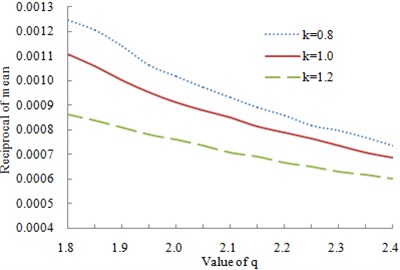
a) The reciprocal of mean for condition number was changing with
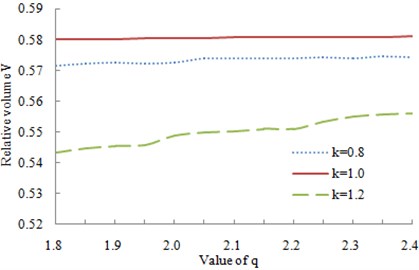
b) The relative volume was changing with
Fig. 8Change curve of the relative volume and condition number with k
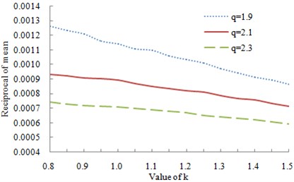
a) The reciprocal of mean for condition number was changing with
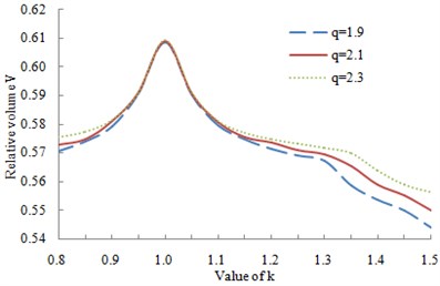
b) The relative volume was changing with
As known from Fig. 7(a) and Fig. 8(a), with the increasing of and , the reciprocal of mean for condition number reduced gradually. In other words, the flexibility of the mechanism reduced. When 1.9 and 1, the reciprocal of mean for condition number decreased the most sharply and the flexibility of the mechanism was the most prominent. As known from Fig. 7(b) and Fig. 8(b), the volume of the mechanism in motion reached the maximum at 1 and the fluctuation was the most obvious. The relative volume had no obvious relation with the change of .
Therefore, taking work space and flexibility into consideration, we chose 1.9 and 1.
4. Experiment of vibration acceleration transmissibility and verification of the simulation model
Selected suspension system was tested in the laboratory to verify the simulation model. Suspension system was mounted on a vibration platform, as shown in Fig. 9, and loaded with one mass block representing mass of the driver and seat. The total mass of the major people and seat was only less than 96 kg. As a result, mass block was set as 96 kg. Suspension system can simulate the actual situation by means of electro-hydraulic shaker. There was an acceleration sensor under mass block to test vibration acceleration of the moving platform, and this was a three-direction acceleration sensor, which could simultaneously measure the horizontal and vertical vibration accelerations, as shown in Fig. 10(a). The experimental data were recorded with multi-channel data acquisition equipment, as shown in Fig. 10(b). The time of each measurement was 6 s, the measurement for each group of data was repeated three times, and the averages of the data in the three measurements were used as the final results. The experiment was conducted in a semi-anechoic chamber to avoid the impact of the external environment on the experimental result. The tested horizontal and vertical vibration accelerations by using the parallel mechanism as the seat suspension were as shown in Fig. 11(a) and Fig. 12(a). In order to verify the reduction vibration effect of the parallel mechanism, the vibration acceleration of the traditional X-type mechanism was then tested, as shown in Fig. 11(b) and Fig. 12(b). Through comparing the vibration accelerations of two mechanisms, it can be seen that in the same excitation, X-type mechanism had little reduction vibration in the horizontal direction while the parallel mechanism proposed in this paper significantly reduced the horizontal vibration. Although X-type mechanism could effectively reduce the vertical vibration, the vibration peak of X-type mechanism was still greater than that of the parallel mechanism. Therefore, the parallel mechanism proposed in this paper was of great significance and engineering value.
Fig. 9Diagram of testing vibration platform for suspension system
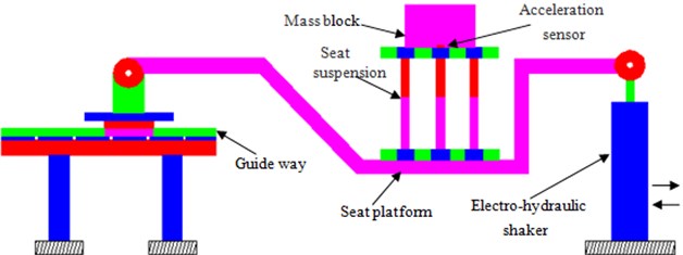
Fig. 10The equipment for testing the reduction vibration performance of the parallel mechanism
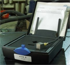
a) Acceleration sensor
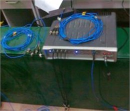
b) Data collection equipment
Traditionally, the ride comfort of a vehicle is evaluated by people in the vehicle, but this way lacks objectivity. In this paper, the vibration accelerations of the fixed platform and moving platform for the parallel mechanism were measured, before the vibration acceleration transmissibility of the parallel mechanism was computed. And transmissibility was used to reflect the reduction vibration performance of the parallel mechanism. The method by using transmissibility as the parameter for reflecting the seat suspension’s performance has been mentioned in many published papers. For example, Choi tested the transmissibility of the semi-active suspension seat, and also studied the effect of some parameter changes on the vibration transmissibility, and the experimental process was similar to the one in this paper [10]. Wang tested the vibration transmission of commercial-vehicle seats, built the corresponding multi-body dynamics model for simulation, and compared the computational results with the experimental results for verification [18]. Bouazara also analyzed the ride comfort and safety through testing the transmissibility of the seat suspension [19]. The reason that directly testing the transmissibility of the seat suspension is the most common approach is that transmissibility, as a natural characteristic of the seat suspension mechanism, will not be significantly affected by the external factors and can effectively reflect the natural reduction vibration performance of the mechanism. The transmissibility of this mechanism is determined by its design structure, and will not be changed unless some natural parameters of the mechanism are changed.
Fig. 11Vibration acceleration in the horizontal direction for two kinds of mechanism
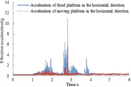
a) 3-PRPS parallel mechanism
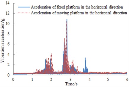
b) X-type mechanism
In addition, the test platform in this paper was designed specially to test the vibration characteristic of the seat. The tests in many published papers were also conducted based on this type of platform, and this test could effectively reflect the reduction vibration performance of the parallel mechanism.
Based on the tested vibration accelerations of the fixed platform and moving platform for the parallel mechanism, the corresponding vibration acceleration transmissibility can be computed. Suspension system was tested for constant amplitude sinusoidal excitations (wavelength is 1.25 cm, 2.5 cm and 3.75 cm, respectively) in the frequency range 0.5-0.8 Hz. The vertical and horizontal vibration acceleration transmissibility of suspension system was evaluated and presented in Fig. 13. The suspension system tends to break away at an excitation frequency of approximately 1.4 Hz corresponding to 1.25 cm excitation. The break frequencies corresponding to 2.5 cm and 3.75 cm excitations were observed to be 1.1 Hz and 0.9 Hz, respectively. The acceleration transmissibility characteristics of suspension system, adjusted to mid-ride position, exhibited resonant frequencies around 2.0 Hz, 1.75 Hz and 1.5 Hz, corresponding to 1,25 cm, 2,5 cm and 3.75 cm excitations, respectively. Vibration acceleration transmissibility at resonant points increased as the amplitude of excitation was increased.
Fig. 12Vibration acceleration in the vertical direction for two kinds of mechanism
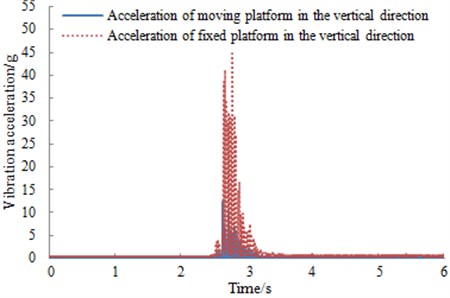
a) 3-PRPS parallel mechanism
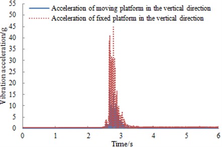
b) X-type mechanism
If we always researched vibration acceleration transmissibility by means of experiment, it will reduce efficiency. As a result, it was very necessary to simulate vibration acceleration transmissibility of suspension system.
According to the above analysis, we selected the structural parameters of suspension system as follows, 200 mm (radius of the circumscribed circle around the moving platform), 200 mm (radius of the inscribed circle within the fixed platform) and 380 mm. The simulation model was shown in Fig. 14(a). In order to verify the reliability of the simulation model, we took the loading mass of the moving platform as 96 kg which was same as the experimental one. Stiffness coefficient was 10 N/mm, and damping coefficient was 0.6 N∙s/mm. The positions of the above parameters in the simulation model are as shown in Fig. 14(b). Then we applied the constant amplitude sinusoidal excitations at the center of the moving platform. Vibration acceleration transmissibility of suspension system will be obtained, and then it was compared with that of the experiment, as shown in Fig. 15.
As can be seen from Fig. 15, the experimental results were consistent with that of the simulation model no matter in the trend or value, and the maximum relative error was less than 5 %. It indicated that the simulation model was reliable and could be used for the subsequent analysis.
Fig. 13Measured vibration acceleration transmissibility of a suspension system under different amplitudes of harmonic excitations
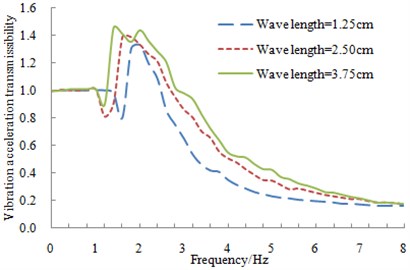
a) Vibration acceleration transmissibility of suspension system in the vertical direction
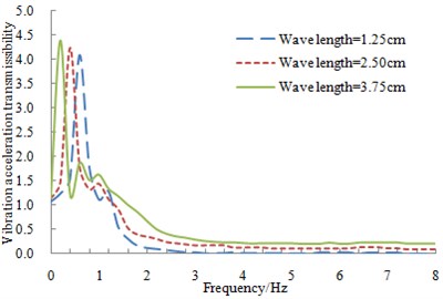
b) Vibration acceleration transmissibility of suspension system in the horizontal direction
Fig. 14The simulation model of suspension system
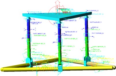
a) The simulation model
b) The sketch of the simulation model
Fig. 15Comparison of vibration acceleration transmissibility between experiment and simulation
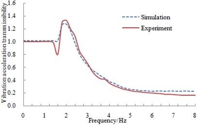
a) Comparison of vibration acceleration transmissibility in the vertical direction
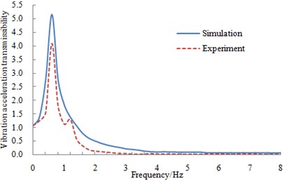
b) Comparison of vibration acceleration transmissibility in the horizontal direction
5. Influence factor analysis of vibration acceleration transmissibility
Since the interior layout space of vehicles was small, the size of suspension system was difficult to be changed. Therefore, only three parameters such as stiffness, damping and loading mass were selected to observe its reduction vibrations ability.
5.1. Influence of stiffness on vibration acceleration transmissibility
The loading mass and damping of the suspension system were 96 kg and 0.6 N∙s/mm, respectively, while its stiffness was changed from 5 N/mm to 20 N/mm and the change step length was 5 N/mm. The verified simulation model was applied to compute the vertical and horizontal vibration acceleration transmissibility of suspension system under different stiffness’s, as shown in Fig. 16.
As seen from Fig. 16, the vertical vibration acceleration transmissibility of suspension system was amplified regionally at the low frequency range. And then vibration acceleration transmissibility was reduced with the increases of excitation frequency, which was consistent with vibration acceleration transmissibility of the general passive vibration isolation system [20]. In addition, the change trends in the horizontal and vertical were similar. From comparison of Fig. 16(a) and Fig. 16(b), it can be seen that under the same stiffness, damping and loading mass, the maximum horizontal vibration acceleration transmissibility of suspension system was significantly higher than the corresponding value in the vertical direction. It was mainly because the equivalent damping in the horizontal direction was smaller than that of the vertical direction. As a result, ability of reduction vibration was weak and vibration acceleration transmissibility was relatively big.
Fig. 16Vibration acceleration transmissibility with different stiffness
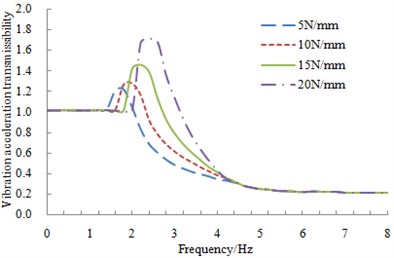
a) Vibration acceleration transmissibility with different stiffness in the vertical direction
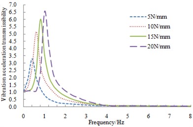
b) Vibration acceleration transmissibility with different stiffness in the horizontal direction
5.2. Influence of damping on vibration acceleration transmissibility
The loading mass and stiffness of suspension system were 96 kg and 10 N∙s/mm, respectively, while its damping was changed from 0.2 N∙s/mm to 0.8 N∙s/mm and the change step length was 0.2 N∙s/mm. The verified simulation model was applied to compute the vertical and horizontal vibration acceleration transmissibility of suspension system under different dampings, as shown in Fig. 17.
As seen from Fig. 17, the change trend of vibration acceleration transmissibility of suspension system under different dampings was basically same as that under different stiffness. However, the resonant frequencies of suspension system were consistent with each other under different dampings. Vibration acceleration transmissibility of suspension system was different in the resonant frequencies. With the increases of the damping, vibration acceleration transmissibility in the resonant frequencies was reduced, which was mainly due to that the damping can reduce vibration. When the bottom of suspension system was excited, the vibration would be absorbed and dissipated by the damping. As a result, the upper vibration acceleration of suspension system would be reduced. Therefore, vibration acceleration transmissibility would be decreased with the increase of the damping.
5.3. Influence of loading mass on vibration acceleration transmissibility
The stiffness and damping of suspension system were 10 N/mm and 0.6 N∙s/mm, respectively, while its loading mass was changed from 86 kg to 116 kg and the change step length was 10 kg. The verified simulation model was applied to compute the vertical and horizontal vibration acceleration transmissibility of suspension system under different loading mass, as shown in Fig. 18.
As seen from Fig. 18, vibration acceleration transmissibility was reduced gradually with the increase of loading mass before 2.2 Hz. This was mainly because the larger loading mass was, the bigger the inertia was. As a result, the motion state of suspension system was relatively difficult to change. Therefore, when the bottom of suspension system was excited and the upper was loaded with bigger mass, small vibration acceleration transmissibility would be appeared.
Fig. 17Vibration acceleration transmissibility with different damping
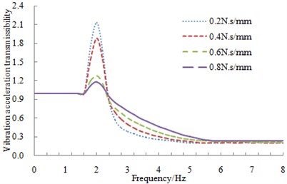
a) Vibration acceleration transmissibility with different damping in the vertical direction
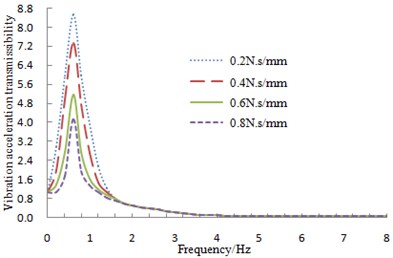
b) Vibration acceleration transmissibility with different damping in the horizontal direction
Fig. 18Vibration acceleration transmissibility with different loading mass
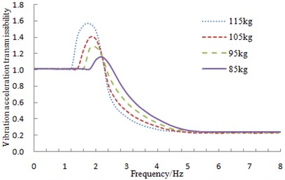
a) Vibration acceleration transmissibility with different loading mass in the vertical direction
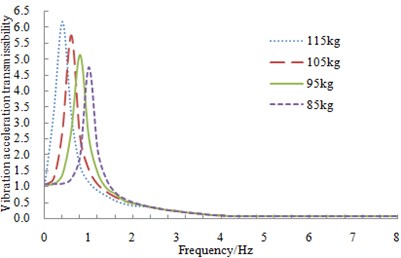
b) Vibration acceleration transmissibility with different loading mass in the horizontal direction
6. The optimization of vibration acceleration transmissibility for suspension system
From the above analysis, it could be found that a suspension system with the optimal reduction vibration performance was very difficult to obtain only by the simple combination of various parameters. However, these above researches also provided a certain reference for the following optimization design. In other words, the variables might be designed according to the mentioned parameters such as stiffness, damping, and loading mass. In addition, the analysis of influence factors also indicated that suspension system had shown obvious changes in both the vertical and horizontal vibration acceleration transmissibility with the change of design variables. Therefore, both the vertical and horizontal vibration acceleration transmissibility should be considered for the optimization design of suspension system, which was a multi-objective optimization problem.
6.1. Optimization method
In many cases, the sub-objective of the multi-objective optimization problem was often conflicting. The improvement of a certain sub-objective was likely to cause the deterioration of the other sub-objectives. As a result, there was no such a solution which can make many sub-objectives be the optimal. The final result of the multi-objective optimization problems can be obtained only by the coordination between each sub-objective, and each sub-objective can reach the optimal as much as possible. Non-dominated Sorting Genetic Algorithm (NSGA) was a multi-objective optimization algorithm based on the optimal conception of Pareto, which can solve the multi-objective optimization problem better.
6.2. Optimization process and result
Making the maximum vibration acceleration transmissibility in the vertical and horizontal be minimal was set as the optimization objective. According to the requirements of human sensitive frequency, four constraints were set to limit the resonant frequencies and vibration displacements and in the vertical and horizontal, respectively:
Based on the above analysis, the selected design variables for the optimization were stiffness, damping and loading mass of suspension system in this paper. During the execution of NSGA algorithm, the genetic population had 36 individuals. There were 60 generation evolutions during the optimization design. The individual crossover probability was 0.9, and the mutation probability was 0.05. When the weight of two optimization objectives was same as each other, Pareto solutions and the optimal solutions corresponding to the objective function distribution space were obtained, as shown in Fig. 19.
Fig. 19Comparison between Pareto solutions and the optimal solutions
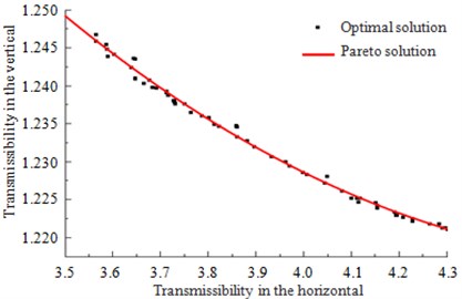
According to the definition of Pareto solutions, it was infinitely close to the actually optimal solution. And each solution of Pareto solution had no any superiority and inferiority. As shown in Fig. 19, the change range of the horizontal vibration acceleration transmissibility corresponding to Pareto solution was obviously higher than that of the vertical. Besides, passengers were more sensitive to the horizontal vibration than that of the vertical under 3 Hz. Therefore, the horizontal reduction vibration performance should be emphasized for suspension system. As a result, the point with the minimal horizontal vibration acceleration transmissibility was chosen as the satisfactory solution. And the corresponding stiffness, damping and mass of suspension system were 19.6 N/mm, 0.999 N∙s/mm and 99.83 kg, respectively. Finally, the simulation model in this paper was set as these parameters to solve the vertical and horizontal vibration acceleration transmissibility of suspension system. Finally, the optimized solutions were compared with the original results, as shown in Fig. 20.
As can be seen from Fig. 20, the maximum vibration acceleration transmissibility of the optimized suspension system was obviously less than that of the original structure, and the horizontal vibration acceleration transmissibility was only 0.62 times of the original structure. The reduction vibration performance was obviously improved. In addition, the resonant frequencies in all directions had no changes, which could still meet the requirements of seats. In summary, the low-frequency vibration of suspension system had been effectively suppressed through the optimization in this paper, which greatly improved the ride comfort of vehicles. Meanwhile, this research can also provide some references for the similar engineering problems.
Fig. 20Comparison of vibration acceleration transmissibility before and after optimization
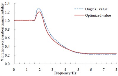
a) Vibration acceleration transmissibility in the vertical direction before and after optimization
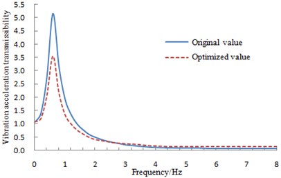
b) Vibration acceleration transmissibility in the horizontal direction before and after optimization
7. Conclusions
1) Based on the multi-directional vibration of vehicle seats and parallel mechanism, a new reduction suspension system with six degree of freedom was designed. This suspension system had less kinematic branches and compact structure and was easy to be controlled.
2) The stability indexes of the reduction vibration seat were proposed to obtain the task space of the moving platform. Based on task space and flexibility of suspension system, the structural parameters were finally determined to build the simulation model.
3) In order to verify the reliability of the simulation model, the experiment of vibration acceleration transmissibility was conducted and its result was then compared with that of the numerical computation. Their results were consistent with each other. It indicated that the simulation model was reliable and could be used for the subsequent analysis.
4) Influence factors of vibration acceleration transmissibility were researched based on the verified simulation model. In order to obtain a suspension system with a better reduction vibration performance, making the maximum vibration acceleration transmissibility in the vertical and horizontal direction be minimal was set as the optimization objective. And the above influence factors were taken as the design variables. Finally, the ride comfort of vehicles was improved. Meanwhile, this research can also provide some references for the similar engineering problems.
References
-
Choi S. B., Choi J. H., Lee Y. S., et al. Vibration control of an ER seat suspension for a commercial vehicle. Journal of Dynamic Systems, Measurement, and Control, Vol. 125, Issue 1, 2003, p. 60-68.
-
Xu Xiaomei, Zhu Sihong Theoretical analysis on the vibration characteristics of one kind of scissors linkage driver’s seat. China Mechanical Engineering, Vol. 17, Issue 4, 2006, p. 802-804.
-
Yao Weimin, Sun Dandan, Lin Yi Study of vertical vibration modal for decubitus body. Automotive Engineering, Vol. 6, 2002, p. 10-12.
-
Liu Huiying, Gai Yuxian, Zheng Chao Active control and system simulation of vertical vibration in a vehicle seat. China Mechanical Engineering, Vol. 6, Issue 12, 2006, p. 1227-1230.
-
Hauge G. S., Campbell M. E. Sensors and control of a spaced-based six-axis vibration isolation system. Journal of Sound and Vibration, Vol. 269, Issues 3-5, 2004, p. 913-931.
-
Chen Xiuxiang, Ma Lvzhong Study on mode and design of multi-vibration control device for vehicle equipment. Progress in Nature Science, Vol. 17, Issue 4, 2007, p. 551-555.
-
Wu Weiguang, Ma Lüzhong, Yang Qizhi, Chen Xiuxiang 3-D vibration isolation of vehicle seat based on parallel mechanism. Transactions of the Chinese Society for Agricultural Machinery, Vol. 6, 2011, p. 23-27.
-
Qizhi Y., Guoquan H., Long C., et al. Design of the damping seat based on parallel mechanisms. IEEE International Conference on Electric Information and Control Engineering, 2011, p. 2100-2103.
-
McManus S. J, Clair K. A. S., Boileau P. E., et al. Evaluation of vibration and shock attenuation performance of a suspension seat with a semi-active magnetorheological fluid damper. Journal of Sound and Vibration, Vol. 253, Issue 1, 2002, p. 313-327.
-
Choi S. B., Han Y. M. Vibration control of electrorheological seat suspension with human-body model using sliding mode control. Journal of Sound and Vibration, Vol. 303, Issue 1, 2007, p. 391-404.
-
Shim J. H., Kwon D. S., Cho H. S. Kinematic analysis and design of a six D.O.F. 3-PRPS in-parallel manipulator. Robotica, Vol. 17, 1999, p. 269-281.
-
Huayi C., Yung-Chih C. Dynamics analysis and learning control for 3-PRPS platform. International Journal of Computer Applications in Technology, Vol. 14, 2001, p. 204-214.
-
Xiaobin H., Gang G. Workspace analysis of 6-DOF 3-PRPS parallel robot. Machine Building and Automation, Vol. 41, Issue 1, 2013, p. 143-189.
-
Dan Zhang, Zhen Gao Hybrid head mechanism of the groundhog-like mine rescue robot. Robotics and Computer Integrated Manufacturing, Vol. 27, Issue 2, 2011, p. 460-470.
-
Luo You-gao, Zheng Xiang-zhou, Bin Hong-zan Workspace of translation 3-UPU parallel manipulator. Journal of Shanghai University, Vol. 9, Issue 1, 2005, p. 62-67.
-
Merlet J. P. Jacobian, manipulability, condition number, and accuracy of parallel robots. Journal of Mechanical Design, Vol. 128, Issue 1, 2006, p. 199-206.
-
Zhiqiang L. Ergonomics. China Machine Press, Beijing, 2006.
-
Guo L. Q., Wang D. F. Study on vibration transfer characteristic of commercial vehicle seats. Noise and Vibration Control, Vol. 29, Issue 4, 2009, p. 94-98.
-
Bouazara M., Richard M. J., Rakheja S. Safety and comfort analysis of a 3-D vehicle model with optimal non-linear active seat suspension. Journal of Terramechanics, Vol. 43, Issue 2, 2006, p. 97-118.
-
Ibrahim R. A. Recent advances in nonlinear passive vibration isolators. Journal of Sound and Vibration, Vol. 314, Issue 3, 2008, p. 371-452.
About this article

This project was supported by Research on Urea-SCR Catalyst Mechanisms of Deactivation, Fault Diagnosis and Fault-tolerant Control Method (E060407)
